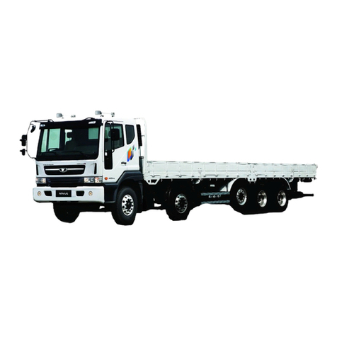
GMC 4000 Series User manual


SERVICE
MANUAL
SERIES
4000 THRU 6500
This manual includes procedures for
maintenance and adjustments, minor service
operations and replacement of components
GMC TRUCK & COACH DIVISION
GENERAL MOTORS CORPORATION
PONTIAC, MICHIGAN
General Motors Corporation, 1968 10M 9-68
GMC Truck & Coach Division rinted in U.S.A.
X-6933
SECTION INDEX
LUBRICATION a
CABS, HEATING AND
AIR CONDITIONING <■
FRAME cm
FRONT SUSPENSION cm
REAR SUSPENSION cm
BRAKES cm
GASOLINE ENGINES cm
TORO-FLOW
DIESEL ENGINES trm
ENGINE MOUNTINGS CM
ENGINE COOLING SYSTEM CM
ENGINE FUEL SYSTEM £Z|
AIR COMPRESSOR
AND GOVERNOR cm
ENGINE ELECTRICAL cm
TRANSMISSIONS
AND CLUTCHES cm
FUEL TANK & EXHAUST cm
STEERING SYSTEM cm
WHEELS & TIRES cm
SHEET METAL cm
CHASSIS ELECTRICAL
AND INSTRUMENTS cm
RADIATOR AND
SURGE TANK cm
SPECIAL TOOLS


INTRODUCTION
This manual contains on-the-vehicle maintenance, light repair information,
and unit replacement on all truck series listed on page v. Overhaul proce
dures for major units will be published in separate Unit Overhaul” manuals.
Important information on the arrangement and use of this manual will be
found on page iv. Operation of the vehicles from the standpoint of the driver is
contained in a separate Owner’s and Driver’s manual which is furnished with
every new GMC Truck.
Every effort has been made to include timely and adequate information on
the various units and systems used on GMC Trucks. The general maintenance
and light repair procedures in the various manual sections are the result of
extensive service experience. This information should serve not only as a ref
erence for the experienced mechanical force, but also as a comprehensive text
for training purposes.
In some cases, considerable space is devoted to describing the operation
of a unit or system. The use of this space is justified by the presumption
that in order for a mechanic to maintain a unit or system in a serviceable
condition, he must first understand how the unit or system should function.
All information contained in this manual is based on the latest product
information available at the time of publication approval. GMC Truck and
Coach Division reserves the right to make changes in design or add improve
ments at any time without incurring any obligation to install same on vehicles
previously purchased.
TRUCK MODEL DESIGNATION
(“L SERIES 4000)
(L) Tilt Cab (V) Hydraulic Brakes (A) Air Brakes
(ALL OTHER SERIES)
CHASSIS TYPE
SYMBOL
(E) Conv. Cab (92" BBC)
(P) Forward Control
(T) Tilt Cab
(S) Schoolbus Cowl
GVW RANGE NUMBER
See Load Capacity Chart”
in Owner’s and Driver’s
Manual. MODEL YEAR
SERIAL NUMBER
E M 40 V - D 020001
ENGINE TYPE
SYMBOL
(G) V6 Toro-Flow (Diesel)
(M) V6 Gasoline
(S) In-Line Gasoline
BODY AND BRAKE TYPE
P—Chassis Only (Hyd. Brakes)
V—Cab & Chassis (Hyd. Brakes)
A—Cab & Chassis (Air Brakes)
M—Cowl & Chassis (Hyd. Brakes)
Y—Cowl & Chassis (Air Brakes)
iii

GENERAL INFORMATION
IM ORTANT-READ THIS AGE
TRUCK MODELS COVERED
This manual contains on-the-vehicle” mainte
nance and light repair information on GMC Truck
Models listed on page v. Since many truck models
with various combinations of equipment are cov
ered in this manual, the reader must necessarily
refer to truck model applications and methods of
distinguishing design differences in each manual
section.
All standard equipment and the most commonly
used regular production options are included in
this manual. Many special equipment and acces
sory items are available on these GMC Trucks,
however, these items are too numerous to permit
their coverage in this manual.
MANUAL ARRANGEMENT
This manual is divided into major sections in the
sequence shown on the margin of the title page.
A black tab bearing the major section number is
placed on the first page of each major section which
indexes with the tab on the title page. Many of the
major sections are divided into sub-sections, each
sub-section containing important and specific in
formation on related units or components. A section
index is also included on the first page of each
major section, when the major section is divided
into sub-sections.
PAGE AND ILLUSTRATION NUMBERS
The manual pages are numbered consecutively
throughout the manual. Illustrations are numbered
consecutively within each section, or within each
sub-section when the major section is so divided.
SPECIFICATIONS
Service data, fits, and tolerances are listed at
end of each section or sub-section under the head
ing Specifications.” In some cases reference must
also be made to these Specifications.” for model
application and methods of distinguishing the
various design and construction differences.
Manufacturers model or part numbers are used
in many instances in the Specifications” tabula
tions. These numbers are provided primarily for
unit identification or truck model application refer
ence, and should be referred to when ordering
parts. All detail service part numbers must be
obtained from the applicable Parts Book.
SPECIAL TOOLS
Special tools and equipment are mentioned, and
in many instances illustrated, throughout the text.
These tools are specially designed to accomplish
certain operations efficiently and readily. Such
tools are mentioned in the text by tool vendor’s
numbers. These tools are not offered for sale by
GMC Truck and Coach Division. Information re
garding availability of these tools can be obtained
from your Zone Office or directly from the Tech
nical Publication Department at the Factory.
SERVICE BULLETINS
Service bulletins are issued, when required, sup
plementing or in some cases superseding infor
mation in this manual. Information in these bul
letins should be noted in the text of the applicable
manual section and the bulletin filed for ready
reference.
OPERATION
Operating instructions from the standpoint of
the driver are included in a booklet entitled Own
er’s and Driver’s Manual” which is placed in the
cab of every new GMC Truck.
ALPHABETICAL INDEX
Important subjects, with manual page number
references, are alphabetically listed in the index
in the back of this manual.
iv

MODEL DATA
TRUCK
SERIES
GMC
ENGINE CLUTCH FRONT AXLE REAR AXLE TRANSMISSION
STD. OPT STD. OPT. STD. OPT. STD. OPT. STD. OPT.
LA, LV-4000 305C 351C 12 13 F070 —H150 G161,16121,
T150, G361,
16221
435GL 435GD,
540GD, 540GL
DLA, DLV-4000 DH478 -12 13 F070 —H150 G161,16121,
T150, G361,
16221
435GL 435GD,
540GD, 540GL
EM-4500 305E -11 12 F055 -H110 H135, H150,
T150 435GL «5GD
ES-4500 250 292 11 12 F055 -H110 H135, H150,
T150 435GL 435GD
PS-4500 250 292 11 12 F050 -H110 H135 SM465 -
EG-5500V DH478 -12 13 F055 F07C H150 G161,16121,
T150, G361,
16221
435GL 435GD, 540GD,
540GL
EG-5500A DH478 -12 13 F070 -G161 16121, G361,
16221 435GL 435GD, 540GD,
540GL
EM-5500 305C 351C 12 13 F055 F070 H150 G161, 16121,
T150, G361,
16221
435GL 435GD, 540GD,
540GL
EM-5500 A & Y 305C 351C 12 13 F070 -G161 16121, G361,
16221 435GL 435GD, 540GD,
540GL
ES-5500 V & M 292 -12 -F055 F070 H150 G161,16121,
T150, G361,
16221
435GL 435GD,
540GD, 540GL
SG-5500M DH478 12 13 F055 F070 H150 G161,16121,
T150, G361,
16221
435GL 435GD, 540GD,
540GL
SG-5500Y DH478 -12 13 F070 -G161 16121, G361,
16221 435GL 435GD, 540GD,
540GL
SM-5500M 305C 351C 12 13 F055 F070 H150 G161,16121,
T150, G361,
16221
435GL 435GD, 540GD,
540GL
SM-5500Y 305C 351C 12 13 F070 -G161 16121, G361,
16221 435GL 435GD, 540GD,
540GL
SS-5500 292 -12 —F055 F070 H150 G161,16121,
T150, G361,
16221
435GL 435GD,
540GD, 540GL
EG-6500 DH478 -12 13 F070 -16121 17121, 16221,
17221 435GL 435GD, 540GD,
540GL
EM-6500 305C 351C 12 13 F070 -16121 17121, 16221,
17221 435GL 435GD, 540GD,
540GL
SM-6500 M & Y 351M —13 —F070 —16121 17121, 16221,
17221 435GL 435GD, 540GD,
540GL
v

VEHICLE MODEL IDENTIFICATION
AND WEIGHT RATING PLATE
The vehicle identification and
weight rating plate is located on
the cab left door pillar of all
models except P” and cowl mod
els. Plate location on P” and cowl
models is determined by the body
manufacturer.
ENGINE SERIAL NUMBERS
The engine serial number on V” engines is stamped on top of the cylinder
block ahead of the right-bank cylinder head as shown below. Engine serial
numbers are not used on in-line engines; numbers appearing on crankcase boss
at rear of distributor are manufacturing location and building date codes.
SERVICE PARTS IDENTIFICATION
The Service Parts Identification” label is located on inside of glove compart
ment door of steel tilt and conventional cab models. Location of label on P”
and cowl models is determined by the body manufacturer. This label lists all
special equipment installed on the vehicle. This information is imprinted on
the label at the factory and represents only the special equipment on the
vehicle when it was shipped from the factory. Always refer to this information
when ordering parts.
vi

GMC SERVICE MANUAL Sec. 0
Page 1
SECTION O
INDEX
Subject Page No.
Lubrication Charts
Except Steel Tilt Cab Models
.....................
2
Steel Tilt Cab Models .................................... 4
Engine and Accessories
................................ 6
Capacities
Crankcase ......................................................... 7
Transm ission..................................................... 7
Rear A x le ............................................................ 7
Engine Oil - Symbol "E"
...................................
7
Engine Oil Recommendations
.....................
7
Viscosities ......................................................... 8
Checking Engine Oil L e v e l
............................
8
Engine Oil F ilte r
.............................................. 8
Air Cleaners
Oil Bath Type .............................................. 9
Paper Element T y p e
...................................
10
Brake Power and Axle C ylinder
..............
10
Air Compressor Air Strainer
.................. 11
Other Engine Oil Uses
...................................
11
Crankcase Ventilation (Gasoline)
..................
12
Crankcase Ventilation (D iesel)
.....................
12
Subject Page No.
Multi-Purpose Gear Lubricant Symbol "MP"
Viscosities ......................................................... 12
Rear A x le ............................................................ 12
Transm ission
..................................................... 13
Chassis Lubricant - Symbol " C "
.....................
13
Steering Gear Lubricant - Symbol "SG" . . . 14
High Temperature Grease - Symbol "S2" . . 14
Wheel B earings.................................................. 14
Other High Temperature U s e s
.....................
14
Petroleum Jelly - Symbol "S3" ...................... 14
Distributor ......................................................... 14
Battery Terminals ........................................... 14
Waterproof Grease - Symbol "S4"
..............
15
Hydraulic Brake Fluid - Symbol "S12" . . . 15
Clutch and Brake Master Cylinder
..............
15
Soft, Smooth Cup Grease - Symbol "S16" . . . 15
Special Grease - Symbol "S17"
.....................
15
Automatic Transmission Fluid - Symbol "S19" . 16
Power Steering S yste m
...................................
16
High Temperature Grease - Symbol "S28" . . 16
Stop master Brake U n it
...................................
16
GENERAL INFORMATION
Lubrication charts on following pages will lo
cate each lubrication point on the series shown
under each chart. Each point is numbered on the
charts, and each number is keyed to explanatory
text on same or opposite page.
Each item shown on charts requiring lubrica
tion is covered with a lubricant symbol. Explan
ations of symbols start on page following charts.
Explanations include type of lubricant recommend
ed, and detailed instructions regarding its applica
tion. The charts show recommended intervals when
various items should be lubricated. The intervals
are recommended for normal use; however, oper
ating conditions may require more frequent inter
vals. Recommended intervals should be followed
until operating experience indicates other periods.
No particular brand of lubricant is recom
mended as many reputable oil dealers can furnish
the right lubricants when advised of the correct
specifications or descriptions. The lubricant man
ufacturer must be responsible for the quality and
satisfactory performance of his product. His rep
utation is your best indication of quality.
LUBRICANT SYMBOLS
Symbol Explanation Page No.
"E" Engine Oil ........................................... 7
"MP" Multi-Purpose Gear Lubricant . . 12
"C" Chassis L ubricant
............................
13
"SG" Steering Gear Lubricant
..................
14
"S-2" High Temperature G rease
..............
14
"S-3" Petroleum Jelly
................................ 14
"S-4" Waterproof Grease ......................... 15
"S-12" Hydraulic Brake F lu id
.....................
15
"S-16" Soft, Smooth Cup Grease
..............
15
"S-17" Special G rease
...................................
15
"S-19" Automatic Transmission Fluid . . 16
"S-28" High Temperature Grease (Special) 16

Sec. 0
Page 2 GMC SERVICE MANUAL
LUBRICATION
Figure 1 — Lubrication Chart (Except Steel Tilt Cab Models)

GMC SERVICE MANUAL Sec. 0
Page 3
LUBRICATION
LUBRICATION DATA
(CHART ON OPPOSITE PAGE)
Item
No. Item
1 Spring Shackles and Brackets (1)
2 Spring Slip Pads (1)
.......................
3 Steering Knuckles
.......................
4 Steering Tie Rod Ends
.................
5 Steering Drag L in k
.......................
6 Power Steering Cylinder Ends (1)
7 Prop. Shaft U-Joints
.......................
8 Prop. Shaft Slip Joint
....................
10 Speedometer Adapter
....................
11 Brake Camshaft (2)
.......................
12 Brake Master Cylinder (3)
...........
13 Steering Gear Housing
..............
14 Battery Terminals..........................
15 Electric Shift Unit (2-Spd.) . . . .
16 Transm ission
..................................
17 Rear Axle ........................................
18 Front Wheel Bearings
.................
19 Rear Wheel B earings
....................
20 Brake Cam Roller Pins (2) ..........................
21 Brake and Axle Cyl. Air Cleaner (1) . . . .
22 Steering Column U-Joints ..........................
23 Steering Column Slip Joints .......................
Remarks Sym. Miles i
2 fittings each sh a ck le
.................
..
C 6,000
1 fitting each bracket
....................
...
C 6,000
Apply each e n d
...............................
...
C 6,000
2 fittings each side .......................
...
C 6,000
1 fitting each end ..........................
...
C 6,000
1 fitting each end ..........................
...
C 6,000
2 fittings
.........................................
....
C 6,000
1 fitting each jo in t..........................
..
GO 6,000
1 fitting each join t..........................
..
C 6,000
1 fittin g
.............................................
..
C 6,000
1 fitting ea. (apply sparingly) . . C 6,000
Fill - 1/2" below opening............
...
S12 6,000
To level of filler plug
.................
...
SG 6,000
Keep coated
.....................................
..
S3 6,000
To level of filler plug
.................
...
S7 12,000
To level of filler plug
.................
..
MP 6,000
Drain and refill .............................
...
MP 12,000
To level of filler plug
.................
...
MP 6,000
Drain and refill .............................
...
MP 24,000#
Hand pack or use lubricator . . . S2 20,000*
Hand pack or use lubricator
Series 4500 & 5500
H110, H135, T150, H150,
G161, G361 .............................
...
S16 20,000*
All O thers........................................
...
S2 20,000*
Apply
................................................
...
E 20,000
Clean and reinstall
.......................
...
- 6,000
1 fitting each joint
.......................
..
C 6,000
1 fitting ...........................................
..
C 6,000
* Or once a year, whichever occurs first.
# Or every 6 months, whichever occurs first.
t When "C" Chassis Lubricant is specified, lubricate every 6,000 miles or 60 days, whichever occurs first.
(1) Some Models.
(2) Air Brake only.
(3) Hydraulic Brakes only.

Sec. 0
Page 4 GMC SERVICE MANUAL
LUBRICATION
Figure — Lubrication Chart (Steel Tilt Cab Models)

GMC SERVICE MANUAL Sec. 0
Page 5
LUBRICATION
LUBRICATION DATA
(CHART ON OPPOSITE PAGE)
Item
No. Item Remarks Sym. Miles $
1Spring Shackles and Brackets
....................
2 fittings each shackle............ . . c 6,000
1 fitting each bracket ............ .. c 6,000
2Spring Slip Pads - Rear
..................................
Apply each end
.
......................... .. c 6,000
3 Steering Knuckles........................................... 2 fittings each s id e
.................
.. c 6,000
4 Steering Tie Rod E n d s
..................................
1 fitting each end
....................... .. c 6,000
5Steering Drag Links........................................ 1 fitting each end
....................
.. c 6,000
6Power Steering Cylinder Ends (1 )
..............
2 fittings
.....................................
.. c 6,000
7Cab Hinges......................................................... 1 fitting each s id e
....................
.. c 6,000
8Cab Hold-Down Latch
..................................
1 fitting
..................................... .. c 6,000
9Brake Camshafts (2)
............................
1 fitting e a c h ............................. . . c 6,000
10 Clutch and Brake Pedals
...............................
2 fittin gs
.......................... .. c 6,000
11 Air-Hydraulic Cylinder ( 3 ) .......................... To level of plug ..................... . . S6 12,000
12 Prop. Shaft U-Joints ..................................... 1 fitting each joint
.................
. . GO 6,000
13 Prop. Shaft Slip Joints
..................................
1 fitting each joint
.................
.. c6,000
14 Steering Column U -Joints............................. 1 fitting each joint
.................
. . GO 6,000
15 Steering Column Slip J o in t.......................... 1 fitting
..................................... .. c 6,000
16 Speedometer Adapter..................................... 1 fitting ..................................... .. c 6,000
17 Transmission Shift L evers.......................... 2 fittings
..................................
.. c 6,000
18 Transmission Shift Linkage (NP 540) . . . . 1 fitting
..................................... .. c 6,000
19 Steering Gear Housing
..................................
To level of filler plug ............ . . SG 6,000
20 Brake Master Cylinder (3 )............................. Fill - 1/2" below opening . . . . . S12 6,000
21 Battery T erm inals........................................... Keep coated ............................. . . S3 6,000
22 Electric Shift Unit (2-Spd.) .......................... To level of filler plug ............ . . S7 12,000
23 T ransm ission
...................................................
To level of filler plug
............
. . MP 6,000
Drain and refill
.......................
. . MP 12,000
24 Rear Axle ......................................................... To level of filler plug
............
. . MP 6,000
Drain and refill
.......................
. . MP 24,000#
25 Front Wheel Bearings
..................................... Hand pack or use lubricator .. . S2 20,000*
26 Hand pack or use lubricator
H110, H135, T150, H150,
G161, G361 ....................... . . S16 20,000*
All Others ............................. 20,000*
27 Brake Cam Roller Pins (2) .......................... Apply ........................................... . . E 20,000
28 Brake Power and Axle Cylinder
Air Cleaner (1) ........................................... Clean and reinstall
.................
6,000
* Or once a year, whichever occurs first.
# Or every 6 months, whichever occurs first.
+ When "C" Chassis Lubricant is specified, lubricate every 6,000 miles or 60 days, whichever occurs first.
(1) Some Models.
(2) Air Brakes only.
(3) Air-Hydraulic Brakes only.

Sec. 0
Page 6 GMC SERVICE MANUAL
LUBRICATION
Item
No. Item
1 Engine .............................................................
2 Engine Oil Filter
.......................................
3 Engine Air Cleaner ....................................
4 Crankcase Breather (1 )
................................
5 Air Compressor Air Strainer (1) . . . .
6 Governor Air Filter (2) .............................
7 Distributor (2)
..............................................
8 Generator ..................................................
9 Starter ......................................................
10 Power Steering Reservoir (1 )
..................
(1) Some Models.
(2) Gas Engine Only.
# Replace lubricator at 24,000 mile intervals.
Remarks Sym. Miles
Keep to "FULL" mark . . . . . . E Daily
See instructions
..................
. . . —
Clean and r e f i l l
..................
3,000
See instructions
..................
. . . --
Clean and insta ll
..................
. . . 6,000
Clean and in sta ll
..................
. . . 6,000
1/2 turn of cam lubricator . . . . 12,000#
Breaker pivot - 1 drop . . . . . . E 6,000
Rotor felt - 4 drops . . . . . . . E 6,000
No lubrication required . . - -
See instructions
..................
. . . E —
To "OIL LEVEL" mark . . . . . S19 6,000
Figure 3— Engine Lubrication Charts

GMC SERVICE MANUAL Sec. 0
Page 7
LUBRICATION
CAPACITIES
TRANSMISSION CAPACITIES
CRANKCASE CAPACITIES
ENGINE LESS FILTER WITH FILTER
MODEL QTS.* QTS.*
U.S.. IMP. U.S. IMP.
250
....................
. . 4 3-1/4 5 4-1/4
292* - 305E . . . 5 4-1/4 .6 5
305C* - 351C*. . 86-3/4 9 7-1/2
351M .................. 86-3/4 10 8-1/2
DH478**............ . . 11 9-1/4 13 10%
* Add one quart when 2-■qt. filter is used.
** Add one quart when oil cooler is drained.
Crankcase capacities are for normal refill.
Add oil as indicated when oil filter is drained and
element changed. Capacities given may be approx
imate - keep level as close as possible to "FULL"
mark without over-filling. Do not operate with
level below "ADD" mark.
PINTS
U.S. IMPERIAL
SM465 ............................. 8
..............
6-3/4
NP435 ............................. 7 ............... 5-3/4
NP540 ............................. 10
..............
8-1/4
REAR AXLE CAPACITIES
PINTS
BEVEL U.S. IMPERIAL
H110 ............................. 14
...............
11-3/4
H135 ............................. 20
...............
16-3/4
H150 ............................. 20
...............
16-3/4
G161
............................. 21
...............
17-1/2
E16121
.........................
24
...............
20
E17121
.
........................
29
...............
24-1/4
TWO-SPEED
T150 .............................
....
18
...............
...
15
G361 .............................
....
21
...............
...
17-1/2
E16221
.........................
....
24
...............
...
20
E17221
.........................
....
29
...............
...
24-1/4
ENGINE OIL
(SYMBOL “E ON CHARTS)
RECOMMENDATIONS
The oil industry markets various types of en
gine oil under certain service designations and
specification numbers.
The selection of a reliable supplier, with close
attention to his oil and filter element change rec
ommendations can provide satisfactory lubrication
and longer life for engine.
DIESEL ENGINE
Use Only High Quality Oils Which Are:
(1) MIL-L-2104B engine oils (see Note).
- or -
(2) Oils which pass the vehicle manufacturers
tests (including General Motors Standard
GM 6042M).
NOTE: Supplement 1 engine oils (based upon
now obsoleted MIL-L-2104A) have been superseded
by MIL-L-2104B engine oils, so these Supplement
1 oils are therefore becoming unavailable. How
ever, where a history of satisfactory performance
with Supplement 1 oils has been established, they
can still be used.
The use of proper engine oils and oil change
intervals are your best assurance of continued re
liability and performance of engine.
IMPORTANT: Non-detergent and other lower
quality engine oils are specifically not recommend
ed in diesel engines.
GASOLINE ENGINE
Use Only High Quality Oils Which Are:
(1) Intended for Service Designations "MS"
and "DM" (see Note).
- or -
(2) Products passing vehicle manufacturers
tests (including General Motors Standard
GM 6042M).
NOTE: Supplement 1 engine oils based upon
now obsoleted MIL-L-2104A) have been superseded
by MIL-L-2104B engine oils. However, Supplement
1 engine oils (MS - DM) with a history of satis
factory performance are available and may be used.
The use of proper engine oils and oil change
intervals are your best assurance of continued re
liability and performance of engine.

Sec. 0
Page 8 GMC SERVICE MANUAL
LUBRICATION
IMPORTANT: Non-detergent and other lower
quality engine oils are specifically not recom
mended.
BREAK-IN OILS AND ADDITIVES
The use of proprietary blends of supplement
ary additives or concentrates such as engine oil
supplements, break-in oils, tune-up compounds,
friction reducing compounds, etc., is not recom
mended in lubricating oils of the diesel engines
in GMC Truck and Coach vehicles. For gasoline
engines, if greater stability or detergency is de
sired to reduce varnish and sludge formations, and
minimize wear, a thoroughly tested and approved
concentrate is available from GMC Dealers.
VISCOSITIES
Atmospheric temperatures and severity of
service determine the viscosity grade of engine oil
to use. Viscosity numbers constitute a classifica
tion of lubricants in terms of viscosity or fluidity,
but with no reference to any other characteristics
or properties.
GASOLINE ENGINES
As a guide to the selection of the proper grade
or viscosity of oil to be used in gasoline engines at
various atmospheric temperatures, refer to "Vis
cosity Chart" (fig. 4).
VISCOSITY CHART
For cold weather, select viscosity based on lowest anticipated temperature.
For hot weather, select viscosity based on highest temperature expected during
the day. T_4 5 5 ,
Figure 4— Gasoline Engine Oil Viscosity Chart
DIESEL ENGINES
S.A.E. 30 engine oil is recommended for year
around use. Where cold weather starting isaprob-
lem, it is suggested that other starting aids, oil
and coolant system heaters, as well as proper fuel
selection will be helpful. For further assistance,
consult your authorized GMC Dealer.
Lower S.A.E. engine oil grades (S.A.E. 20,
S.A.E. 10, etc.), and the multi-viscosity oils(10W-
30, etc.), are not recommended, except as a last
resort. If used, they should be replaced withS.A.E.
30 as soon as possible.
MULTI-VISCOSITY TYPE ENGINE OILS
Multi-Viscosity lubricating oils, as a group,
are not normally recommended. However, some
may be effectively used to facilitate starting when
prolonged exposure of the engine to temperatures
below freezing is unavoidable. Consult your sup
plier regarding the performance characteristics of
this type of oil and obtain his assurance of ade
quate lubrication before subjecting the engine to
heavy-duty service.
OIL CHANGE INTERVALS
It is recommended that new engines should
have the first oil change at 3,000 miles.
The drain interval may then be increased or
decreased, depending upon experience with specific
oils or the recommendations and used oil analyses
as furnished by the supplier. Such a procedure
would be helpful in establishing the most practical
oil change period for the particular service.
CHECKING ENGINE OIL LEVEL
Daily, or oftener if necessary, check oil level.
Make the check perferably after a day’s run and
after engine has been stopped for a few minutes.
Remove dipstick, wipe clean with cloth, reinsert
and remove again. The upper mark on dipstick is
"FULL," the lower "ADD." Keep level as close as
possible to "FULL" mark without overfilling. Do
not operate with level below "ADD" mark.
On gasoline and diesel engines dipstick is on
right side and engine can be filled at right filler on
valve rocker cover after removing filler cap (fig.
5). On steel cab models, accessibility is through
door behind passenger seat. On other models, dip
stick and oil filler are accessible when hood is
raised.
ENGINE OIL FILTER
Oil filter element changing periods are closely
related to crankcase oil changing periods, the qual
ity of oil used, or the severity of the trucks service.

GMC SERVICE MANUAL Sec. 0
Page 9
It is recommended that element be changed initially
at first oil change and thereafter at intervals in
dicated under "Engine Oil Recommendations."
Location of oil filter is at left rear on gasoline
and diesel models (fig. 6).
ELEMENT TYPE
1. Remove plug in filter shell to drain oil
from filter.
2. Back out center stud and withdraw shell,
element, and stud as an assembly.
3. Remove and discard element.
4. Clean filter shell of old oil or other
deposits.
5. Replace old filter shell gasket in groove of
filter base.
6. Position new filter element in shell, THEN
FILL SHELL WITH OIL.
7. Install shell and element assembly on filter
base, then tighten center stud being careful that
gaskets are not damaged. Torque to 40 to 50 foot
pounds.
8. Start engine and operate at idle speed for
a few minutes until oil pressure builds up to
normal.
9. Check filter for leaks, then check dipstick
level. Add oil to bring level up to (not above)
dipstick mark.
DISPOSABLE TYPE
1. Turn filter from mounting on engine, then
discard assembly.
2. Thoroughly clean mounting at gasket area.
3. Apply lubricant to filter gasket. Fill ele
ment shell with engine oil, then thread filter onto
mounting stud until gasket touches mounting, then
tighten filter two-thirds more, which should pro
vide the required torque of 10 to 15 foot-pounds.
4. Whenever new element is installed, the
engine should be run and the filter inspected for
signs of an oil leak. The engine should then be
stopped, and the oil level brought up to the "FULL"
mark on the oil level dipstick.
AIR CLEANERS
Air cleaners must be serviced a minimum of
every 3,000 miles, or whenever dirt becomes vis
ible in the element or oil. Under extreme dirty
conditions inspection may be required daily. Air
cleaners on vehicles operating in dust storm areas
should be cleaned immediately after such storms
occur.
Several types of air cleaners are used. De
pending upon the vehicle model, each type cleaner
is serviced and mounted in a different manner.
LUBRICATION
Figu e 5— Oil Fille and Dipstick IGasoline and To o-Flow)
WARNING— DIESEL ENGINE
USE EXTREME CAUTION TO BE
SURE THAT ALL VOLATILE CLEANING
FLUID (GASOLINE, KEROSENE, ETC.
IS REMOVED FROM AIR CLEANER AT
TIME OF CLEANING, UNCONTROLLED
FUEL ENTERING THE COMBUSTION
CHAMBER IN THIS MANNER CAN CAUSE
THE ENGINE TO "RUN-AWAY" AND
POSSIBLY DESTROY ITSELF ANDCAUSE
INJURY TO PERSONNEL.
OIL BATH TYPE (Figs. 7 and 9)
Oil bath type air cleaners are mounted direct
ly to the engine or on cab dash. Loosen thumb
screw on top, then separate cover and element
from reservoir.
TH RO W -A W A Y TYPE REPLACEABLE ELEMENT TYPE
T-3456
Figure 6— Engine Oil Filters

Sec. 0
Page 10 GMC SERVICE MANUAL
LUBRICATION
Figu e 7— Ai Cleane — Oil Bath ITypical)
Remove reservoir and drain oil. Immerse all
parts in cleaning solution until all dirt or other
foreign matter is removed. Do NOT use com
pressed air on element. Be sure all volatile fluid
is removed.
Fill reservoir to "OIL LEVEL" mark, using
same grade oil used in engine. Assemble and re
install reservoir and element in reverse order of
removal and disassembly.
PAPER ELEMENT TYPE
- DRY OR PAPER WETTED (Fig. 8)
Remove wing nut from stud at top of air clean
er, then lift cover and element from base.
To determine if an air filter element requires
cleaning or replacement, use air filter viewer,
A.C. Part Number 6484631, which has a special
lens for this purpose. A dirt-clogged element pre
vents the light from being visible from outside.
The paper-wetted type has been impregnated with
oil and cannot be cleaned. When dirt clogged, or
when light as described above is not visible, the
element must be replaced.
Some dry elements are washable; refer to
decal for instructions.
Clean element by shaking out accumulated
dirt, or clean by washing with water and detergent
only. Rinse until water runs clean. Shake off ex
cess water and dry. DO NOT OIL ELEMENT.
NOTE: Install a new element after five (5)
cleaning. Some elements also have a band of syn
thetic material (polyurethane) which is cleanable
in kerosene or mineral spirits.
Install assembly in reverse order of "Re
moval" and ’’Disassembly" procedure.
BRAKE POWER AND AXLE
CYLINDER AIR CLEANER
Several types of cleaners are used for this
purpose. Two types - one disposable and the other
BASE T-5773
Figu e 8— Ai Cleane — Pape Element
with Polyu ethane (Typical) Figure 9— Air Cleaner (Toro-Flow Engine)

G M C SERVICE MANUAL
_________________________
page 11
LUBRICATION
Figu e 10— Ai Comp esso Ai St aine
cleanable - is located on inside of cab at left rear
corner. Another type is made of polyurethane and
is installed in brake booster cylinder.
Cleanable Type
Lift element assembly from tube. Wash ele
ment thoroughly in cleaning solvent until all ac
cumulated dirt is removed. Dry thoroughly, then
reinstall. Do not oil element.
Disposable Type
Remove retaining bolt, then lift assembly
from tube. When inspection indicates the assembly
is dirty it should be discarded and a new assembly
installed.
Polyurethane Type
This cleaning element is removable for in
spection and cleaning as instructed in BRAKES
(SEC. 5). Element is cleaned by immersing and
squeezing in kerosene or mineral spirits.
IMPORTANT
Regardless of where an air cleaner
is used, it is extremely important that
element be cleaned as directed to assure
extended life of applicable unit.
DISTRIBUTOR
Breaker Pivot. Remove distributor cap and
apply one drop of S.A.E. 10 engine oil to breaker
arm pivot. Do not apply excessive lubricant.
Rotor Felt. A felt is used under rotor of some
distributors. Apply 3 or 4 drops of S.A.E. 20 engine
oil.
AIR COMPRESSOR AIR STRAINER
(Refer to Fig. 10)
The air compressor air strainer should be
replaced regularly. Figu e 12— C ankcase Ventilation System (Diesel)
Figu e 1 1 — C ankcase B eathe (V6 Gasoline Engine)
Paper element type air compressor cleaner
is used on all models and should be replaced when
element shows visible evidence of damage or a
dirt clogged condition or is oil saturated.
OTHER ENGINE OIL USES
FILTER
SEPARATOR

Sec. 0
Page 12 GMC SERVICE MANUAL
LUBRICATION
STARTER
Some starters are equipped with oiler or plug
at drive end, plug at commutator end, and plug at
middle bearing. At the time of installation, apply
S.A.E. 20 at plugs or oilers.
LINKAGE
Engine oil is used also to lubricate clevis
pins, linkage, clevises, etc. Application should be
made by brush or spray.
AXLE SHIFT UNIT
Remove plug in cover and fill to level of open
ing with S.A.E. 10 engine oil.
CRANKCASE VENTILATION
GASOLINE ENGINES
The closed positive crankcase ventilation sys
tem makes an important contribution to the reduc
tion of air pollution by recycling fuel fumes, which
enter the crankcase, back to the combustion cham
ber to be burned, and achieves nearly one-hundred
percent elimination of crankcase emissions - one-
third of total hydrocarbon emissions from vehicle.
Ventilation valves on "V" engines are threaded
into cylinder heads, while valve on In-line engines
is installed in rocker arm cover. At first engine
oil change ventilation valve(s) should be checked
for proper operation as described in GASOLINE
ENGINES (SEC. 6A) under "Crankcase Ventilation
System." Every 12 months or 12,000 miles, which
ever occurs first, the valve(s) MUST be replaced.
Also, all hoses and fittings (including flame arrest
er on In-line engine) should be inspected, cleaned,
and replaced if necessary.
On V6 engines, a crankcase breather (fig. 11) is
installed at valve rocker arm cover and should be
removed and cleaned at each oil change interval.
DIESEL ENGINE
Oil separator, breather tube and filter assem
bly (fig. 12) are installed at opening in rear of
crankcase on diesel engines. A mesh filter element
is contained in a retainer which should be removed
every 30,000 miles and cleaned of accumulations
by immersing repeatedly in fuel oil or cleaning
solvent, until all deposits are removed.
MULTI-PURPOSE GEAR LUBRICANT
(SYMBOL “MP ON CHARTS)
Multi-Purpose Gear Lubricant, meeting U.S.
Army Ord. Specification MIL-L-2105B and indi
cated by the symbol "MP” on charts, must satis
factorily lubricate heavy duty truck hypoid or bevel
axles, and transmissions, under maximum torque
and speed conditions. It must provide necessary
and suitable load-carrying characteristics to pre
vent scoring and wear, good stability in storage
and service, and give good resistance to corrosion.
Suppliers should assure these characteristics, and
be responsible for the quality and satisfactory per
formance of their products.
VISCOSITIES
ROCKWELL AXLES
In Rockwell axles, S.A.E. 140 should be used
the year around except in cases of extremely low
temperatures. If trucks are parked in tempera-
atures below +20°F., or operated in temperatures
consistently below 0°F., it is advisable to use S.A.E.
90.
OTHER UNITS
S.A.E. 90 may be used the year around. If
truck is operated in temperatures consistently
below 0°F., use S.A.E. 80. If the truck is operated
in consistently high temperatures (over 100°F.),
S.A.E. 140 may be used.
REAR AXLE
CHECKING LEVEL
Remove filler plug and if necessary, add suf
ficient lubricant to bring the level up to filler plug
level. Install and tighten plug. On the forward rear
axle with torque divider, be sure that vehicle has
stood for at least 5 minutes before checking level;
then check level AT REAR FILLER HOLE.
DRAINING AND FILLING
When axle is new, or after overhaul, it is
recommended that lubricant be drained after the
first 3,000 miles of operation, and thereafter at
recommended intervals. Draining at an early mile
age removes fine particles of metal or other for
eign material.
At specified intervals remove plug at bottom
of axle housing, also at bottom of torque divider
or inter-axle differential housing on tandem bevel
axles. Drain when unit is hot, preferably immed
iately after operation. Reinstall drain plugs.
Fill axle to level of filler plug opening. On
tandem axles with torque divider, add specified
quantity through filler plug on side of case or add
two pints of lubricant at top of inter-axle differ
ential housing.
SPECIAL AXLE LUBRICATION
Special lubrication is required on all axles as

GMC SERVICE MANUAL Sec. 0
Page 13
LUBRICATION
follows: (1) when axle has not been operated for a
long period (2) has been out of normal position or
(3) after overhaul.
Add one pint of lubricant through plug opening
in top of pinion cage or differential carrier. Re
check lubricant.level at filler plug.
TRANSMISSION
CHECKING LEVEL (Fig. 13)
At specified intervals remove filler plug at
side of case and, if necessary, add sufficient rec
ommended lubricant to bring lubricant level up to
level of opening. Install and tighten filler plug.
DRAINING AND FILLING (Fig. 13)
When transmission is new, or after overhaul,
it is recommended that lubricant be drained after
the first 3,000 miles of operation, and thereafter
at recommended intervals. Draining at early mile
age removes fine metal or other foreign material.
At specified intervals, preferably immediately
after operation while unit is hot, remove plug to
drain lubricant. Clean drain plug, then reinstall
Figu e 13— T ansmission D ain and Level Plug (Typical)
and tighten securely. Refill to level of filler plug
opening as directed above. Use S.A.E. 90 the year
around in transmissions.
CHASSIS LUBRICANT
(SYMBOL “C ON CHARTS)
The lubricant indicated by symbol "C" on charts
should be a high grade pressure gun lubricant.
Good quality lithium soap multi-purpose grease
is recommended, especially for extreme operating
conditions - water, heat, etc.
UNIVERSAL JOINTS
At specified intervals, use pressure gun to
apply lubricant through fitting in universal joint
trunnion. Apply until lubricant is forced out around
all four trunnion seals (fig. 14). Good quality Lith
ium soap multi-purpose grease is recommended.
APPLYING CHASSIS LUBRICANT
All lubrication fittings must be clean before
applying lubricant. Always be sure equipment used
in applying lubricant is clean. Every precaution
should be taken to prevent entry of dirt, grit, lint,
or other foreign matter into lubricant containers.
Fittings that have become broken or damaged
should be replaced with new part, and can be re
moved with a wrench or suitable extracting tool.
COLD WEATHER PREPARATION
When hard steering is encountered as a result
of cold weather, the steering system should be lu
bricated as follows:
Use steering gear lubricant (Symbol "SG") or
Multi-Purpose Grease (N.L.G.I. #0) to lubricate
all steering linkage such as steering knuckles, tie
rod ends, and (if used) power steering booster cyl
inder ends. In warmer weather, relubricatelinkage
with chassis grease previously recommended.
U-JO IN T FITTING
T-2451
Figure 14— Universal and Slip Joint Lubrication
Filler Plug
Drain Plug TPM-8839
This manual suits for next models
1
Table of contents
Other GMC Truck manuals

GMC
GMC HUMMER EV 2023 User manual

GMC
GMC 2005 T-Series User manual

GMC
GMC 1986 P-Truck User manual

GMC
GMC T Series 1994 Operating instructions

GMC
GMC PD-4103 User manual

GMC
GMC 1990 Light Truck Operating instructions

GMC
GMC C Series 1993 Operating instructions

GMC
GMC 1982 Light Duty Truck User manual

GMC
GMC G User manual

GMC
GMC 2010 T-Series User manual
Popular Truck manuals by other brands

Wittke
Wittke StarLight Maintenance manual

Komatsu
Komatsu HD1500-5 Operation & maintenance manual

Capacity
Capacity TJ5000 OFF ROAD Operator's handbook

Chevrolet
Chevrolet Silverado 4500HD 2022 Getting to know your

freightliner
freightliner BUSINESS CLASS M2 Driver manual

Still
Still ECH 12 Original instructions