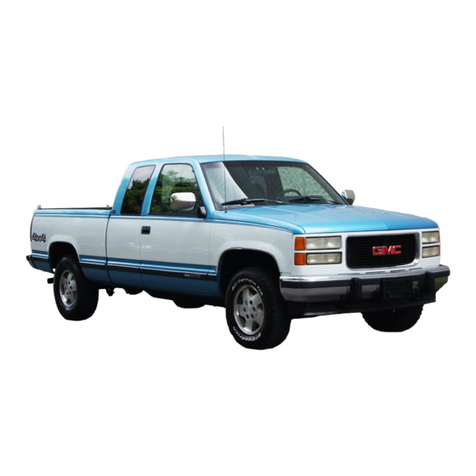
GMC 1990 Light Truck Operating instructions

G M C
T R U C K
1990
LIGHT TRUCK


FOREWORD
This manual includes procedures involved in disassembly and assembly of components
listed in the "Table of Contents.”
This manual should be kept in a handy place for ready reference. f properly used, it will
meet the needs of technicians and vehicle owners.
CAUTION:
These vehicles contain some parts dimensioned in the metric system as well as in the
customary system. Some fasteners are metric and are very close in dimension to familiar
customary fasteners in the inch system. t is important to note that, during any vehicle
maintenance procedures, replacement fasteners must have the same measurements and
strength as those removed, whether metric or customary. (Numbers on the heads of metric
bolts and on surfaces of metric nuts indicate their strength. Customary bolts use radial
lines for this purpose, while most customary nuts do not have strength markings.) Mis
matched or incorrect fasteners can result in vehicle damage or malfunction, or possibly
personal injury. Therefore, fasteners removed from the vehicle should be saved for re-use
in the same location whenever possible. Where the fasteners are not satisfactory for re
use, care should be taken to select a replacement that matches the original. For informa
tion and assistance, see your authorized dealer.
GMC TRUCK OPERATION
TRUCK & BUS GROUP
General Motors Cor oration
Pontiac, Michigan
No part of this publication may be reproduced, stored in any retrieval system or transmit
ted, in any form or by any means, including but not limited to electronic, mechanical, photo
copying, recording or otherwide, without the prior written permission of the GMC Truck
Division of General Motors dorp. This includes all text, illustrations, tables and charts.

CAUTION
To reduce the chance of ersonal injury and/or ro erty damage, the following
instructions must be carefully observed.
Pro er service and re air are im ortant to the safety of the service technician
and the safe, reliable o eration of all motor vehicles. If art re lacement is
necessary, the art must be re laced with one of the same art number or with
an equivalent art. Do not use a re lacement art of lesser quality.
The service rocedures recommended and described in this service manual
are effective methods of erforming service and re air. Some of these roce
dures require the use of tools s ecially designed for the ur ose.
Accordingly, anyone who intends to use a re lacement art, service roce
dure or tool, which is not recommended by the vehicle manufacturer, must first
determine that neither his safety nor the safe o eration of the vehicle will be
jeo ardized by the re lacement art, service rocedure or tool selected.
It is im ortant to note that this manual contains various Cautions and
Notices that must be carefully observed in order to reduce the risk of ersonal
injury during service or re air, or the ossibility that im ro er service or re air
may damage the vehicle or render it unsafe. It is also im ortant to understand
that these ‘Cautions’ and ‘Notices’ are not exhaustive, because it is im ossible
to warn of all the ossible hazardous consequences that might result from
failure to follow these instructions.

TABLE OF CONTENTS
1990
UNIT REPAIR
MANUAL
COVERING
LIGHT DUTY
TRUCKS
The Table of Contents on this page indicates the
sections covered in this manual. At the beginning of
each individual section is a Table of Contents which
gives the page number on which each major subject
begins.
When reference is made in this manual to a brand
name, number, or specific tool, an equivalent product
may be used in place of the recommended item.
All information, illustrations, and specifications con
tained in this Manual are based on the latest product
information available at the time of publication approv
al. The right is reserved to make changes at any time
without notice.
X-9037
©1989 General Motors Corporation February, 1989
Printed in USA All rights reserved.
SEC. SECTION NAME
OA GENERAL INFORMATION
1AIR CONDITIONING
1B1 A6 Air Conditioning Compressor
1B2 V5 Air Conditioning Compressor
1B3 R-4 Air Conditioning Compressor
1B4 HR-6 Air Conditioning Compressor
1B5 SD-709 Air Conditioning Compressor
3 STEERING
3B2 Manual Steering Gear
3B3 Power Steering
4AXLES
4B Rear Axle
4B1 7 1/2- nch Ring Gear
4B2 8 1/2- nch Ring Gear
4B3 9 1/2- nch Ring Gear
4B4 10 1/2- nch Ring Gear
4B5 Dana Rear Axles
4B6 12- nch Ring Gear (Rockwell)
4B7 Locking Differentials
4C Front Axle
4C1 8 1/2- nch Ring Gear
4C2 9 3/4- nch Ring Gear (Dana)
4C3 T Truck Front Axle
4C4 K Truck Front Axle 8 1/4 and 9 1/4- nch
Ring Gear
4C5 L Van Front Axle
5 BRAKES
6 ENGINE
6A General Engine
6A1 2.5 Liter L4
6A2 2.8 Liter V6
6A3 4.3 Liter V6
6A4 4.8 Liter L6
6A5 V8 Engine
6A7 6.2 Liter Diesel
6C Carburetor and TB Unit
6C1 Model 1MEF Carburetor
6C2 Model M4MEF Carburetor
6C3 TB Unit Model 220
6C4 TB Unit Model 700
6D Engine Electrical
6D1 S Series Generators
6D2 CS-144 Generator
6D3 SD Starting Motors
6D4 PG-200 (PMGR) Starting Motor
6D5 Distributors
7TRANSMISSION
7A Automatic Transmission
4L60 Hydra-matic 4L60 (700-R4)
3L80 Hydra-matic 3L80/3L80-HD (400/475)
3L30 Hydra-matic 3L30 (180C)
7B Manual Transmission
7B1 Hydra-Matic 5LM60 (HM-290)
7B2 HM-117
7B3 New Process Transmission
7B4 Borg Warner Transmissions
7D Transfer Case
7D1 New Process 205 Transfer Case
7D2 New Process 241 Transfer Case
7D3 New Process 231 Transfer Case
7D4 Borg Warner 1370 Transfer Case
7D5 Borg Warner 4472 Transfer Case

No one
knowsyour
GM truck
better.
No one.
Mr. Goodwrench wants you to have the right parts for
your truck—whether you see him for service or whether
you do the work yourself.
That's why Mr. Goodwrench wants to have a good
stock of genuine GM Parts available. Everything from
exclusive GM Goodwrench replacement engines and
transmissions to GM Goodwrench Motor Oil that meets
or exceeds all specifications for General Motors cars
or light trucks. And Mr. Goodwrench has a complete
line of GM chemicals for fine care of your GM vehicle.
Plus accessories to add convenience—
or just a little extra style.
So keep that great GM feeling with genuine GM parts
at participating independent Mr. Goodwrench dealers
selling Chevrolets, Pontiacs, Oldsmobiles, Buicks,
Cadillacs, GMC and Chevy Trucks.
in
.........
.
IPIs&igimEl
NMIAL MOTOI8 OOiPOflATtON
F5085
IV

GENERAL INFORMATION OA-1
SECTION OA
GENERAL INFORMATION
CONTENTS
SUBJECT PAGE
Service Parts Identification Label .........................................................................................................................OA- 1
Vehicle Identification Number .................................................................................................................................OA- 1
Certification Label ......................................................................................................................................................OA- 1
Engine Identification Number ..................................................................................................................................OA- 2
"Transmission Identification Number .....................................................................................................................OA- 3
Model Reference ......................................................................................................................................................... OA- 3
Metric Fasteners ......................................................................................................................................................... OA- 3
Fastener Strength Identification ............................................................................................................................ OA- 5
Six Lobed Socket Head Fasteners ........................................................................................................................OA- 5
Prevailing Torque Fasteners ...................................................................................................................................OA- 5
Conversion Table .......................................................................................................................................................OA-13
Decimal and Metric Equivalents ............................................................................................................................ OA-14
SERVICE PARTS
IDENTIFICATION LABEL
The Truck Service Parts dentification Label is pro
vided on all models (figure 1). t is located on the
inside of the glove box door (or on an inner body panel
for Forward Control models). The Label lists the V N
(Vehicle dentification Number), wheelbase, paint infor
mation and all Production options or Special Equip
ment on the vehicle when it was shipped from the
factory. ALWAYS REFER TO TH S NFORMAT ON
WHEN ORDER NG PARTS.
VEHICLE IDENTIFICATION
NUMBER
The V N is the legal identifier of the vehicle. On all
models except Forward Control, it is located on a plate
which is attached to the left top of the instrument panel
and can be seen through the windshield from the out
side of the vehicle (figure 2). On Forward Control mod
els, the plate is on the dash and toe panel. To find out
the manufacturer, model and chassis type, engine
type, GVW range, model year, plant code, and sequen
tial number, refer to figure 3.
CERTIFICATION LABEL
The Certification Label shows the GVWR, and the
front and rear GAWRs, and the Payload Rating for
your vehicle (figure 4).
Gross Vehicle Weight (GVW) is the weight of the
orginally equipped vehicle and all items added to it
after it has left the factory. This would include bodies,
winches, booms, etc.; the driver and all occupants; and
the load the vehicle is carrying. The GVW must not
exceed the GVWR. Also, the front and rear gross axle
weights must not exceed the front and rear GAWRs.
The Payload Rating shown on the label is the maxi
mum allowable cargo load (including the weight of the
1. V N 6 5
2. Wheel Base 5. RPO/SEO Codes
3. Model Number 6. Exterior Color WA Numbers
4. Order Number 7. Paint System pca/v
Figure 1—Service Parts Identification Label
1. Typical V N
F7557
Figure 2—VIN Location
OA-2 GENERAL INFORMATION
VECH1CLE IDENTIFICATION NUMBER (VIN)
Nation ol Origin
1«US Built
2 ■ Canadian Built
3 = Mexican Built
Manufacturers
G = General Motors
Code Make
A Chevrolet Bus'
B Chevrolet ncomplete
CChevrolet Truck
0GMC ncomplete
JGMC Bus*
KGMC MPV
N Chevrolet MPV
T GMC Truck
* Van with 4th Seat
X4
H .
Code Series
1 72 Ton
2 % Ton
3 1 Ton
K 1 J
Check Digit |
Code Body T y e
0Chassis Only
1 Hi-Cube/Cutaway Van
2Forward Control
3Four-Door Cab
4Two-OoorCab
5Van
6Suburban
7 Motor Home Cnassis
8Utility (Blazer/Jimmy)
9 Extended Cab
1 3 2 1 6 6
U PrcK*uct'on Sequence Number"}——
Coda Year
L1990
GVWR/BRAKE SYSTEM
Coda GVWR Range Brake System
B 3001-4000 Hydraulic
C 4001-5000 Hydraulic
D5001-6000 Hydraulic
E6001-7000 Hydraulic
F7001-8000 Hydraulic
G8001-9000 Hydraulic
H9001-10,000 Hydraulic
J 10,001-14,000 Hydraulic
K14,001-16,000 Hydraulic
Line and Chassis Ty e
Chassis
Code Line Ty e
CConventional Cab 4x2
RConventional Cab 4x2
D Military Truck 4x4
K Conventional Cab 4x4
V Conventional Cab 4x4
GVan 4x2
PForward Control 4x2
SSm Conventional Cab 4x2
T Sm Conventional Cab 4x4
M Sm Van 4x2
LSm Van 4x4
HChassis Cutaway 4x2
Assembly Plant
B Baltimore. MD
E Pontiac East, Ml
F Flint. Ml
J Janesville. Wl
S St. Louis. MO
V Pontiac. Ml
1 Fort Wayne, N
0 Pontiac, Ml
1 Oshawa, ON
2 Moraine, OH
3 Detroit. Ml
4 Scarborough, ON
5 London. ON
7 Lordstown, OH
8 Shreveport. LA
Engine Ty e and Make
Cod* Producer Ty e RPO
B CPC 4.3L V6 TB LU2
C CPC 6 2L V8 Diesel LH6
ECPC-North 2.5L L4TB LN8
HCPC 5.0L V8 TB LOS
J CPC 6.2L V8 Diesel LL4
K CPC 5.7L V8TB L05
MCPC 5.7L V8 4BBL LT9
NCPC 7 4LV8TB L19
P Cummins 3.9L Diesel LST
R CPC 2.8L V6TB LL2
TCPC 4.8L L6 1 BBL L25
W CPC 7.4L V8 4 BBL LE8
zCPC 4.3L V6 TB LB4
F7555
Figure 3—Vehicle Identification Number
MFP. BY GENERAL MOTORS CORPORATION
M M •am nr •AM Ml
4649/2109 2100/953 26QAM80
P195/75H15 I at PW 75 R 1B
15X6JJ - m 1 & lU i
CoM 35/241^ Wm m 3B/W
STMCTM 16 X4T
<l£ V E « L E d P »F<^S ALL APPLICABLE FEDE-
«0~ nl% n C L V S A F E T Y STANDARDS IN EFFECT
I THE *T *b TM A N U FA C T U R E SHOWN ABOVE
lM ttft«n 0C 10000 1 MPV
THIS VUICU N U m Fttt 1000/453 LU MVLOM
I E OWNER*> MANUAL FOR ADDITIONAL INFORMATION
F0597
Figure 4—Certification Label
driver and all occupants) that the vehicle can carry
based on all factory installed equipment on the vehicle.
The Payload Rating is reduced if any accessories or
other equipment is added to the vehicle after final date
of manufacture. The weight of these items should be
determined and deducted from the Payload Rating.
The vehicle may also have a GCWR (Gross Combi
nation Weight Rating). The GCW (Gross Combination
Weight) is the total weight of the loaded tow vehicle
(including passengers) and a loaded trailer.
The tires on the vehicle must be the proper size and
properly inflated for the load which you are carrying.
The vehicle Certification Label shows the originally
equipped tire size and recommended inflation pres
sures.
ENGINE IDENTIFICATION
NUMBER
Refer to figures 5, 6, 7, 8 and 9 to determine the
location of the engine .D. number.

GENERAL INFORMATION OA-3
TRANSMISSION IDENTIFICATION
NUMBER
Refer to figures 10 through 13 for determining trans
mission identification numbers and code meanings.
MODEL REFERENCE
Refer to figures 14 through 19 for determining vehi
cle model. C, R, and S models are two wheel drive. K,
V.and T models are four wheel drive.
METRIC FASTENERS
The vehicle models are primarily dimensioned in the
metric system. Many fasteners are metric and are very
close in dimension to well-known customary fasteners
in the inch system. t is most important that replace
ment fasteners be of the correct nominal diameter,
thread pitch and strength.
Original equipment metric fasteners (except “beau
ty” bolts, such as exposed bumper bolts, and cross
recess head screws) are identified by a number mark
ing indicating the strength of the material in the fasten
er as outlined later. Metric cross recess screws are
identified by a Posidriv or Type 1A shown in figure 20.
Either a Phillips head or Type 1A cross recess screw
driver can be used in Posidriv recess screw heads, but
Type 1A cross recess screwdrivers will perform better.
NOTICE: Most met ic fastene s have a blue col
o coating. Howeve , this should not be used
as positive identification as some fastene s a e
not colo coated.
General Motors Engineering Standards, along with
other North American ndustries, have adopted a por
tion of the standard metric fastener sizes defined by
SO ( nternational Standards Organization). This was
done to reduce the number of fastener sizes used and
yet retain the best strength qualities in each thread
size. For example, the customary 1/4-20 and 1/4-28
screws are replaced by the metric M6.X1 screw which
has nearly the same diameter and has 25.4 threads
per inch. The thread pitch is in between the customary
coarse and fine thread pitches.
1. Engine .D.
2. Engine .D. (Optional Location) F7552
FRT
F0708
Figure 6—2.8L Engine I.D. Location
Figure 7—4.3L Engine I.D. Location

OA-4 GENERAL INFORMATION
VIEW B
1. Engine .D. Location
F7554
Figure 9—6.2L Diesel Engine I.D. Location

GENERAL INFORMATION OA-5
1. Transmission .D. Location
F7572
Figure 10—Hydra-matic THM-700R4 (4L60)
Transmission I.D. Location
Metric and customary thread notation differ slightly.
The difference is shown in figure 21.
FASTENER STRENGTH
IDENTIFICATION
Most commonly used metric fastener strength prop
erly classes are 9.8 and 10.9 with the class identifica
tion embossed on the head of each bolt. Customary
(inch) strength classes range from grade 2 to 8 with
radial line identification embossed on each bolt head.
Markings correspond to two lines less than the actual
grade (i.e. grade 7 bolt will exhibit 5 embossed radial
lines on the bolt head). Some metric nuts will be
marked with single digit strength identification numbers
on the nut face. Figure 20 shows the different strength
markings.
When replacing metric fasteners, be careful to use
bolts and nuts of the same strength or greater than the
original fasteners (the same number marking or high
er). t is likewise important to select replacement fas
teners of the correct size. Correct replacement bolts
metric fasteners available in the aftermarket parts
channels were designed to metric standards of coun
tries other than the United States, and may be of a
lower strength, may not have the numbered head
marking system, and may be of a different thread
pitch. The metric fasteners used on GM products are
designed to new, international standards that may not
yet be manufactured by some non-domestic bolt and
1. Transmission .D. Location
F7573
Figure 11—Hydra-matic THM-180C (3L80/3I80-HD)
Transmission I.D. Location
nut suppliers. n general, except for special applica
tions, the common sizes and pitches are:
M6 x 1
M8 x 1.25
M10 x 1.5
M12 x 1.75
SIX LOBED SOCKET
HEAD FASTENERS
Six lobed socket head (Torx) fasteners are used in
some applications on vehicles covered in this manual
(figure 22). The door striker bolt is of this design.
Tools designed for these fasteners are available
commercially. However, in some cases, if the correct
tool is not available, a hex socket head wrench may be
used.
PREVAILING TORQUE
FASTENERS
A prevailing torque nut is designed to develop an
interference between the nut and bolt threads. This is
most often accomplished by distortion of the top of an
all-metal nut by using a nylon patch on the threads in
the middle of the hex flat. A nylon insert may also be
used as a method of interference between nut and bolt
threads (figure 23).
A prevailing torque bolt is designed to develop an
interference between bolt and nut threads, or the

r -
-
-----------------------------------------------------------------------------
OA-6 GENERAL INFORMATION
1. Transmission .D. Location
MODEL YEAR
(0 - 19901 BUILD DAY OF MONTH
01 - 1ST DAY
15 - 15TM DAY
J j/o '
BUILD MONTH
A * JANUARY
B • FEBRUARY
1 HM-1 t7| C - MARCH
D - APRIL
E ■ MAY
H - JUNE
K - JULY
M . AUGUST
P - SEPTEMBER
R » OCTOBER
S ■ NOVEMBER
T . DECEMBER
2. Transmission dentification Tag
OXXY
p l a n t )
^MUNCIE
—j SERIAL NUMBER |
61OXXYMXXXXXX
F7574
Figure 12—Hydra-matic HM-117 Transmission I.D.
Location
threads of a tapped hole. This is accomplished by dis
torting some of the threads or by using a nylon patch
or adhesive (figure 23).
RECOMMENDATIONS FOR REUSE:
1. Clean, unrusted prevailing torque nuts and bolts
may be reused as follows:
a. Clean dirt and other foreign material off the nut
or bolt.
b. nspect the nut or bolt to insure there are no
cracks, elongation, or other signs of abuse of
overtightening. ( f there is any doubt, replace
with a new prevailing torque fastener or equal
or greater strength.)
c. Assemble the parts and hand start the nut or
bolt.
d. Observe that, before fastener seats, it devel
ops toque per the chart in figure 23 (if there is
any doubt, replace with a new prevailing
torque fastener of equal or greater strength).
e. Tighten the fastener to the torque specified in
the appropriate section of this manual.
Figure 13—Hydra-matic HM-290 (5LM60)
Transmission I.D. Location
2. Bolts and nuts which are rusty or damaged should
be replaced with new parts of equal or greater
strength.

GENERAL INFORMATION OA-7
R-V MODELS
Pickup, Bonus/Crew Cab Suburban
I ]I w
Utility Vehicle
Jimmy (Blazer)
F7558
Figure 14—RV Models

OA-8 GENERAL INFORMATION
G VAN MODELS
Rally (Sportvan)
.. _E &
[o cl
iIsQ f ’
-------
— lAOjj
Vandura (Chevy Van)
Magnavan (Hi-Cube Van)
F7569
Cutaway Van
Figure 15—G Models

GENERAL INFORMATION OA-9
Value Van (Ste Van)
(Aluminum)
Value Van (Ste Van)
(Steel)
G/P
P MODELS
Motor Home Chassis
Forward Control Chassis
r a g )
F7570
Cutaway Cab
Figure 16—P Models
CK Picku , Extended Cab CK Chassis, Extended Cab F4481
CK Chassis Cab
CK Picku S ortside
Figure 17—CK Models

0A-10 GENERAL INFORMATION
S/T PICKUP, EXTENDED CAB sf UTILITY VEHICLE
JIMMY (BLAZER)
B6998
S/T PICKUP, REGULAR CAB S/T CHASSIS CAB
Figure 18—ST Models
Passenger Van
Cargo Van
1. Grade 2 (GM 200-M)
2. Grade 5 (GM 280-M)
3. Grade 7 (GM 290-M)
4. Grade 8 (GM 300-M)
5. Manufacturer’s dentification
6. Nut Strength dentification
7. dentification Marks (Posidriv Screw Head)
F0695
Figure 19—M Models Figure 20—Bolt and Nut Identification

GENERAL INFORMATION OA-11
1. Customary Bolt—1/4-20
2. Metric Bolt—M6.0x1
A. 1/4-inch
B. 6 mm
C. 20 Threads Per nch
D. 1 Thread Per Millimeter
(25.4 Threads Per nch)
_________________________________
F0705
Figure 21—Thread Notation
E - External Drive
B2221
Figure 22—Six Lobed Socket Head Fasteners

OA-12 GENERAL INFORMATION
A. Metric Sizes 1. Top Lock Type 6. Nylon Strip Or Patch
B. nch Sizes 2. Center Lock 7. Nylon Washer nsert
3. Dry Adhesive Coating 8. Nylon Patch
4. Out Of Round Thread 9. Nylon nsert
5. Deformed Thread Profile
B2406
Figure 23— Torque Nuts and Bolt Chart

Figure 24—Conversion Table
CONVERSION TABLE
Multi ly by to get equivalent
number of:
LENGTH
nch 25.4 millimeters (mm)
Foot 0.304 8 meters (m)
Yard 0.9144 meters
Mile 1.609 kilometers (km)
AREA
nch7 645.2 millimeters2 (mm7)
6.45 centimeters7 (cm2)
Foot’ 0.092 9 meters2 (m2)
Yard7 0.836 1 meters7
VOLUME
nch3 16.387 mm3
16.387 cm3
0.0164 liters ()
Quart 0.946 4 liters
Gallon 3.785 4 liters
Yard3 0.764 6 meters3 (m3)
MASS
Pound 0.453 6 kilograms (kg)
Ton 907.18 kilograms (kg)
Ton 0.907 tonne (t)
FORCE
Kilogram 9.807 newtons (N)
Ounce 0.278 0 newtons
Pound 4.448 newtons
TEMPERATURE
Degree
Fahrenheit (t°F-32) + 1.8 degree Celsius (C)
to get equivalent
Multi ly
____________
by
__________
number of:
ACCELERATION
Foot/sec2
nch/sec2 0.304 8 meter/sec7 (m/s2)
0.025 4 meter/sec2
TORQUE
Pound-inch
Pound-foot 0.112 98 newton-meters(N-m)
1.355 8 newton-meters
POWER
Horsepower 0.746 kilowatts (kW)
PRESSURE OR STRESS
nches of water
Pounds/sq. in. 0.249 1 kilopascals (kPa)
6.895 kilopascals
ENERGY OR WORK
BTU
Foot-pound
Kilowatt-hour
1 055 joules (J)
1.355 8 joules
3 600 000 joules (J * one W)
or 3.6 x 10⁶
LIGHT
Foot candle 1.076 4 lumens/meter2 (lm/m2)
FUEL PERFORMANCE
Miles/gal
Gal/mile 0.425 1 kilometers/liter (km/l)
2.352 7 liter/kilometer (l/km)
VELOCITY
Miles/hour 1.609 3 kilometers/hr. (km/h)
ro
CD
GENERAL INFORMATION OA-13

OA-14 GENERAL INFORMATION
DECIMAL AND METRIC EQUIVALENTS
Fractions Decimal In. Metric mm Fractions Decimal In. Metric mm
1/64 0.015625 0.39688 33/64 0.515625 13.09687
1/32 0.03125 0.79375 17/32 0.53125 13.49375
3/64 0.046875 1.19062 35/64 0.546875 13.89062
1/16 0.0625 1.58750 9/16 0.5625 14.28750
5/64 0.078125 1.98437 37/64 0.578125 14.68437
3/32 0.09375 2.38125 19/32 0.59375 15.08125
7/64 0.109375 2.77812 39/64 0.609375 15.47812
1/8 0.125 3.1750 5/8 0.625 15.87500
9/64 0.140625 3.57187 41/64 0.640625 16.27187
5/32 0.15625 3.96875 21/32 0.65625 16.66875
11/64 0.171875 4.36562 43/64 0.671875 17.06562
3/16 • 0.1875 4.76250 11/16 0.6875 17.46250
13/64 0.203125 5.15937 45/64 0.703125 17.85937
7/32 0.21875 5.55625 23/32 0.71875 18.25625
15/64 0.234375 5.95312 47/64 0.734375 18.65312
1/4 0.250 6.3500 3/4 0.750 19.05000
17/64 0.265625 6.74687 49/64 0.765625 19.44687
9/32 0.28125 7.14375 25/32 0.78125 19.84375
19/64 0.296875 7.54062 51/64 0.796875 20.24062
5/16 0.3125 7.93750 13/16 0.8125 20.63750
21/64 0.328125 8.33437 53/64 0.828125 21.03437
11/32 0.34375 8.73125 27/32 0.84375 21.43125
23/64 0.359375 9.12812 55/64 0.859375 21.82812
3/8 0.375 9.52500 7/8 0.875 22.22500
25/64 0.390625 9.92187 57/64 0.890625 22.62187
13/32 0.40625 10.31875 29/32 0.90625 23.01875
27/64 0.421875 10.71562 59/64 0.921875 23.41562
7/16 0.4375 11.11250 15/16 0.9375 23.81250
29/64 0.453125 11.50937 61/64 0.953125 24.20937
15/32 0.46875 11.90625 31/32 0.96875 24.60625
31/64 0.484375 12.30312 63/64 0.984375 25.00312
1/2 0.500 12.7000 11.00 25.40000
B7676
Figure 25—Decimal and Metric Equivalents
Table of contents
Other GMC Truck manuals

GMC
GMC HUMMER EV 2023 User manual

GMC
GMC 2003 C4C042 User manual

GMC
GMC PD-4103 User manual

GMC
GMC G User manual

GMC
GMC 1982 Light Duty Truck User manual

GMC
GMC 2010 T-Series User manual

GMC
GMC T Series 1994 Operating instructions

GMC
GMC C Series 1993 Operating instructions

GMC
GMC 1986 P-Truck User manual

GMC
GMC 4000 Series User manual