GENERAL INFORMATION OA-1
T"™“" " —^^ ^ ^ M mma——m i
SECTION OA
GENERAL INFORMATION
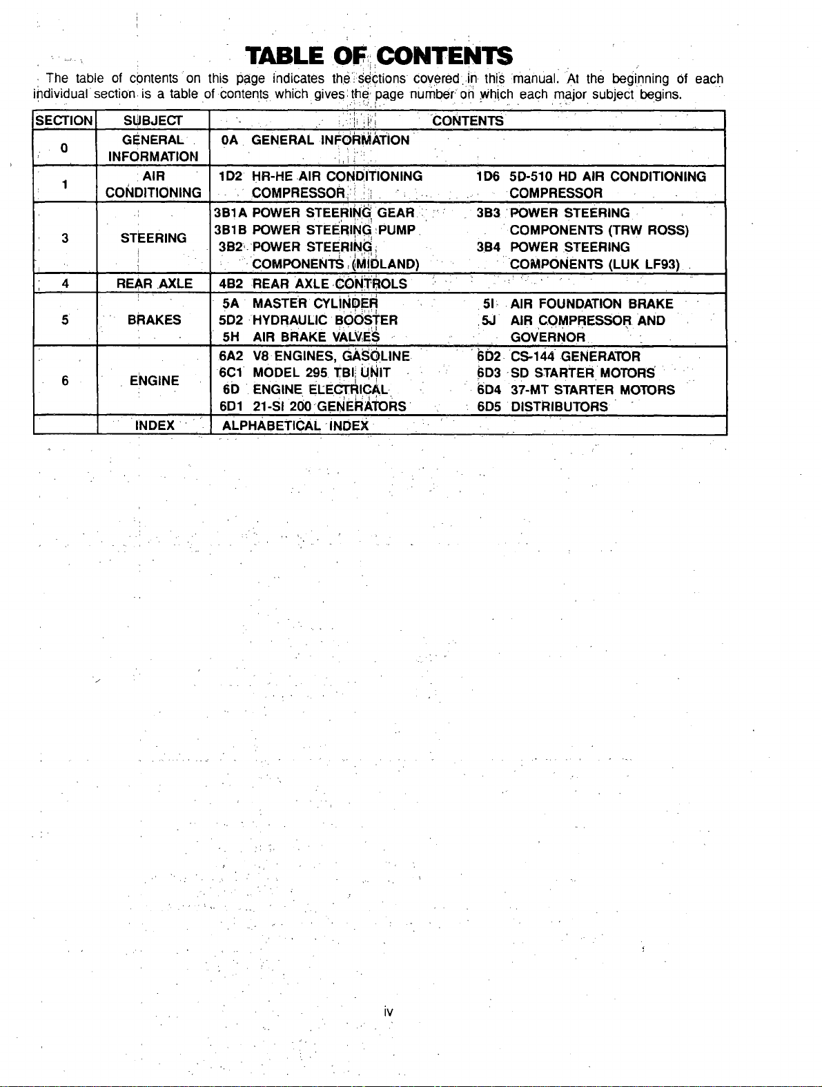
CONTENTS
SUBJECT PAGE
Special Tool Ordering Information
Service Parts Identification Label
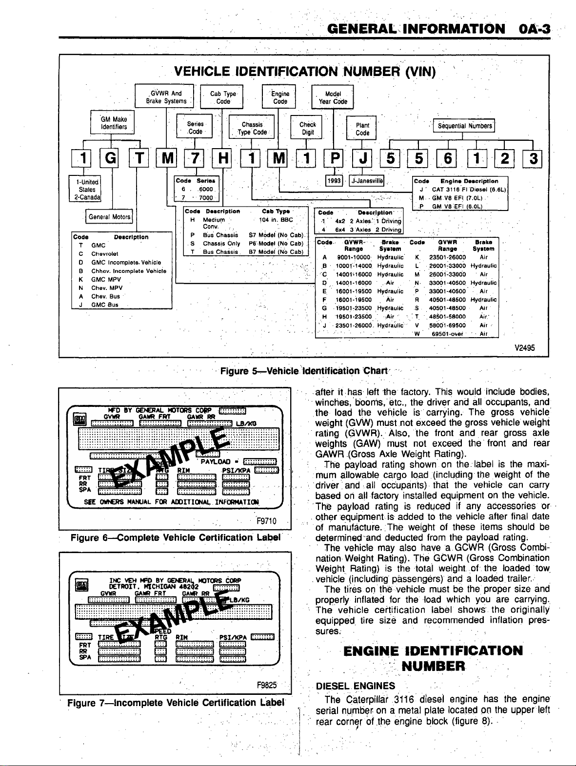
Vehicle Identification Number
....
Vehicle Certification Label..........
Engine Identification Number
....
Diesel Engines
..........
...........
Gasoline Engines
...................
Rear Axle Identification Number
Rock ell......................................
Eaton
...........................................
Transmission Identification Number
Allison
.........................................
Eaton-Full e r
..................
.............
Model Identification
......................
Metric Fasteners
...........................
Fastener Strength Identification.
Prevailing Torque Fasteners
......
Metric-English Conversion
.....
Decimal and Metric Equivalents
J1930 Word Conversion
..............
■>
OA- 1
OA- 1
OA- 2
OA- 2
OA- 3
OA- 3
OA- 4
OA- 4
OA- 4
OA- 5
OA- 5
OA- 5
OA- 5
OA- 5
OA- 5
OA- 8
OA- 8
OA- 9
OA- 9
OA- 9
SPECIAL TOOL ORDERING
INFORMATION
Special service tools that are sho n in this service
manual have tool product numbers beginning ith “J”
or “BT" are available for orld ide distribution from:
Kent-Moore
SPX Corporation
29784 Little Mack
Roseville, Ml 48066-2298
1-800-345-2233
Mon.-Fri. 8:00 p.m. EST
Telex: 244040 KMTR VR
Fax: 313-578-7375
General Motors dealers can purchase TECH 1
scan tools and accessories through Kent-Moore at
the above address and phone number. Non-General
Motors dealer repair facilities can purchase TECH 1
scan tools and accessories from Kent-Moore at the
above address or :
Sun Electric Corporation
One Sun Park ay
Crystal Lake, IL 60014
1-800-CALLSUN (225-5786)
6:45 a.m. - 7:00 p.m. CST
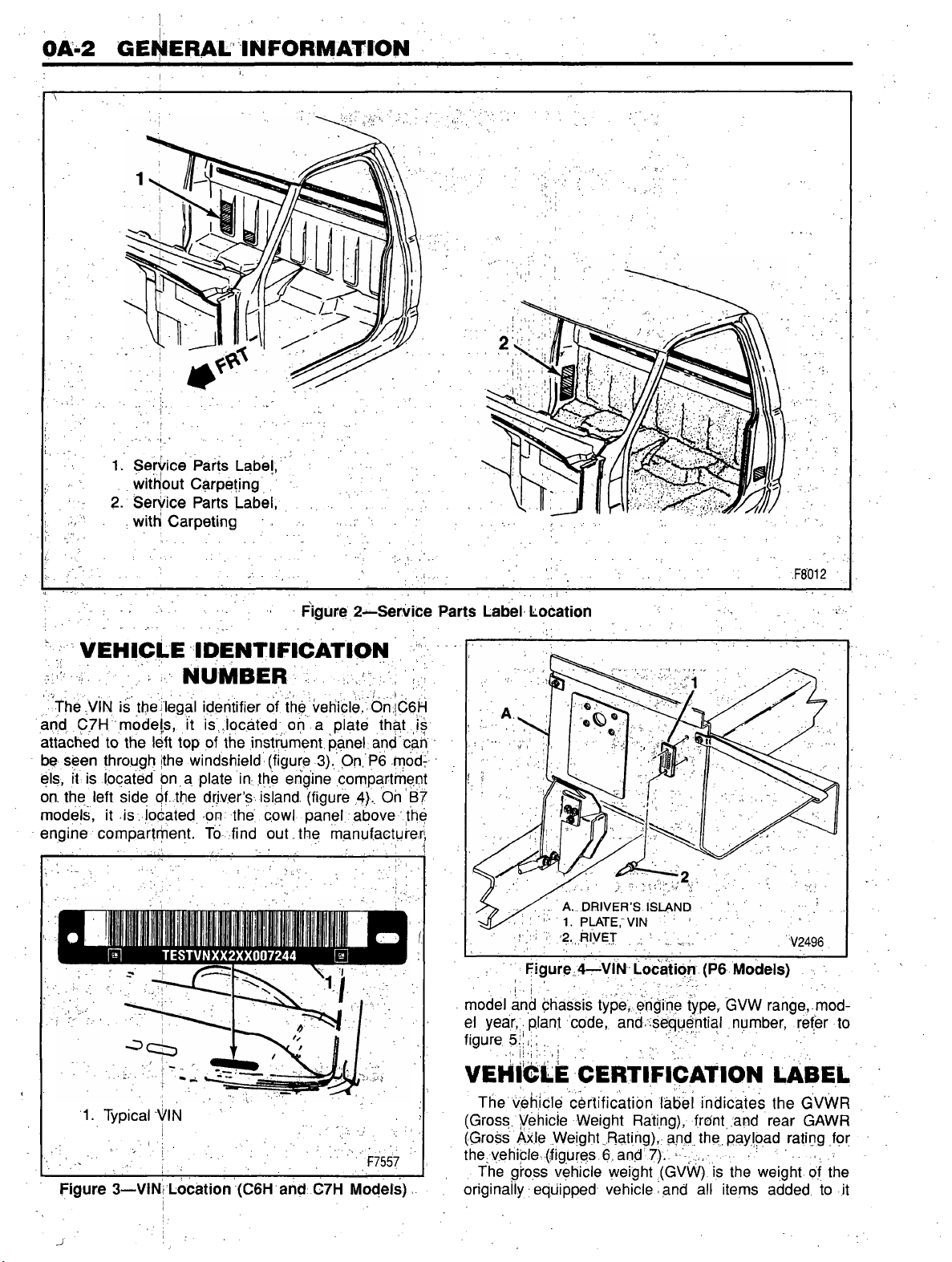
SERVICE PARTS
IDENTIFICATION LABEL
The service parts identification label is provided on all
vehicle models. On the conventional cab models (G6H
and C7H), the label is located on the side all of the
cab behind the passengers seat if the cab has carpet
panels. If the cab does not have carpet panels, the
jabel ill be located at the lo er corner of the passen
gers side of the cab all.
The label is placed on the P6 and B7 models by the
body manufacturer.
The label lists the VIN (Vehicle Identification Number),
heelbase, paint information, and all production options
or special equipment on the vehicle hen it as
shipped from the factory. ALWAYS REFER TO THIS
INFORMATION WHEN ORDERING PARTS (figures 1
and 2).
15516776
NOTICE. THIS INFORMATION IS SUPPLIED AS AN AID IN IDENTIFYING PARTS FOR SERVICE
SERVICE PARTS REQUIREMENTS FOR THIS VEHICLE MAY VARY FROM THOSE LISTED
BEFORE ORDERING ANY OK THE ABOVE PARTS. ALWAYS HAVE YOUR GENERAL
MOTORS TRUCK DEALER CHECK THIS VEHICLE'S BROADCAST SUPPLEMENT FOR
POSSIBLE PART CHANGES.
IMPORTANT: RETAIN THIS PLATE AS A PERMANENT RECORD
B5559
Figure 1—Service Parts Identification Label


 Operator's manual")