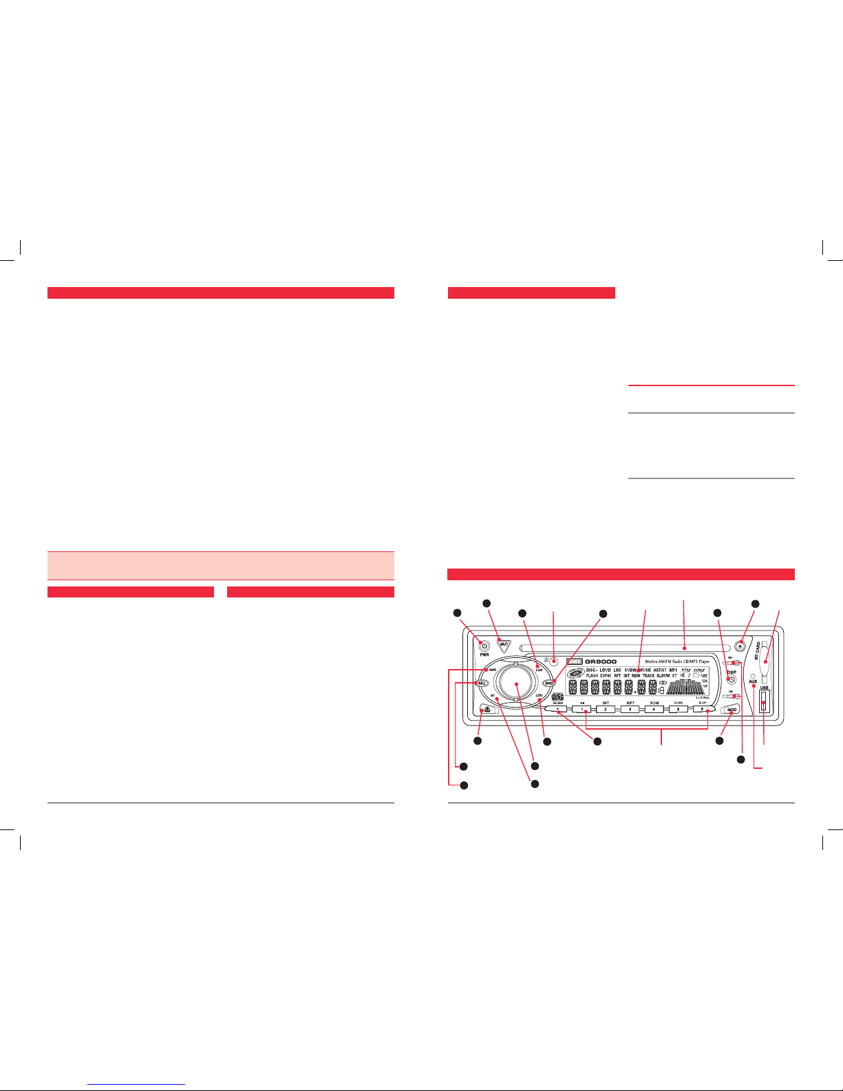
14 Scan
In the TUNER mode, press and hold the SCAN button for
3 seconds. The GR9000 will now scan the selected radio
band for all available stations, pausing briefly at each to
let you decide whether you wish to listen to this particular
station. To exit the Scan mode, press and hold the SCAN
button a second time.
Manually Selecting the Pre-Set Station Memories
Briefly press the desired station memory 1- 6. The GR9000
will jump immediately to that station and the memory
number will appear on the LCD.
CD/MP3 OPERATION
Warning: Do not insert CDs containing anything other
than standard audio or MP3 files into the disc slot. The
CD mechanism contains precision laser components which
could easily be damaged by inserting foreign objects.
Important: Because of the wide dynamic range offered
by CD systems, the difference in volume level between
very soft sounds and very loud sounds can be quite high.
For this reason we recommend that you avoid turning the
volume level up to loud when listening to very soft music or
tracks with no audio level, otherwise a sudden change to
very loud music could damage your speakers.
Inserting the CD
Remove the CD from it’s case and insert the disc face
up into the front panel aperture. The CD mechanism will
automatically draw the disc into the player and start playing
track 1.
A disc symbol is displayed on the LCD whenever there
is a CD in the player.
The symbol will
simulate rotation
whenever the
disc is playing.
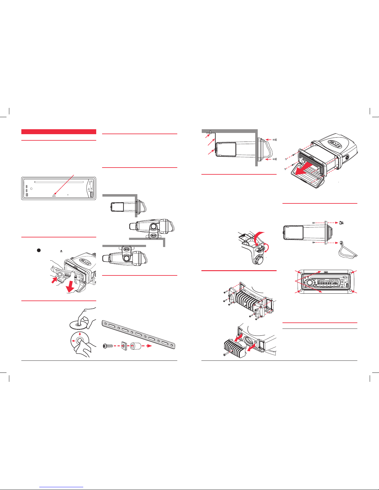
12 Ejecting a CD
Press the EJECT button to stop the CD playing and
automatically eject the disc.
11 Fast Forward/Reverse
To advance through the present track at high speed, press
and hold the button. The elapsed playing time will be
displayed and will advance rapidly. Release the button to
continue playing at the normal speed.
To reverse through the present track at high speed, press
and hold the button. The elapsed time on the display
will decrease rapidly. Release the button to continue
playing the present track at the normal speed.
11 Step to the Next Track
To step immediately to the next track, press the button
once. The next selected track will begin playing, press the
button to advance to the start of successive tracks.
To step immediately to the start of the track currently being
played, press the button once. The current track will
immediately restart. Press the button repeatedly to
locate the start of previous tracks.
11 Pause
To pause the CD, press the button once. The disc symbol
on the LCD will stop rotating when the pause function has
been selected.
Press the button again to resume playing the CD.
Repeat Play
To continually play the current track, press the RPT button.
A ‘RPT’ flag will be illuminated on the LCD when in the
repeat mode.
Press the RPT button again to return to the normal mode.
Random Play
To play tracks on the CD in a random order, press the RDM
button. A ‘RDM’ flag will be illuminated on the LCD when
in the random mode.
Press the RDM button again to return to the normal mode.
Intro-Scan
The intro-scan feature plays the first 10 seconds of each
track allowing you to identify the songs on the CD.
To select intro-scan press the INT button, the LCD will
display INT, track number and elapsed time.
Press the INT button again to return to the normal mode.
MP3 Functions
MP3 (MPEG-1 Layer 3) is a format for the compression of
audio files to approximately 8% of their original size. This
permits a large number of files to be stored on a CD-R,
CD-RW, SD Card or USB memory stick.
MP3 Music Search - To search for a particular MP3
music track, press the AMS button once, the LCD will
display ‘TRK SCH’ (track search). Press SEL, the display
will flash, then rotate the Volume control until the desired
track is found. Press SEL repeatedly until the display stops
flashing; the selected track will then play.
Precautions for CD-R and CD-RW Discs
The GR9000 will not play a CD that has not been finalised,
please refer to the instruction manual of the software
or the recorder you are using to write these CDs for the
finalisation process.
To ensure a more reliable playback, please follow GME
recommendations:
• Use CD-RWs with a speed of 1x to 4x and write with a
speed of 1x to 2x.
• Use CD-Rs with a speed of 1x to 8x and write with a
speed of 1x to 2x.
• Do not play CD-RWs that have been written to more that
5 times.
Note: If a disc contains audio CD data and MP3 files, the
GR9000 will only play which ever is first on the disc. If the
first track on the disc is an MP3 file, the unit will only play
the MP3 files from the disc, and will ignore all other files
and vice versa.
Precautions for MP3
The format of the disc must be ISO9660 level 1 or 2, or
Joliet or Romeo in the expansion format.
When naming an MP3 file, ensure the file extension is ‘.MP3’
The GR9000 will not recognise a non MP3 file even though
the name extension is ‘.MP3’.
auXI l I a rY InputS & outpu t S
To maximise the owner’s listening flexibility and pleasure
the models within the GR9000 series have several auxiliary
inputs and outputs.
FRONT PANEL INPUTS
There are standard USB and SD card inputs located on the
front panel.
When using the USB input please ensure the USB Adaptor
(Part # AD003) supplied as a standard accessory with each
GR9000 is utilised and the transparent front cover is always
fully closed to avoid any possibility of water ingress.
The are many styles and sizes of USB memory sticks and SD
cards available on the market today, however for optimum
performance GME recommends:
• Part # USB001 GME USB Memory Stick
• Part # SDC001 GME SD Card
These devices have been specifically manufactured for GME
and are available from your local GME retailer.
Aux Input
The GR9000 has a 2.5 mm stereo jack low level (1 Volt
peak to peak) audio input lines. Owners may use this input
for external audio sources that they wish to control and
play through the vessel’s stereo system.
GME offers a custom interface cable for iPod® and other
MP3 portable devices connection; Part # LE68. When using
this connection, it is necessary to use the portable device
functions to control play.
REAR OUTPUT
The GR9000 series has front and rear, right and left
channel low level audio output lines. Owners may use these
outputs to drive external booster amplifiers should they
have a particularly large vessel or require supplementary
audio output power.
When a suitable external amplifier is connected the volume,
tone and balance settings may still be controlled at the GR9000.
Warning: Extreme care should be taken when connecting
any external device to your GR9000 rear inputs or outputs.
GME strongly recommends that all such installations should
be carried out by a suitably qualified technician.
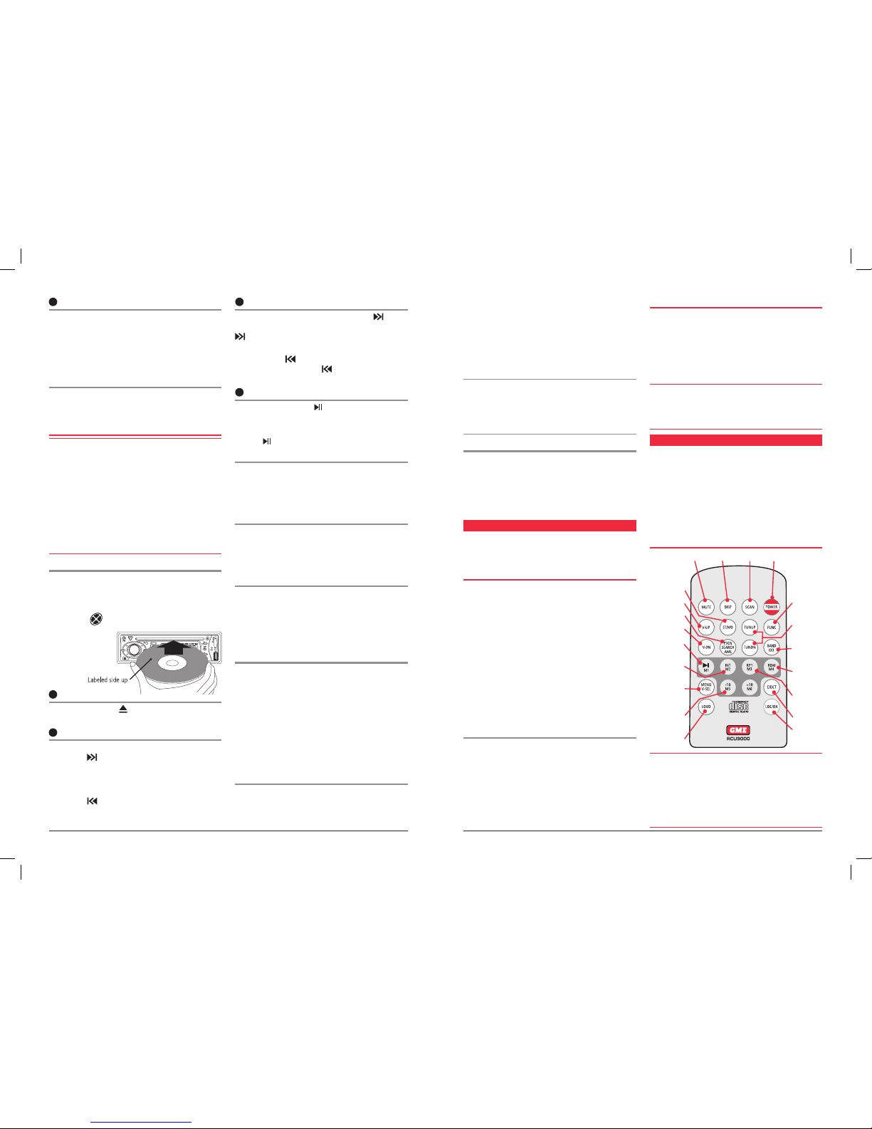
rEMotE control
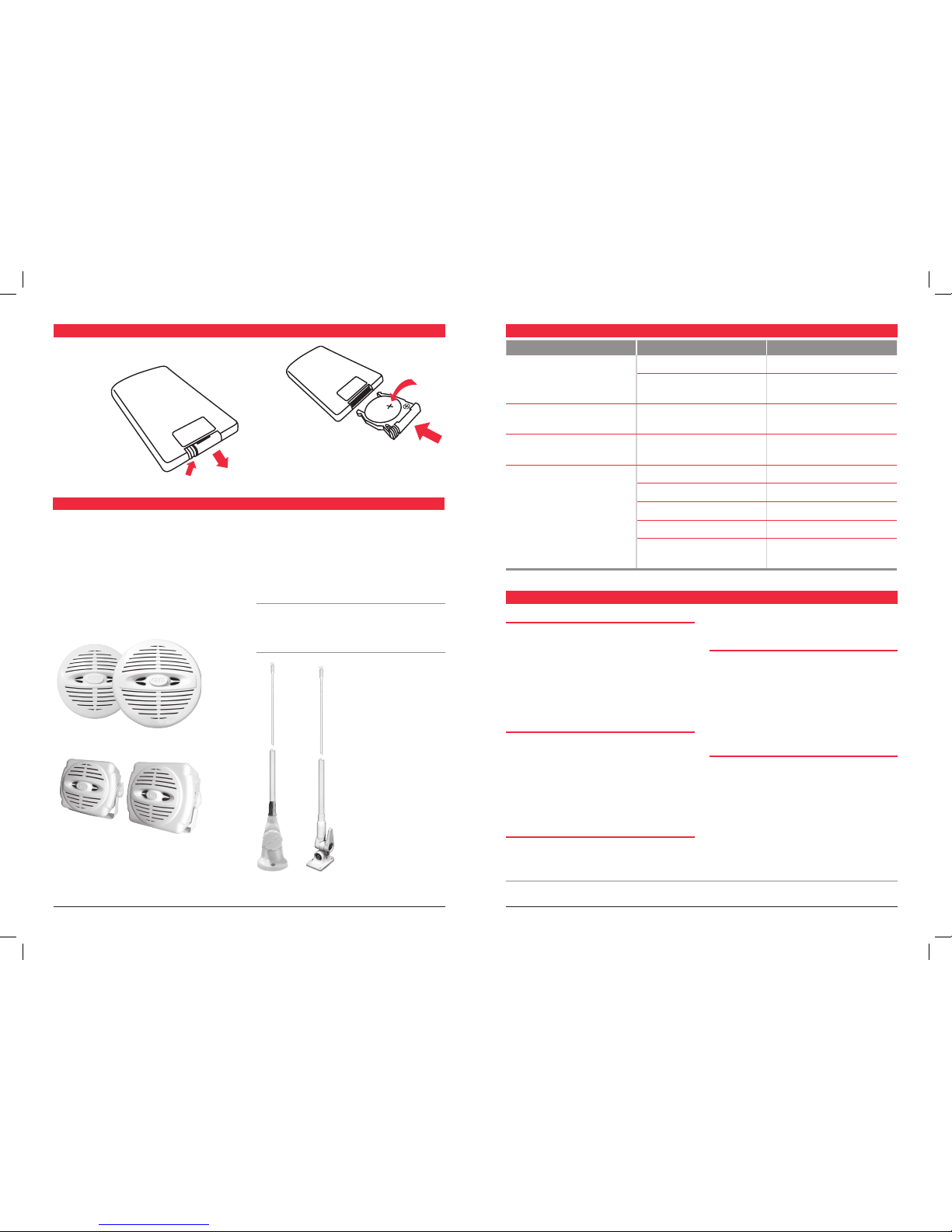
A standard accessory with the GME GR9000 is a credit card
sized wireless remote control (RCU9000). The remote will
permit the control of all major GR9000 functions from a
distance of up to 3 metres.
Ensure plastic battery protection tab is removed from the
handset before initial opereation.
Simply point the remote handset at the GR9000 and select
the required option on the keypad.
REMOTE CONTROL FUNCTIONS
Cautions
•
The remote control handset is not waterproof and should be
kept well away from both fresh and salt water at all times.
•The remote control should not be left in direct sunlight
for prolonged periods, excessive sunlight and heat
could cause damage to the keypad resulting in incorrect
operation or non function.
Mute Display Scan On/Off
Stereo/Mono
Volume up
AMS search
Volume down
Pause/Radio
memory 1
Intro Scan/
Radio
memory 2
Audio control
Select
Reverse
MP3 tracks
by 10/Radio
memory 5
Loudness
Mode/
Function
Radio tuning/
Music track
selection
Radio band/
MP3 ID
Randem
play/Radio
memory 4
Repeat play/
Radio
memory 3
CD Eject
Local/Distant