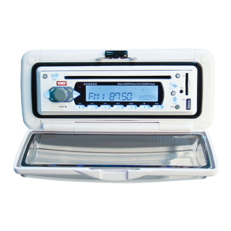
GME GR350BT User manual

GR350BT
MARINE STEREO AND MULTIMEDIA ENTERTAINMENT SYSTEM
USER MANUAL

GR350BT
2
CONTENTS
Introduction .......................................4
Key Features...............................................4
What’s in the Box...........................................4
Optional Accessories. . . . . . . . . . . . . . . . . . . . . . . . . . . . . . . . . . . . . . . . . 5
Compliance........................................5
FCC Part 15 Compliance ......................................5
Listening to FM in Your Marine Vehicle ..................6
Installation ........................................6
Installation Precautions ......................................6
Choosing a Location for your radio......................7
Mounting the Radio .........................................8
Electrical wiring and connections .......................9
Wiring Connections. . . . . . . . . . . . . . . . . . . . . . . . . . . . . . . . . . . . . . . . . . 9
DC Connections.............................................10
Hi/Low DC Supply Voltage Warnings ............................11
Antenna Installation .........................................13
Controls ......................................... 14
General Operation ................................. 15
Power On/O ..............................................15
Main Menu ................................................15
Settings Submenu. . . . . . . . . . . . . . . . . . . . . . . . . . . . . . . . . . . . . . . . . . .16
Input Source Selection .......................................19
Backlighting ...............................................19
Adjusting the Sound .........................................20

GR350BT 3
AM/FM Receiver Operation........................... 23
Tuning for Stations..........................................24
Local Mode ................................................27
Stereo/Mono Selection .......................................28
Bluetooth® Operation ............................... 30
Playing and Viewing USB Media....................... 33
Viewing Movie Files .........................................38
Viewing Photo Files .........................................41
Auxiliary Input Operation ............................ 44
Playing music through the auxiliary input ........................44
Specications* .................................... 45
General ...................................................45
FM Broadcast Receiver.......................................45
AM Broadcast Receiver. . . . . . . . . . . . . . . . . . . . . . . . . . . . . . . . . . . . . . .46
Audio Amplier .............................................46
Bluetooth .................................................47
USB Playback ..............................................47
Environmental .............................................47
External Connectors .........................................47
Multimedia support ................................ 48
Audio. . . . . . . . . . . . . . . . . . . . . . . . . . . . . . . . . . . . . . . . . . . . . . . . . . . . .48
Video.....................................................48
Photo ....................................................49
Trouble-Shooting .................................. 49

GR350BT
4
INTRODUCTION
Congratulations on purchasing your compact GME GR350BT series marine stereo
and multimedia entertainment system.
The GR350BT is a state-of-the-art Marine Entertainment System combining
an AM/FM Radio with Bluetooth® audio streaming that can be paired with any
smartphone, tablet or compatible device. An auxiliary input socket allows direct
audio connection to generic MP3/WMA media players that do not support
Bluetooth streaming.
The GR350BT Marine Multimedia Entertainment System has been developed
utilising a combination of the very latest in digital electronic technology, and the
design expertise gained by GME engineers over several decades of marine product
development. The design and engineering of the radio ensures that your radio
is protected against any harsh marine environment and ensures many years of
reliable service.
KEY FEATURES
• Bluetooth streaming
• USB/AUX inputs
• Built-in AM/FM tuner
• 4 X 40W Speaker Outputs
• Full-color 2.7” TFT LCD Display
• Water-resistant
WHAT’S IN THE BOX
• GR350BT AM/FM Marine stereo
• Mounting hardware
• Mounting template
• DC power lead
• Speaker leads
• Quick start guide

GR350BT 5
• Ingress protection to IPX5 (excludes external connectors)
• Conformally coated PCB’s for the harsh marine environment.
• UV Stabilized Plastics
• Available in black or white.
OPTIONAL ACCESSORIES
• Range of GME Speakers
• Range of GME Marine AM /FM Antennas
• Auxiliary input interface cable - LE74
COMPLIANCE
This device complies with AS/NSZ 61000.6.3:2007
FCC PART 15 COMPLIANCE
This equipment has been tested and found to comply with the limits for a Class
B digital device, pursuant to part 15 of the FCC Rules. These limits are designed
to provide reasonable protection against harmful interference in a residential
installation. This equipment generates and can radiate radio frequency energy and
if not installed and used in accordance with the instructions, may cause harmful
interference to radio communications.
However, there is no guarantee that interference will not occur in a particular
installation. If this equipment does cause harmful interference to radio or
television reception, which can be determined by turning the equipment o and
on, the user is encouraged to try to correct the interference by one or more of the
following measures:
• Reorient or relocate the receiving antenna.
• Increase the separation between the equipment and receiver.
• Connect the equipment into an outlet on a circuit dierent from that
to which the receiver is connected.
• Consult the dealer or an experienced radio/TV technician for help.

GR350BT
6
LISTENING TO FM IN YOUR MARINE VEHICLE
The majority of FM broadcasts are music programs. Compared with AM signals,
FM signals have a wider dynamic range, are relatively immune to noise and
provide distortion-free reproduction.
FM programs are broadcast for local reception and may not be heard satisfactorily
at distant locations. To enjoy FM programs at their best, it is important that you
tune to a station that is broadcasting in your locality.
FM signals can reect from solid objects such as buildings or hills. If these
reected signals are received along with signals that are arriving directly from
the transmitter, they may mix together to produce what is known as ‘multipath
distortion. This distortion is heard as noise. Often, moving as little as 1 meter from
your position will correct this problem.
FM signals travel in straight lines. However, because the signals are reected from
or absorbed by large solid objects, a signal ‘shadow’ may be present behind the
object which may result in poor reception in that area.
INSTALLATION
INSTALLATION PRECAUTIONS
• If you are connecting your GR350BT radio for the rst time, or
have just reconnected your boat battery and you are experiencing
problems with the unit’s operation, we recommend you reset
the unit. The reset function is accessed through the Main MENU
SETTINGS option See PAGE X for details.
• The pre-set station memories and clock time are retained only while
the power lead is connected to the Vessels DC power source. If the
Power lead is disconnected or switched o at the master switch or
the unit is removed from the vessel, the station memories will be
lost, and the clock will need to be reset.

GR350BT 7
CHOOSING A LOCATION FOR YOUR RADIO
The GR350BT is designed for in-dash mounting in an accessible position near your
vessel’s steering position. Keep the following points in mind when choosing a
location:
• Minimise excessive exposure to continuous rain or spray.
• Minimise expose to excessive vibration or continuous direct
sunlight.
• Allow room behind the radio to run the DC Lead to the power
source.
• Allow a free ow of air around the heat sink on the back of the
radio.
• To avoid interference to compasses, ships autopilot sensors etc, the
GR350BT radio should be mounted at least 300 mm away from such
devices.
The GR350BT multimedia hub can be mounted nearby or installed in a separate
location inside the cabin using an extension lead. The cover on the multimedia hub
should remain accessible to allow access for connecting your MP3 music source
USB memory stick, or generic MP3 player.

GR350BT
8
MOUNTING THE RADIO
When mounting your radio using the mounting plate, please refer to the diagram
below.
Source Unit
Trim Bezel
Mounting Screws
Panel
Select a suitable mounting location then examine behind the panel to determine
that there is sucient access for routing the cables and tting the mounting
screws. For panels of 6 – 9 mm thickness such as aluminum, plywood or
berglass, the unit can be mounted using the 12 mm screws supplied (refer the
diagram above).
1. Cut out a circular hole 77mm (3 inches) in diameter on your mounting
location. Keep in mind that at least 95mm (3.75 inch) depth is needed
to mount the radio.
IMPORTANT: Do not mount this unit where it can be submerged in
water.
2. Use the supplied mounting template to mark and drill holes for the
four mounting screws.
3. Slide the mounting plate over the backside of the unit and secure with
the supplied screws.
4. Press on the Trim Bezel to the front side of the unit.
5. Plug in all wiring harnesses and cables. Refer the wiring diagram in
this guide.

GR350BT 9
ELECTRICAL WIRING AND CONNECTIONS
When connecting the GR350BT to your vessels electrical system, please refer to
the wiring and rear connections diagrams in the following sections.
CAUTION: The GR350BT is designed for vessels with a 12 Volt DC negative (−)
ground (earth) electrical system only! Reverse polarity or over-voltage connection
will result in internal damage to your unit, voiding the warranty and requiring
servicing by qualied personnel.
WIRING CONNECTIONS
USB
Radio antenna
Front right speaker
Front left speaker
Rear right speaker
Rear left speaker
Auxiliary input
DC Cable
DC Cable
Fuse 15 Amp
Black - ve
Red + ve
12 V battery

GR350BT
10
DC CONNECTIONS
Please refer to the wiring diagram in the previous section.
1. Connect the RED power lead to the positive (+) side of the battery or
to an accessory point in the vessel or vehicle’s fuse box that provides
a +12 Volt DC connection.
2. Connect the BLACK power lead to the negative (-) side of the battery
or to a ground point in your vessel or vehicle.
IMPORTANT NOTES:
• The RED power lead is tted with a 15 amp fuse. If the fuse blows,
use only a standard 15 amp (3AG) fuse as a replacement. Use of a
higher rated fuse or a slow-blow type could result in damage to your
radio which would void the warranty. If the fuse blows a second
time, please contact your GME dealer for advice.
• Your GR350BT radio is able to maintain its memories and clock time
when it is switched o by drawing power directly from your battery
via the RED Lead. Although the memory backup current is very
small (about 10 mA), it could eventually discharge your battery if left
connected indenitely. The time taken to completely discharge your
battery could vary depending on its amp-hour rating and battery
condition.
• If you do not run your boat’s motor regularly or your battery is
not kept charged between outings (e.g. solar or wind charger), we
recommend you disconnect the RED lead each time you secure
or trail your boat. This is easily done by connecting the lead via a
master switch, which can be switched o after each outing. This
will mean you will lose all your pre-set station memories and clock
settings.

GR350BT 11
HI/LOW DC SUPPLY VOLTAGE WARNINGS
In the cases where the supply voltage EXCEEDS 18.0 Volts or FALLS Below 7.0
VOLTS the GR350BT displays the following warnings:
If either of these appear, it indicates a problem with your power supply. Please
switch the radio o and check your vessels electrical system.
SPEAKER CONNECTIONS
This section details the ideal way to connect speakers to your GR350BT radio:
• Connect the speakers to the respective FRONT (LEFT/RIGHT) and
REAR (LEFT/RIGHT) speaker y-leaded sockets at the back of the
unit.
Note that the speaker sockets are tted with protective covers to
protect against water ingress when not in use.
• The GR350BT radio is supplied with four 3.5 mm speaker adapter
leads which are designed to accept the standard bullet connectors
commonly found on most marine and automotive stereo speaker
cables. The plugs on the speaker adapters plug into the matching
sockets on the speaker y-leads attached to rear of the radio. The
speaker adapters are labeled and should be matched with the labels
on the speaker socket y-leads to ensure correct speaker phasing.
Incorrect polarity (speaker phasing) will result in a signicant
reduction of bass response and stereo eect.
• When connecting the speakers, observe the correct speaker polarity
by matching the white stripes on the speaker leads with the white
stripes on the adaptor cable as shown in the connections diagram
that follows. Incorrect polarity (speaker phasing) will result in a
signicant reduction of bass response and stereo eect.

GR350BT
12
• Connect all four speakers as shown in the connection diagram that
follows.
• Adjust the BALANCE and FADER controls for the required LEFT/
RIGHT and FRONT/REAR balance.
• If you wish to connect only two speakers, connect these to the
Front speaker sockets and adjust the Fader control to the FRONT
speakers.
• To protect against water ingress, replace the protective covers on
any unused speaker sockets.
NOTE:
1. The GR350BT is a 4-speaker system that requires two separate wires for each
speaker. Do not touch the speaker wires together or allow them to touch other
wiring or the vessel ground (earth)..
2. The use of speakers with an impedance of LESS than 4 Ohms is NOT
recommended, as they will cause excessive loading of the GR350BT’s output
circuit and may result in the radio overheating. A range of GME speakers are
available from your local GME retailer.
GR350BT Radio
L
R
11
1
Bullet Connectors
White Stripe
Speakers
SPEAKER ADAPTOR LEADS
• After the external stereo speakers are connected, you can adjust the
audio between the LEFT/RIGHT and FRONT/REAR speakers using the
Balance and Fader functions available via the Control Knob.

GR350BT 13
ANTENNA INSTALLATION
This section provides instructions on the ideal way to install and connect the
antenna for your radio.
• It is essential to select a good quality AM/FM antenna. A poor
quality antenna will not provide good performance.
For information on suitable AM/FM antennas, please refer to
the GME website: https://www.gme.net.au/boating-and-shing.
aspx?f=AM/FM-and-Mobile-Phone or contact your Local GME dealer.
• Mount the antenna in a position as high as practically possible to
ensure good reception, especially in areas of low signal strength.
• When installing the antenna, ensure a minimum clearance of around
20 cm from bow or stern rails or windscreen frames etc.
• Ideally, place the antenna at least 1 meter away from two-way radio
antennas to minimise interference from radio transmissions.
Connecting the antenna to your radio:
Plug the antenna lead into the yleaded antenna socket on the rear of the unit.
The socket accepts a standard AM/FM radio bayonet connector.
NOTE: The antenna socket is not waterproof.
Noise Suppression
The inherent design of FM radios results in a high level of resistance to ignition
and electrical interference however electrical interference on AM radio can be
almost impossible to eliminate. To help minimise interference, take extra care
during the installation.
• Route the DC battery leads, the antenna lead or any accessory wires
away from the engine compartment, ignition or alternator wiring. A
suppression kit may also help to reduce excessive electrical noise.
Contact your dealer or radio installer for more information.
• If the interference you are experiencing is from other nearby
electronic equipment such as a depth sounder, try to keep the
depth sounder’s DC leads and transducer cable well away from your
GR350BT’s wiring.

GR350BT
14
Waterproong the connections
• After installation, the power, speaker and antenna connectors
should be wrapped in waterproof tape (or similar) to minimise the
risk of corrosion or water damage.
• Do not use normal electrical tape as this will not provide an
adequate seal against water.
• The connectors should be positioned where they are not directly
exposed to the elements.
CONTROLS
The controls and buttons you can use on the radio are displayed in the graphic
below.
CH
MENU
CH
SRC BND MUTE
LCD Screen
Control Knob
(Rotate to vary;
Press to conrm)
Tune Down (Radio) /
Previous Track (Media)
Tune Up (Radio) /
Next Track (Media)
Mute (Audio) /
Adjust Display Backlight
Pause/Play (Media) /
Select Band (Radio)
Next Pre-set
Broadcast Station
Menu / Return
Input Source Selection /
Power On/O
Previous Pre-set
Broadcast Station

GR350BT 15
GENERAL OPERATION
POWER ON/OFF
• To turn the GR350BT radio on, press the SRC button. The unit will
display the GME logo, and resume in the mode and settings that
were selected when last turned o.
• To turn the radio o, press and hold SRC button. The unit will
display ‘Good bye / Power O Now’, and switch o.
MAIN MENU
To access the main system menu (home screen):
1. Briey press the Menu button. The main menu will be displayed with
the current source highlighted, as illustrated below.
2. Rotate the control knob, or briey press the Tune Down or Tune
Down buttons to select between the following sources: Multimedia,
Radio, Bluetooth, Aux In, Settings.
3. Press the control knob to conrm the selection. The radio will switch
to the selected source and return to the normal display
4. To exit the menu screen at any time briey press the Menu button.

GR350BT
16
SETTINGS SUBMENU
Using the procedure above, select Settings from the main menu to set the System
Time, Time format (12/24 Hours), keypress beep on/o, check battery voltage,
restore factory settings, and to conrm the software version.
TO ACCESS THE SETTINGS SUBMENU
1. Briey press the Menu button. The main menu will be displayed with
the current input source highlighted.
2. Rotate the control knob to highlight Settings.
3. Briey press the control knob to display the Settings sub-menu with
the available options.
SETTING THE SYSTEM (CLOCK) TIME:
1. Access the Settings sub-menu as detailed in the previous section.
2. Briey press the control knob to highlight the current system time.
SETTING
System Time 12.00AM
Time Format 12/24 Format
Beep ON
Voltage 13.8V
Restore Factory Seng NO
Version GR350_M0.1.0
3. Rotate the control knob to adjust the Hours.

GR350BT 17
4. After setting the Hours, briey press the control knob. The Minutes
will be highlighted in yellow.
5. Rotate the control knob to adjust the minutes.
6. Briey press the control knob to conrm and store the time.
7. Briey press the Menu button twice in succession to return to the
normal display, or allow the Settings screen to timeout after 10
seconds.
NOTE: The time setting will be retained as long as the 12V power source remains
connected. If the 12V power source is disconnected, the time setting will be lost
and will need to be reset once power is restored.
SETTING THE TIME FORMAT (12 or 24 Hour)
1. Access the Settings sub-menu.
2. Rotate the control knob to scroll to Time Format.
3. Briey press the control knob to highlight the current time format.
4. Rotate the control knob left or right to select between 12 or 24 Hour
format.
5. Briey press the control knob to conrm your selection.
6. Briey press the Menu button twice in succession to return to the
normal display, or allow the Settings screen to timeout after 10
seconds.
SETTING THE SYSTEM (CLOCK) TIME:
1. In Settings, rotate the control knob to highlight System Time.
2. Press the control knob to highlight the time.
3. Rotate the control knob left or right to adjust the Hours.
4. When the Hours have been set, briey press the control knob. The
‘Minutes’ will be highlighted.
5. Rotate the control knob to adjust the Minutes.
6. Briey press the control knob to conrm and store the time.

GR350BT
18
7. Briey press the Menu button twice in succession to return to the
normal display.
Note: The time setting will be retained as long as the 12V power source remains
connected. If the 12V power source is disconnected, the time setting will be lost
and will need to be readjusted once the power is restored.
SELECTING KEYPRESS BEEP TONE:
By default, the GR350BT radio provides a conrmation beep whenever a front
panel button is pressed. If preferred, the beep can be disabled.
To disable/enable the beep:
1. Access the Settings sub-menu.
2. Rotate the control knob to highlight ‘Beep’.
3. Briey press the control knob, Beep On/O will be highlighted.
4. Rotate the control knob to select between ON or OFF.
5. Briey press the control knob to conrm your selection.
6. Briey press the Menu button twice in succession to return to the
normal display or allow the Settings screen to time out after 10
seconds.
VOLTAGE
The GR350BT radio continuously monitors and displays the DC supply (battery)
voltage. This feature is for utility and is not user adjustable.
Restore Factory Setting (SYSTEM RESET):
When installation is complete, it is recommended to reset the radio to ensure it is
ready to operate for the rst time.
If at any time the controls do not seem to work (after replacing the vessel’s
battery, for example), perform a reset which will restore the radio to its default
factory settings.
NOTE: By performing a system reset all station preset memories, tone control
settings, and clock time will be lost and will need to be re-entered.

GR350BT 19
1. Access the Settings sub-menu.
2. Rotate the control knob to highlight ‘Restore Factory Setting’.
3. Briey press the control knob. Restore factory setting ‘NO’ will be
highlighted.
4. Rotate the control knob to select ‘YES’.
5. Briey press the control knob to conrm your selection. The radio will
then be restored to its default factory settings.
6. Briey press the Menu button twice in succession to return to the
normal display, or allow the Settings screen to time out after 10
seconds.
VERSION
This represents the current rmware version of the GR350BT radio, and is for
reference only. It is not user adjustable.
INPUT SOURCE SELECTION SRC
Press the SRC button repeatedly to cycle through the radio’s available input
sources. The icon for the selected input source will be displayed. Inputs include
AM/FM tuner, USB Flash Drive, Auxiliary input and Bluetooth®.
NOTE: If no USB Memory Drive is connected, The radio will automatically skip over
that input source, which cannot be selected. Whenever the radio is switched on, it
will automatically attempt to return to the input source that was last selected.
BACKLIGHTING
While the GR350BT is switched on, press and hold the Mute button to change the
brightness of the Screen Backlighting. There are two levels of display backlighting
available: Bright (default) and Dim.

GR350BT
20
ADJUSTING THE SOUND
The GR350BT radio’s volume, bass, midrange, treble, balance, fader, loudness and
graphic equaliser settings are adjusted sequentially using the large control knob.
When adjusting an audio parameter, the corresponding icon will appear on the
display. If no adjustments are made for 5 seconds, the icon will time out to the
normal display.
ADJUSTING THE VOLUME
Rotate the control knob clockwise to increase or decrease the volume. The volume
level is displayed on the LCD in values from 0 (min) to 45 (max).
NOTE: It is not recommended to operate the GR350BT at very high
(> 40) volume levels for extended periods of time as this may cause
the unit to overheat and possibly shut down in order to protect the
internal circuitry. If shutdown occurs, allow the unit to cool suciently
before switching it back on.
ADJUSTING THE BASS
1. Briey press the control knob repeatedly until the Bass icon is
displayed.
2. Rotate the control knob to adjust the bass. The selected setting will
be displayed on the LCD in values from −10 (min) to +10 (max). For a
at bass response, select 0 (Zero).
ADJUSTING THE MIDRANGE
1. Briey press the control knob repeatedly until the Mid icon is
displayed.
2. Rotate the control knob adjust the Midrange. The selected setting will
be displayed on the LCD in values from −10 (min) to +10 (max). For a
at Midrange response, select 0 (Zero).
Other manuals for GR350BT
1
Table of contents
Other GME Marine Audio manuals