GME GR9220W User manual

GR9200
SERIES
INSTRUCTION MANUAL
MARINE STEREO SYSTEMS
GR9220W • GR9220B
GR9240W • GR9240B

PAGE 2 INSTRUCTION MANUAL GR9200 SERIES
CONTENTS
GME STRONGLY RECOMMENDS THAT YOU KEEP THIS MANUAL
IN A SAFE PLACE FOR FUTURE REFERENCE
ACCESSORIES SUPPLIED . . . . . . . . . . . . . . . . . . . . 2
FEATURES...............................3
INTRODUCTION ..........................3
Product Description and Model Designators . . 3
CONTROL LOCATIONS. . . . . . . . . . . . . . . . . . . . . . 4
INSTALLATION ...........................5
Precautions ..........................5
Removing and Refitting the Face Panel ......5
Handling Compact Discs .................5
Moisture Condensation..................5
Location .............................5
Flush Mounting - GR9220................6
Bracket Mounting - GR9240 ..............6
Flush Mounting - GR9240................7
Removing Clear Cover . . . . . . . . . . . . . . . . . . 7
ElectricalWiring.......................8
Fuse Replacement.....................10
OPERATION ............................10
General Functions.....................10
Radio Operation ......................10
CD/MP3 Operation ....................11
CONFIGURATION MENU TABLE..............13
AUXILIARY INPUTS & OUTPUTS..............14
Front Panel Inputs.....................14
Aux Input ...........................14
RearOutput.........................14
OPTIONAL ACCESSORIES...................15
GR9200 TROUBLE SHOOTING GUIDE . . . . . . . . . 16
SPECIFICATIONS .........................17
STANDARD COMMUNICATIONS
CONTRACT WARRANTY . . . . . . . . . . . . . . . . . . . 18
GME AFTER SALES SERVICE . . . . . . . . . . . . . . . . 18
ACCESSORIES SUPPLIED
The GR9200 is supplied with the following
standard accessories:
• Mainunit
• Rubbermountinggasket-GR9220only
• USBadaptor
• DC/speakercableharness
• Mountingbracket-GR9240only
• Gimbalknobs(2)-GR9240only
• Topandbottomcoverllstrip
• Protectivecasefordetachablefacepanel
• Flushmountsupportkitandtemplate
• Spareushmountscrewcaps(4)
• Instructionmanual
Pleaseimmediatelycontactyourpointofpurchaseifanyof
these components are missing.

GR9200 SERIES INSTRUCTION MANUAL PAGE 3
CongratulationsonyourpurchaseoftheGMEGR9200
seriesMarineStereosystem,arguablythenestmarine
audioproductavailabletoday.YourGR9200hasbeen
designedwithboththemusicbuffandboatownerinmind.
Bywayofahostoffeaturesneverbeforefoundinamarine
stereosystem,theGR9200offersmusicenthusiaststhe
samelevelofaudioqualitynormallyreservedforhighend
homesystems.
TheGR9200serieshasbeendevelopedutilisingthevery
latestindigitalelectronictechnologycombinedwiththe
designexpertisegainedbyGMEengineersoverseveral
decadesofmarineproductdevelopment.Withallcircuitry
conformallycoated,exposedmetalworkprotectedagainst
the harsh marine environment and installed in a UV
stabilisedwaterresistantpolycarbonatehousing,the
GR9200willensuremanyyearsofreliableservice.
Everattentivetocustomerneeds,GMEofferstheGR9200
in two discrete configurations. For the smaller vessel where
exposuretotheelementsisgreater,thefullyenclosed
GR9240isideal.Forlargercruisersoryachtswhere
bulkheadinstallationisthepreferredoption,theGR9220is
the perfect solution.
TheGR9200hasalltheattributesexpectedfromasuperior
stereosystem,furthermore,inclusionsofSDandUSBinputs
andiPod®compatibility,willensuretheGR9200
isdestinedtobecomethestandardbywhichallmarine
stereosystemsaremeasured.
Pleasereadthisinstructionbookletcarefully,dropinyour
favouritemusicselection,sitbackandenjoythe
sounds that cannot fail to impress even the most
critical audiophile.
• MP3viaCD/USB/SDcardandauxiliaryinput
• Detachablefrontfacepanel
•4 x 45 Watt power output
• ConformallycoatedPCBsforprotectionagainst
the harsh marine environment.
•Rugged and weatherresistantcase,madefrom
high impact UV protected plastics.
• Multiplemountingoptions-ushor
bracketmountdependingonmodel.
•Backlit LCD screen
• iPod*connectivityviaoptional
interconnectcable
• Availableinblackorwhite
*iPodisatrademarkofAppleComputerInc.,registeredintheU.S.and
other countries.
INTRODUCTION
FE AT URES
TheGR9200seriesisavailableinthefollowingformats:
GR9220W (White) and GR9220B (Black)
Designedforushmountingintobulkheadsordashboards
wheretherearcaseoftheproductisnotexposedtoany
water ingress or moisture. The GR9220 has a semi open
rearcasetopermitheatdissipationgeneratedbyoperating
thesystemathighvolumesforextendedperiodsoftime.
GR9240W (White) and GR9240B (Black)
Designedwithafullyenclosedwaterproofmarinehousing
toenableinstallationonopenboatsorinareaswhere
occasionalwaterexposureispossible.TheGR9240utilises
GME’s unique ‘Big Gun’ custom heat dissipater to avoid
anyoverheatingorcomponentdamageinsituationsof
prolonged use at high volumes or in areas of high
ambienttemperatures.
PRODUCT DESCRIPTION AND MODEL DESIGNATORS

PAGE 4 INSTRUCTION MANUAL GR9200 SERIES
GR9200
4x45
Watts
CONTROL LOCATIONS
810 6
12
15
3
13
47
2
9
11
1
5
14
D-DN
1Power On/Off
2Volume Control
3Select
4Loudness
5Mute
6Clock/Time Selector
7Mode Switch
8LOC/DX Selector
9Stereo/Mono
10 Band Selector
11 Tuning/Selecting Tracks
12 Eject
13 Auto Music Search
14 Scan
15 Release Button
16 LCDDisplay
17 CD Slot
18 AuxiliaryInput
19 USB Input
20 PresetmemoryKeysandCD/MP3functions.
21 SD Card Input
16
17
18
19
20
21

GR9200 SERIES INSTRUCTION MANUAL PAGE 5
INSTALLATION
PRECAUTIONS
IfyouareconnectingyourGR9200forthersttimeorhave
justreconnectedyourboatbatteryandyouareexperiencing
problemswiththeunit’soperation,wesuggestyoutry
resettingtheunit.Theresetbuttonislocatedunderthe
removablefacepanel(seebelowforinstructions).Gently
presstheresetbuttonwithapapercliporsimilarobject.
You can then refit the face panel.
The preset station memories and clock time are retained
onlywhiletheyellow‘Memory’leadisconnectedtoa
continuous+12VDCsupply(seeElectricalWiringsection).
Ifthebatteryisdisconnectedorswitchedoffatthemaster
switch,ortheunitisremovedfromthevessel,thestation
memorieswillbelostandtheclockwillneedtobereset.
REMOVING & REFITTING THE FACE PANE
L
Beforeremovingthefacepanel,turntheunitOFFby
pressing the Powerbutton.
1. Press the 15 releasebutton to release the
left hand end of the face panel.
2.Liftthefacepanelouttowardsyou.
3.Afterremovingthefacepanel,placeitinsidethe
supplied case to protect it from damage.
To refit the face panel
1. Slide the right hand end of the face panel into position
toengagethelockingtabs.
2. Press the left hand side into place until it clicks.
HANDLING COMPACT DISCS
• HandletheCDbyit’sedge,avoidtouchingthe
disc surface.
• StoreyourCDsawayfromdirectsunlightorheatsources.
KeepingtheCDinit’soriginalcasewillhelptokeep
itat.
• CleantheCDwithasoftclothfromthecentretothe
outeredge,(seediagram)ratherthaninacircular
motion. Do not use solvents.
MOISTURE CONDENSATION
YourGR9200usesopticallasertechnology.Occasionally
damporhumidconditionsmaycausecondensationto
appearonthelensesinsidetheunit.Shouldthisoccur,the
unitmightnotoperatecorrectly.SimplyejecttheCDand
leave the unit turned on for a while until the
moisture evaporates.
LOCATION
TheGR9200isavailableinarangeofmounting
congurationstoenableittobeinstalledinthemost
convenient position. GME recommends that the unit should
bemountedinapositionthatisfreefromdirectsunlight
andexcessivevibration.
Reset Button
Note.TheGR9200shouldnotbemountedatangles
greaterthan30°aboveorbelowthehorizontal.

PAGE 6 INSTRUCTION MANUAL GR9200 SERIES
FLUSH MOUNTING - GR9220
TheGR9220canbeneatlyushmountedintoapanelor
bulkheadsothatjustthecontrolsandtheprotectivecover
arevisible.
Usingthetemplateprovided,selectasuitablelocationona
panelorbulkhead.Examinebehindthepaneltodetermine
thebestmethodofsupport.Ifthethicknessofthepanelis
notsufcienttosupporttheunit,itwillbenecessarytouse
thestrapsupplied(seefollowingdiagrams).
BRACKET MOUNTING - GR9240
1.AttachtheGR9240tothemountingbracketusingthe
twogimbalknobs.
2.TemporarilypositiontheGR9240inthedesiredlocation
androughlymarkthelocationofthebracketedges.
Now,removetheunitfromthebracketandreposition
thebracketatthedesiredlocationtomarkthemounting
hole positions.
3.Screworboltthebracketintoposition.Themounting
methodwilldependonthematerialtowhichthebracket
isbeingattached.
4.RettheGR9240intothebracketandadjusttothe
desiredanglebeforetighteningthegimbalknobs.
5. Complete the antenna lead and electrical wiring
asdescribedlater.
GR9240 On-Dash Mounted
Screw
Strap
Screw
Screw
Screw
Rubbergasket
Flush Mount
Support Strap
Rear centre Screw with Spacers
*Usetherubbermountinggasketsupplied.Placethegasket
betweentheplastichousingandthemountingsurface.Thiswill
improvethecontactbetweenthemountingsurfaceand
stereo housing.
30o
30o
GR9240 Overhead Mounted
GR9220 Flush Mounted

GR9200 SERIES INSTRUCTION MANUAL PAGE 7
GR9200
4x45
Watts
D-DN
Foroverheadmounting,theGMElogosonthesideof
eachbracketcanberotatedasshownright.
FLUSH MOUNTING - GR9240
AlthoughtheGR9240isabracketmountedunit,itcanbe
ushmountedbyfollowingthedisassembly
instructionsbelow.
1. Removethe4screwsfromeachcableclamp
panel at rear.
2. Remove the screw from the centre of the heat
dissipater and remove.
3. Remove the 4 screw caps and 4 screws from the front
caseandslidetheunitoutcompletely.
YourGR9240cannowbeushmounted.Replacement
screwcapshavebeenprovidedtocovertheexposed
screw heads.
REMOVING THE CLEAR COVER
IfyourGR9200willbemountedinadryprotectedlocation
awayfromthepossibilityofwateringress,thefrontclear
covercanbepermanentlyremoved.
1.Removethe4screwsfromthetopandbottominside
edgeofthemountframeasshownabove.Remove
toplatchassemblyandclearcover.
2. Fit replacement fill strips as supplied into top and
bottomframeedges.
3.Mountyourunitintothebulkhead.Usethescrewcaps
supplied to cover screw heads.
Press from
back
Turn
*Noterubbermountinggasketnotsuppliedwith
GR9240 unit.
Fill Strips
Screw
Caps

PAGE 8 INSTRUCTION MANUAL GR9200 SERIES
Yellow
Red 0.5 AMP
Memory
Ignition Switch or
external AUX Switch
Optional
Master
Switch
ELECTRICAL WIRING
DC Connections
Caution:
The GR9200 is designed for vessels with a 12 Volt
negativegroundelectricalsystemonly!
Referring to the wiring diagram on this page:
1.ConnecttheYELLOWwiredirectlytothepositive
terminalofthevessel’sbattery,ortoapointthathas
+12Voltsavailableatalltimes.Thisleadmaintainsthe
memories within the GR9200 and is the main power
source for the unit.
2. Connect the RED wiretothevessels+12Vsupplyvia
anappropriateisolatingswitchorcircuitbreaker.This
leadenablestheradiotobeswitchedONandOFF.
Alternatively,thiswirecanbeconnecteddirectlytothe
battery’spositiveterminalandtheGR9200switchedON
and OFF using it’s own controls.
3.
Connect the BLACKwiretothebattery’snegative
terminal
ortothecommonnegativebusintheelectricalsystem.
Important:YourGR9200isabletomaintainit’smemories
whenitisswitchedoffbydrawingpowerdirectlyfrom
yourbatteryviatheYELLOW‘Memory’lead.Although
thememorybackupcurrentisverysmall(about10mA)
itmayeventuallydischargeyourbatteryifleftconnected
indenitely.Thetimetakentocompletelydischargeyour
batterycouldvarydependingonitsAmp-hourratingand
batterycondition.
Ifyoudonotrunyourboat’smotorregularlyoryourbattery
isnotkeptchargedbetweenoutings(e.g.Solarorwind
charger),werecommendyoudisconnecttheYELLOW lead
eachtimeyousecureortrailyourboat.Thisiseasilydone
byconnectingtheYELLOW‘Memory’leadviaaMaster
switch,whichcanbeswitchedoffaftereachouting.This
willmeanyouwilllooseallyourpresetstationmemories
and clock settings.
Thebluewireonthewiringloomsupplies12Voltswhen
theGR9200isswitchedonandcanbeusedtoturnonan
externaldevice,liketheGMEGA9800marineamplier,or
enablethebacklightontheGMERCU9200wiredremote.

GR9200 SERIES INSTRUCTION MANUAL PAGE 9
REAR LEFT – GREEN/BLACK
REAR LEFT + GREEN
FRONT LEFT – WHITE/BLACK
FRONT LEFT + WHITE
REAR RIGHT – PURPLE/BLACK
REAR RIGHT + PURPLE
FRONT RIGHT – GREY/BLACK
FRONT RIGHT + GREY
Speaker Connections
Whenconnectingthespeakers,observethecorrectpolarityas
showninthediagramaboveright.Incorrectpolaritywillresultina
reduction of Bass response and stereo effect. The use of speakers
withanimpedanceoflessthat4Ohmsisnotrecommended,as
theywillcauseexcessiveloadingoftheGR9200’soutputcircuit
andmayresultintheradiooverheating.
Caution:TheGR9200isafour-speakersystemthat
requires 2 separate wires for each speaker.
ArangeofGMEspeakersisavailablefromyourlocal
GME retailer.
Connectallfourspeakersasshowninthediagramabove.
AdjusttheFadercontrolfortherequiredfront/rearbalance.
Ifyouwishtoconnectonlytwospeakers,connecttheseto
the Rear speaker wires. The remaining speaker wires should
beinsulatedtoensuretheycannotshortcircuittogetheror
tothevessel’s12VoltornegativeelectricalBus.Ifusingonly
twospeakers,adjusttheFadercontroltotherearspeakers.
Antenna Connections
Connect an AM/FM marine antenna to the antenna socket
extending from the rear of the GR9200. For information on
asuitableantenna,contactyournearestGMEbranchor
marine retailer.
Wired Remote Control
TheGR9200has2additionalyleadsattherearenabling
upto2GMEwiredremotes(RCU9200)tobeconnected.
Oneormoreadditional5meterleads(LEO24)canalsobe
inserted if required up to a maximum of 15 meters.
iPod® Connectivity
TheGR9200hasa3rdyleadwhich,whenconnectedwith
anLEO23(optional1.1meterlead),enablesaniPod®to
beconnecteddirectlytothestereo.Limitedfunctionsofthe
iPod®canbeaccessedviatheGR9200,includingthe
selectionofalbumsandsongs.Accesstodisplayingthe
iPod®libraryontheGR9200isnotavailablehoweverthe
iPodlibraryandallfunctionscanbeviewedontheiPod.
Reset Button
Whentheinstallationiscomplete,removethefrontpanel
andpresstheResetbuttonusingapapercliporsimilar

PAGE 10 INSTRUCTION MANUAL GR9200 SERIES
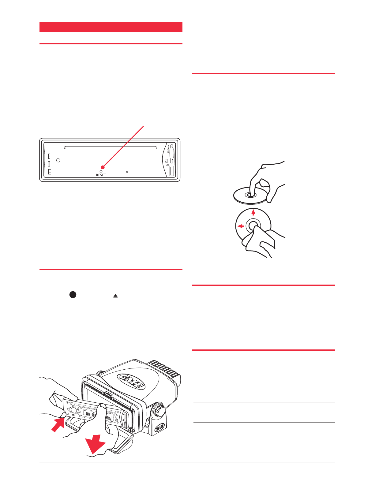
object(seePRECAUTIONSonpage5).Thiswillensure
theGR9200isreadytooperateforthersttime.Ifatany
timethecontrolsdonotseemtowork(afterreplacingthe
vessel’sbatteryforexample),presstheResetbuttontoreset
the microcomputer inside the GR9200.
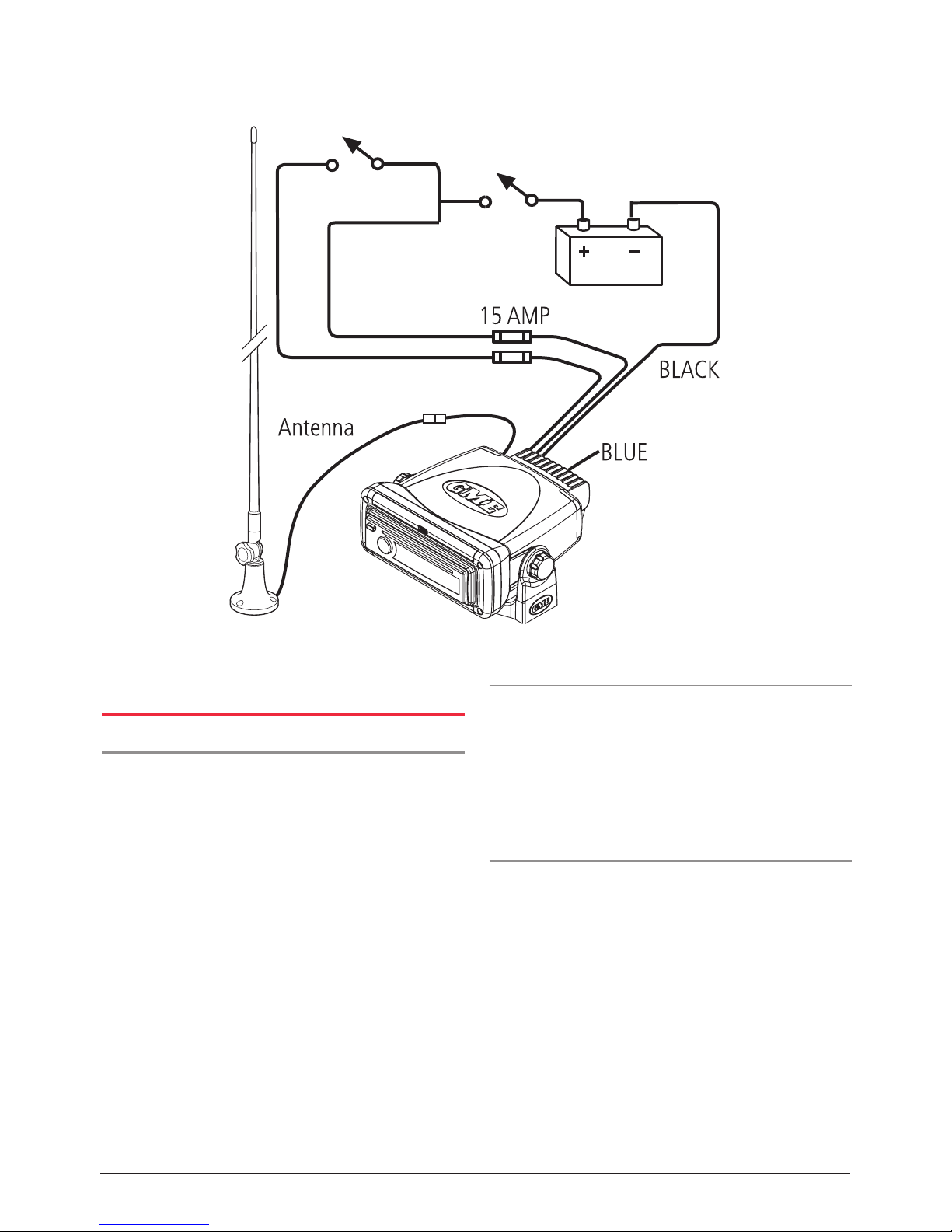
FUSE REPLACEMENT
Ifanyofthefusesblow,replacethemwithastandard
30mm3AGtypeofthesamerating.Ifthefuseblowsa
secondtimecontactyourretailer.
The following fuse ratings are used:
- Yellow‘Memory’lead:15Amp.
- Red ‘Ignition Switch ACC’ lead: 0.5 Amp.
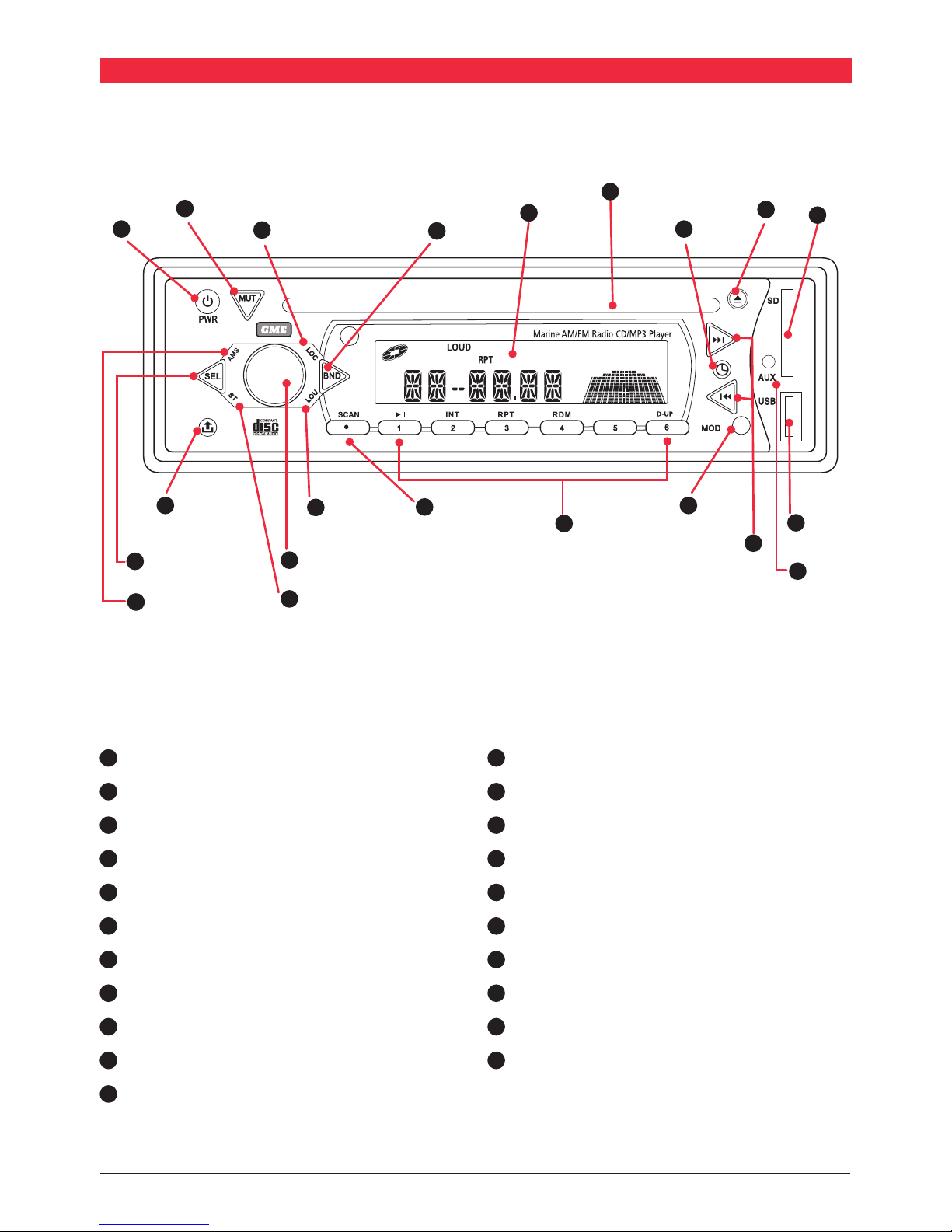
OPERATION
GENERAL FUNCTIONS
1Power ON/OFF
To turn the GR9200 ON,pressthePower Button. The unit
will resume the mode and settings that were selected when
last turned OFF.
To turn the GR9200 OFF,pressthePowerbuttonagain.
Note that when the GR9200 is turned OFF the clock is
displayedwithoutthebacklight.
Backlighting
BrieypressthePowerbuttontochangethebrightnessof
thebacklighting.Therearethreelevelsofback
lightingavailable.
23Audio Controls
TheVolume,Bass,Treble,BalanceandFadercontrolsare
selectedelectronically.Thedefaultsettingisthe
Volume Control.
Toselectanalternativecontrol,presstheSEL 3button
untilthedesiredfunctionisdisplayedontheLCD.Each
presscyclestothenextfunctioninsequence.Adjust
theselectedcontrolfunctionusingthevolumeknob 2.
4Loudness
Pressing the LOUbuttonwillprovidealowfrequency(bass
lift)boosttotheaudiooutput.Toindicatetheselection
‘LOUD’willbeilluminatedontheLCD.PressingtheLOU
buttonagainwillde-selecttheloudnessfunction.
5Mute
Pressing the MUTbuttonwilltemporarilysilencetheaudio
output.‘MUTEON’isdisplayedontheLCDtoindicatethe
GR9200hasbeenmuted.PressingtheMUTbuttonagain
willrestorethepreviouslyselectedaudiolevel.
6 Clock
Todisplaythecurrenttime,pressthe button,After2
secondsthedisplaywillreturntoit’soriginalstatus.
The time is shown in the 24 hour format.
Tosettheclock,pressandholdthe buttonuntilthe
timedisplaybeginstoash.Thetimecanthenbeadjusted
byrotatingtheVolumeknob.Toadjusthours,rotatethe
knobclockwise,toadjusttheminutes,rotateant-clockwise.
7Mode
Pressing the MODbuttonwillselecttheGR9200operating
mode.TUNER,CDorAUXmodesaresequentiallyselected
as MODispressed.IfaUSBmemorystickorSDCardis
inserted,‘USB’or‘CARD’willalsoappearinthemodelist.
When the GR9200 is switched ONitwillautomatically
return to the mode it was in when switched OFF.
8Local/Distance Control
Pressing the LOCbuttonselectsaninternalattenuator
which will help to reduce the interference and distortion
oftenassociatedwithverystronglocalradiotransmissions.
TheLOCagontheLCDisilluminatedwhentheGR9200is
in the local mode.
9Stereo/Mono Selector
Pressing the STbuttonselectseithermonoorstereo
receptionwhileinFMmode.Theunitwillmomentarily
display‘MONO’or‘STEREO’whentogglingtheST switch.
TheSTagisdisplayedwhentheGR9200isinthe
stereo mode.
Selecting MONO improves reception when FM signals are
weakornoisybydisablingstereodetection.
SelectSTEREOfornormallisteningonFMradiobands,a
symbolisdisplayedwhenstereosignalsare
beingreceived.
RADIO OPERATION
Country Selection
Whenpowerisrstapplied,theGR9200willdefaulttothe
Europeanfrequencybands.TotogglebetweenEuropean
andUSAbandsets:
1.Pressandholdthememory‘3’keyANDpressthe
powerkey.
2.Theradiowilldisplay‘Goodbye’andswitchoff.
3.SwitchtheradioONagainusingthepowerkey.USA
orEuropewillbemomentarilydisplayedtoindicatethe
selectedband.

GR9200 SERIES INSTRUCTION MANUAL PAGE 11
NOTE:IfallpowerisdisconnectedfromtheGR9200,
theunitdefaultstoEuropeanfrequencybands
when reconnected.
NOTE:Thedifferencesbetweenbandsislistedinthe
specifications at the rear of the manual.
10 Band Selector
Toselecttherequiredradioband(AM1,AM2FM1FM2or
FM3),sequentiallypresstheBNDbuttonuntiltherequired
bandisselected.
11 Tuning/Selecting Tracks
Manual Tuning
Totunetheradiomanually,momentarilypressthe or
buttontoselectthedesiredfrequency.Press to tune
up or to tune down.
Automatic Tuning (Seek)
Press and hold either the or buttonsfor1second.
TheGR9200willstopseekingwhenastrong,clearstation
is detected.
Storing of Stations in Memory
Oncethedesiredstationhasbeenselected,pressandhold
oneofthesixpresetstationmemorybuttonsonthefront
panelfor1second.Thecorrespondingbuttonnumberwill
appear on the LCD indicating that the selected station is
nowprogrammedintotheGR9200memory.
13
Auto Programming of Radio Stations (AMS)
Select the required band
Press and hold the AMSbuttonfor1second.TheGR9200
willcommencesearchingthebandforradiostations.As
eachstationislocateditisautomaticallystoredinthenext
availablepresetmemorylocation.Thenewstationswill
replaceanystationspreviouslystoredinthatband.
14 Scan
IntheTUNERmode,pressandholdtheSCANbuttonfor
1second.TheGR9200willscantheselectedradioband
forallavailablestations,pausingbrieyateachtoletyou
decidewhetheryouwishtolistentothisparticularstation.
ToexittheScanmode,presstheSCANbuttonagain.
Manually Selecting the Preset Station Memories
Brieypressthedesiredstationmemory1- 6. The GR9200
willjumpimmediatelytothatstationandthememory
numberwillappearontheLCD.
CD/MP3 OPERATION
Warning: DonotinsertCDscontaininganythingother
than standard audio or MP3 files into the disc slot. The
CD mechanism contains precision laser components which
couldeasilybedamagedbyinsertingforeignobjects.
Important:Becauseofthewidedynamicrangeoffered
byCDsystems,thedifferenceinvolumelevelbetweenvery
softsoundsandveryloudsoundscanbequitehigh.Forthis
reasonwerecommendthatyouavoidturningthevolume
leveluptooloudwhenlisteningtoverysoftmusicortracks
withnoaudiolevelotherwiseasuddenchangetoveryloud
musiccoulddamageyourspeakers.
Inserting the CD
RemovetheCDfromit’scaseandinsertthedisclabel-up
into the front panel aperture. The CD mechanism will
automaticallydrawthediscintotheplayerandstart
playingtrack1.
12 Ejecting a CD
Press the EJECTbutton tostoptheCDplayingand
automaticallyejectthedisc.
11 Fast Forward/Reverse
Toadvancethroughthepresenttrackathighspeed,press
and hold the button.Theelapsedplayingtimewillbe
displayedandwilladvancerapidly.Releasethebuttonto
continueplayingatthenormalspeed.
Toreversethroughthepresenttrackathighspeed,press
and hold the button.Theelapsedtimeonthedisplay
willdecreaserapidly.Releasethebuttontocontinueplaying
the present track at the normal speed.
GR9200
4x45
Watts
D-DN
labelsideup
Adiscsymbol isdisplayedontheLCDwhenever
thereisaCDintheplayer.Thesymbolwillsimulate
rotationwheneverthediscisplaying.

PAGE 12 INSTRUCTION MANUAL GR9200 SERIES
11 Step to the Next Track
Tostepimmediatelytothenexttrack,pressthe button
once.Thenextselectedtrackwillbeginplaying,pressthe
buttontoadvancetothestartofsuccessivetracks.
Tostepimmediatelytothestartofthetrackcurrentlybeing
played,pressthe buttononce.Thecurrenttrackwill
immediatelyrestart.Pressthe buttonrepeatedlyto
locate the start of previous tracks.
11 Pause
TopausetheCD,pressthe buttononce.Thedisc
symbolontheLCDwillstoprotatingwhenthepause
functionhasbeenselected.
Press the buttonagaintoresumeplayingtheCD.
Intro-Scan
Theintro-scanfeatureplaystherst10secondsofeach
trackallowingyoutoidentifythesongsontheCD.
To select intro-scan press the INTbutton,theLCDwill
displayINT,tracknumberandelapsedtime.
Press the INTbuttonagaintoreturntothenormalmode.
Repeat Play
Tocontinuallyrepeatthecurrenttrack,presstheRPT
button.A‘RPT’agwillbeilluminatedontheLCDwhenin
the repeat mode.
Press the RPTbuttonagaintoreturntothenormalmode.
Random Play
ToplaytracksontheCDinarandomorder,presstheRDM
button.A‘RDM’agwillbeilluminatedontheLCDwhen
in the random mode.
Press the RDMbuttonagaintoreturntothenormalmode.
MP3 Functions
MP3(MPEG-1Layer3)isaformatforthecompressionof
audiolestoapproximately8%oftheiroriginalsize.This
permitsalargenumberoflestobestoredonaCD-R,
CD-RW,SDCardorUSBmemorystick.
MP3 Music Search - To search for a particular MP3
musictrack,presstheAMSbuttononce,theLCDwill
display‘TRK .Thelefthanddigitwillbeashing.
Rotate the volume control to select the value of the first
digit then press AMS to advance to the next digit. Repeat
untiltherequiredtracknumberisdisplayed.PressSEL to
jumptothattrack.
Precautions for CD-R and CD-RW Discs
TheGR9200willnotplayaCDthathasnotbeennalised.
Please refer to the instruction manual of the software or the
recorderyouareusingtowriteyourCDsforthe
finalisation process.
Toensureamorereliableplayback,
• WriteCD-RsandCD-RWsatspeedsslowerthantheir
maximum rating.
• AvoidusingCD-RWsthathavebeenwrittenmorethan
5 times.
Note:IfadisccontainsaudioCDdataandMP3les,the
GR9200willonlyplaywhicheverisrstonthedisc.Ifthe
rsttrackonthediscisanMP3le,theunitwillonlyplay
theMP3lesfromthedisc,andwillignoreallotherles
and vice versa.
Precautions for MP3s
TheformatofthediscmustbeISO9660level1or2,or
Joliet or Romeo in the expansion format.
WhennaminganMP3le,ensuretheleextensionis‘.MP3’
The
GR9200 will not recognise a non MP3 file even if the
name extension is ‘.MP3
’
Configuration Menu
Press and hold the SELkeytoenterthecongurationmenu
thenbrieypresstheSELkeytocyclethroughtheavailable
congurationoptions.RotatetheVolumeknobtochange
the selected option. Press BNDtoexitthemenuorsimply
wait a few seconds for it to time-out.

GR9200 SERIES INSTRUCTION MANUAL PAGE 13
Function Options Description
Beep On I Off Enables/disablesconrmationbeepson
keypresses
Audio Response User Set I Flat I Classic I Rock I Pop Selects preset audio responses for various
musicstyles.Select‘UserSet’ifyouprefer
tomanuallyadjusttheaudioresponse
usingtheBass/Treblecontrols.
Volume Last I Default Set the volume level used when the radio
is turned on. Select ‘ Last ’ to restore the
volume to the last used setting.
Select Default to restore the volume to a
present default setting.
AVOL Min | 01-46 | Max Sets the preset volume setting for the
‘Default’optionabove.
iPod Baud Rate
(BPS)
38400 | 9600 Sets the Baud Rate for communicating with
iPoddevices.Thedefaultis38400bps.
IfyourolderiPoddoesn’tworkwiththe
GR9200tryselecting9600bps.
Clock On | Off Enables/disablestheclockonthedisplay
when the GR9200 is switched off.
Clock format 24 | 12 Selects12houror24hourclockdisplay.
CONFIGURATION MENU TABLE

PAGE 14 INSTRUCTION MANUAL GR9200 SERIES
AUXILIARY INPUTS & OUTPUTS
Tomaximisetheowner’slisteningexibilityandpleasure
theGR9200serieshaveseveralauxiliaryinputs
and outputs.
FRONT PANEL INPUTS
There are standard USB and SD Card inputs located on the
front panel.
USB
TheUSBInputacceptsUSBashmemorydrivesloaded
with MP3 files. When using the USB input we recommend
using the USB adapter AD003 supplied as a standard
accessorywithyourGR9200.Thisallowsthetransparent
frontcovertobefullyclosedtoavoidanypossibilityof
water ingress.
WhentheUSBinputisinuse,‘USB’isaddedtotheoptions
ontheMODbutton.
Note:TheUSBinputisnotdesignedtobeconnected
totheUSBportofaexternalMP3player.ExternalMP3
playersshouldbeconnectedtotheAUXinputviaanaudio
interfacecable.
SD Card
TheSDcardslotacceptsSDandSDHCmemorycardsupto
4GBinsizecontainingupto5000songs.
WhentheSDcardslotisinuse,‘CARD’isaddedtothe
optionsontheMODbutton.
Aux Input
TheGR9200hasa2.5mmstereojacklowlevel(1Volt
peaktopeak)audioinput.Ownersmayusethisinputfor
externalaudiosourcesthattheywishtoplaythroughthe
vessel’sstereosystem.
GMEoffersaninterfacecable(LE68)forconnecting
MP3portabledevices.Whenusingthisconnection,itis
necessarytousetheportabledevicefunctionsto
controlplay.
TousetheAUXinput,presstheMODbuttonuntil‘AUX’
isdisplayed.
CONNECTING AN iPod*
TheGR9200canbeconnecteddirectlytoaniPodviathe
optional LE023 iPod interface lead. The interface lead
connectstotheiPodyleadattherearoftheGR9200and
provides a direct connection to the interface socket on the
iPod.ThecableiscompatiblewiththecurrentiPodNano,
Classic,TouchandiPhonemodels.
WhenaniPodisconnectedtheGR9200displaysIPOD.
AlbumandsongselectionscanbemadefromtheGR9200
ordirectlyfromtheiPoditself.Anyselectionswillbe
displayedontheiPodscreen.
To make individual selections from the GR9200 controls
press the AMSbutton.‘Menu’isdisplayedontheGR9200.
Duringthistime,presstheAMS buttontostepback
throughtheiPodscreenmenus,rotatethe Volume control
to highlight items on the iPod screen and press BND
to make a selection. To exit the GR9200’s iPod ‘Menu’
function press SEL or wait a few seconds and the menu will
time-out. Normal AMS, Volume and BND functions
will resume.
To select another song press or to step forward or
backthroughthesonglist.
ToselectanotherAlbumpressD-UP or D-DN to step
forwardorbackthroughtheAlbumlist.
TheiPodbatterywillbechargedwhileitisconnectedto
the GR9200.
REAR OUTPUT
TheGR9200serieshasfrontandrear,rightandleft
channel,lowlevelaudiooutputlines.Ownersmay
usetheseoutputstodriveexternalboosterampliers
shouldtheyhaveaparticularlylargevesselorrequire
supplementaryaudiooutputpower.
Whenasuitableexternalamplierisconnectedthevolume,
toneandbalancesettingsmaystillbecontrolledattheGR9200.
Warning:Extremecareshouldbetakenwhenconnecting
anyexternaldevicetoyourGR9200rearinputsoroutputs.
GMEstronglyrecommendsthatallsuchinstallationsshould
becarriedoutbyasuitablyqualiedtechnician.

GR9200 SERIES INSTRUCTION MANUAL PAGE 15
ThereareanumberofhighqualityGMEaccessories
availabletoenhanceyourmarineentertainmentexperience.
TheseaccessoriesareavailablethroughyourlocalGME
retailer,shouldyouhaveanydifcultyinobtainingany
GMEaccessory,pleasecalloremailyourlocalGMESales
Ofce(withinAustraliaandNewZealand).Contactdetails
arelistedonthebackpageofthismanual.
Internationalcustomersshouldalsorefertothebackpage
fordetailsofyourlocalimporterorvisit:
www.gme.net.au
•Marine Speakers
•Comprehensive Range of Marine Antennas
• InterfacecableforMP3devices
•RCU9200 - Wired Remote Control for Stereo
• LE024-WiredRemote5mExtensionCable
• LE023-iPod*ConnectivityLead1.1mLong
*iPodisatrademarkofAppleComputerInc.,registeredintheU.S.
and other countries.
FromtimetotimeGMEmayintroducenewandadditional
products to the range or discontinue existing accessories.
Detailsofanychangesmaybefoundatourwebsite:
www.gme.net.au
SPK005andSPK006boxspeakers
SPK008wakeboardspeaker
andSPK010marinesubwoofer
OPTIONAL ACCESSORIES
AM/FM Antennas
SPK0076x9speaker RCU9200 wired remote LE68AUXinputcable
LE023iPodinterfacecable LE024RCUInterfacecable(5m)
GA9800 - GME Marine Amplifier
SPK001andSPK002speakers

PAGE 16 INSTRUCTION MANUAL GR9200 SERIES
GR9200 TROUBLE SHOOTING GUIDE
SYMPTOM CAUSE SOLUTION
No Power. Vessel’sbatteryswitchisnoton. Check master switch if fitted.
Oneofthefusesisblown. Replace the damaged fuse with the
correct value.
ErrormessagesdisplayedonLCDor
functions not operating.
Microprocessor lock up. Press Reset Button.
Poor radio reception. Damagedorincorrecttypeofantenna. Check antenna and replace
ifnecessary.
CDcannotbeloaded. ThereisalreadyaCDintheplayer. Removedisc,theninsertnewCD.
CD is upside down. Insertcorrectwayup.
CDisdamagedordirty. Cleanortryanotherdisc.
CD has moisture on it. Drydiscandretry.
CD reader has moisture on lens. Leaveplayeronforanhourorso
andretry.

GR9200 SERIES INSTRUCTION MANUAL PAGE 17
FM RADIO
FrequencyRange: 87.5-108MHz(Eu./Aust./N.Z.)
87.5-107.9MHz(U.S.A.)
FrequencyStep: 50kHz(Eu./Aust./NZ
200kHz/USA
IntermediateFrequency: 10.7MHz
Sensitivity(30dBS/N): 13dBuV(typical)
Channel Separation: 32 dB
Station Memories: 18
AM RADIO
FrequencyRange: 522-1620MHz(Eu./Aust./N.Z.)
530-1710MHz(U.S.A.)
FrequencyStep: 9kHz(Eu./Aust./N.Z.)
10kHz(U.S.A.)
IntermediateFrequency: 450kHz
Sensitivity(20dBS/N): 17dBuV
Station Memories: 12
COMPACT DISC MECHANISM
Mechanism: Auto Loading
Signal to Noise Ratio: 58 dB
Format: 8 times oversampling
Environmental: Anti-vibration/Anti-shock
AUDIO AMPLIFIER
AudioOutput: (4channelsx45WPeak=
180WPeak)@10%THD.
Speaker Impedance: 4 Ohm
BassAdjustmentRange: +/-10dB
TrebleAdjustment
Range: +/- 12 dB
GENERAL
DCSupplyInput: 10–16VoltsNegativeGround
MemoryBack-up: ExternalBack-upMemoryWire
Back-upCurrent: Approximately16mA
OverallSize: 232mm(W)x97mm(H)x
200mm(D)excludingheat
dissipator.
Weight: 1.55kg-GR9220,
2.6 kg - GR9240.
SupplyCurrent: 7Amps(max.)
SPECIFICATIONS*
*All specifications are typical and subject to change without notice or obligation.

PAGE 18 INSTRUCTION MANUAL GR9200 SERIES
STANDARD COMMUNICATIONS CONTRACT WARRANTY
1. STATUTORY WARRANTIES
1.1 TheTradePracticesActPartV,Division2Aandotherlegislation
implyconditions,warrantiesandotherobligationsonusto
consumersthatcannotbeexcluded,restrictedormodified.
Thoseprovisionsapplytotheextentrequiredbylaw.
1.2 Weexcludeallotherconditions,warrantiesandobligations
whichwouldotherwisebeimpliedconcerningtheactivities
coveredbythisagreement.
1.3 Welimitourliabilitywhereweareallowedtodoso.Examples
ofwhereweareallowedtolimitliabilityare-
(a)youacquiregoodsfromusforre-supply;
(b)thegoodsorserviceswesupplyarenotofakindordinarily
acquiredforpersonal,domesticorhouseholduse
or consumption.
1.4 Whereweareallowedtolimitourliability,totheextent
permittedbylaw,oursoleliabilityforbreachofacondition,
warrantyorotherobligationimpliedbylawislimited-
(a) inthecaseofgoodswesupply,toanyoneofthefollowing
as we decide -
(i) thereplacementofthegoodsorthesupplyof
equivalentgoods;
(ii) therepairofthegoods;
(iii) thepaymentofthecostofrepairingthegoodsorof
acquiringequivalentgoods;
(iv) thepaymentofthecostofhavingthegoods
repaired;or
(b)inthecaseofserviceswesupply,toanyoneofthe
following as we decide -
(i) thesupplyingoftheservicesagain;
(ii) thepaymentofthecostofhavingtheservices
supplied again.
2. ADDITIONAL WARRANTIES
2.1 Thewarrantiesinthisclauseareinadditiontothestatutory
warranties referred to in the previous clause.
2.2 Wewarrantourgoodstobefreefromdefectsinmaterials
andworkmanshipforoneyearfromthedateoforiginal
sale(oranotherperiodweagreetoinwriting).Duringthis
periodandasoursoleliabilitytoyouunderthiswarranty,
weagreeto,atouroption,eitherrepairorreplacegoods
which we are satisfied are defective. We warrant
replacement parts for the remainder of the period
ofwarrantyforthegoodsintowhichthey
are incorporated.
2.3 Wewarrantourotherrepairstobefreefromdefectsin
materials and workmanship for three months from the
date of the original repair. During this period and as
oursoleliabilitytoyoufortherepair,weagreeto
repairorreplace(atouroption)repairedgoodswhich
we are satisfied are defective.
2.4 We warrant that we will perform services with
reasonablecareandskillandagreetoinvestigate
anycomplaintmadeingoodfaiththatwehave
performedservicesunsatisfactorily.Ifwearesatisfied
thatthecomplaintisjustified,andasoursoleliability
toyouunderthiswarranty,weagreetosupplythose
servicesagainatnoextrachargetoyou.
2.5 Ifyouwantwarrantyserviceunderthisclauseyou
mustgiveusanoriginalorcopyofthesalesinvoice
from the transaction or some other evidence showing
details of the transaction.
3. OTHER LIMITATIONS
3.1 Youmaynotrelyonanyrepresentation,warrantyor
otherprovisionbyorforuswhichisnotcoveredby
clause [ 1 ] or repeated in this agreement in
clear terms.
3.2 Wearenotliable(norareouremployees,contractors
andagents)foranydamage,economiclossor
lossofprofitswhetherdirect,indirect,general,special
or consequential -
(a) arisingoutofanybreachofanyimpliedor
expressterm,conditionorwarranty;or
(b) sufferedasaresultofournegligence(orthat
ofouremployees,contractorsoragents)
- apartfromliabilityassetoutintheprevious
two clauses.
3.3 Theliabilityofapartyunderthisagreement(whether
arisingincontract,tortorbystatute)istobereduced
bythesameproportionasrepresentstheproportion
ofthelossordamagecausedorcontributedtobythe
otherparty,itscontractorsoragents.
GME AFTER SALES SERVICE
YourGMEGR9200isespeciallydesignedfortheenvironment
encounteredinmobileorportableapplications.Theuseofall
solidstatecircuitry,carefuldesignandrigoroustesting,resultin
highreliability.Shouldfailureoccurhowever,GMEmaintaina
fullyequippedservicefacilityandsparepartsstocktomeetthe
customer’srequirementslongafterexpiryofthewarrantyperiod.

GR9200 SERIES INSTRUCTION MANUAL PAGE 19

A Division of
Head Office: SYDNEY
-LockedBag2086,NorthRyde,NSW1670,Australia.Tel:+61(0)298446666Fax:+61(0)298446600
MELBOURNE ADELAIDE PERTH BRISBANE SYDNEY AUCKLAND
7 Micro Circuit Unit 1 Unit 1 Unit 1 Unit B 2/24 Bishop Dunn Place
DANDENONGSTH3165 14PhillipsStreet 10-12HarvardWay 89-101FactoryRoad 22-24CollegeStreet EastTamaki
Tel:(03)97980988 THEBARTON5031 CANNINGVALE6155 OXLEY4075 GLADESVILLE2111 MANUKAU2013NZ
Fax:(03)97980177 Tel:(08)82342633 Tel:(08)94555744 Tel:(07)32786444 Tel:(02)98798888 Tel:(09)2740955
Fax:(08)82345138 Fax:(08)94553110 Fax:(07)32786555 Fax:(02)98164722 Fax:(09)2740959
ForcustomersoutsideAustraliaandNewZealandpleasecontactyourlocalGMEDistributororemail:[email protected]
Web Site: www.gme.net.au
Part No:
310443
Drawing No:
44415-1 INSTRUCTION MANUAL GR9200 SERIES
This manual suits for next models
3
Table of contents
Other GME Marine Audio manuals
Popular Marine Audio manuals by other brands

Garmin
Garmin Fusion MS-RA60 installation instructions

Dual
Dual DMS6516 Installation & owner's manual

Sony
Sony CDXM60UI - Marine CD Receiver MP3/WMA/AAC... operating instructions

Sony
Sony XS-HF137 Installation/connections

Clarion
Clarion CM1624TB Owner's manual & installation manual

Altec Lansing
Altec Lansing 55-4A SPEAKER SYSTEM manual