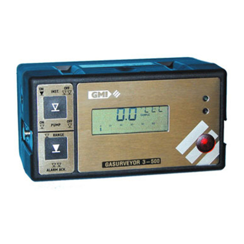
GMI Gasurveyor 500 Series Instruction Manual

GASURVEYOR 500 USER HANDBOOK
Issue
/0/1
Part Number: 42153
GMI welcomes comments on all our publications.
Your comments can be of great value in helping us
to improve our customer publications. Please send
any comments that you have to our Sales
Department at GMI. Contact details are provided
inside the back cover of this handbook.
Instrument Service / Repair contact details are also
provided inside the back cover of this handbook.
Copyright ©Gas Measurement Instruments Ltd 2000

i
COPYRIGHT
COPYRIGHT
ThisUserHandbookiscopyrightofGasMeasurementInstrumentsLtd(GMI)and
theinformation contained within is for use onlywith the Gasurveyor 500 series of
instruments. Reproduction, in whole or in part, including utilisation in machines
capableofreproductionorretrievalwithoutwritten permission ofGasMeasurement
InstrumentsLtd is prohibited. Reverse engineering isnotpermitted.
LIABILITY
Everycarehasbeentakeninthepreparationofthisdocument, but GMI Ltd do not
acceptany responsibilityforerrorsoromissionsandtheirconsequences. Information
inthisdocumentissubjecttochangewithoutnotice.Thisdocumentdoesnotconstitute
aspecification orbasisfor acontract.Yourstatutoryrightsunder lawarenotaffected.
MODIFICATION NOTICES
GMIaimtonotifycustomersofrelevantchangesintheproductoperation andmaintain
thismanual uptodate. Inviewofthe policyofcontinuous productimprovementthere
maybeoperationaldifferencesbetweenthelatestproduct and this manual.
ThisHandbookis an importantpartoftheGasurveyor 500 product. Pleasenotethe
followingpoints:
• Itshouldbekept with the instrument for the life of theproduct.
• Amendmentsshould beattached.
• ThisHandbookshouldbepassedon to any subsequent owner/user of the
instrument.
• Althougheverycareistaken in the preparation of this Handbook it does not
constituteaspecification for the instrument.
SOFTWARE
SoftwaresuppliedonEPROM or similar device for use in a particular product,may
onlybe used inthatproductand may notbecopiedwithout thewrittenpermissionof
GasMeasurement InstrumentsLtd.Reproduction ordisassemblyofsuch embodied
programmes or algorithms is prohibited. Ownership of such software is not
transferableandGMI Ltd does not warrant thattheoperationofthesoftware will be
errorfree or that the softwarewill meet the customer’s requirements.
DISPOSAL ADVICE
Whennolongerinuse,disposeoftheinstrument carefully and with respect for the
environment.GMI will dispose of theinstrument without charge if returnedto the
factory.

GASURVEYOR 500 USER HANDBOOK
ii
SAFETY
• Theinstrumentmust be regularly serviced and calibratedbyfullytrained
personnelina safe area.
•Batteries: Alkalinebatteriesor*Rechargeablebattery pack must be exchanged
(*andrecharged) in a safearea and fitted correctly beforeuse.
Neverusedamagedbatteries or expose to extreme heat.
SeeSection 4 : OPERATORMAINTENANCE.
• OnlyGMIreplacementparts should be used.
• Iftheinstrument detects gas, follow your own organisation’sproceduresand
operationalguidelines.
• Thecombustionchamberisaflameproofassemblyandmustnotbe opened in
thepresenceofaflammable atmosphere.
• Gasurveyor500 series instruments are certifiedasEEx iad IIC T4
(-20oC<Tamb <50oC).BAS01ATEX2292 II2G.
UL Class 1 Groups A, B, C and D
• This equipment is designed and manufactured to protect against other hazards
asdefinedin paragraph1.2.7 ofAnnex II of theATEXDirective94/9/EC.
Anyrightofclaim relating to product liability or consequential damage toanythirdparty
againstGMI is removed if thewarningsare not observed.
AREAS OF USE
Exposuretocertainchemicalscanresultinalossofsensitivityoftheflammablesensor.
Wheresuch environments areknownorsuspected it isrecommendedthatmore frequent
response checks are carried out. The chemical compounds that can cause loss of
sensitivity include Silicones, Lead, Halogens and Sulphur. Do not use instrument in
potentiallyhazardousatmospheres containing greater than21%Oxygen.Theenclosure
materialispolypropylene and must not be exposed to environmentswhichare liable to
result in mechanical or thermal degradation or to damage caused by contact with
aggressivesubstances. Additional protectionmayberequiredin environments wherethe
instrumentenclosure is liable to damage.
STORAGE, HANDLING AND TRANSIT
Thebatteriesintherechargeablepackcontainconsiderableenergyandcareshouldbe
takenintheir handling anddisposal.Batterypacksshould be removed iftheinstrumentis
storedfor longerthan3 months.Theinstrument isdesignedto handleharshenvironments.
The sensing elements are sealed to IP54 and the rest of the instrument to IP64. If not
subjectto misuse or maliciousdamage,theinstrumentwill provide manyyearsofreliable
service.The instrument contains electrochemical sensorswith a life of 2years. Under
conditionsof prolonged storage the sensorsshould be removed. The sensorcontains
potentiallycorrosive liquid and care should be takenwhenhandling or disposing of the
sensor,particularlywhena leak is suspected.

iii
DECLARATION OF CONFORMITY
Refer to current
Declaration of Conformit
y
document Part No. 4290
7
(supplied with product)

GASURVEYOR 500 USER HANDBOOK
iv

v
REVISION RECORD
Date Issue Description Of Change
18/08/00 1 New Handbook
09/05/01 2 Revised to reflect generic
instrument options and
features
06/01/03 3 Revised to include Geiger
clarification and effect of
CN 2313
17/07/03 4 Revised to include effect
of CN 2291
26/07/04 5 Revised to include
Appendix C (translations)
08/06/07 6 Revised to include Marine
Equipment Directive (MED),
Declaration of Conformity
and effect of CN 4092,
CN4202 and CN4338.
05/06/13 7 Revised to include effect
of CN 5017 and CN 6257.
24/09/15 8 Revised to include effect
of CN 6519.

GASURVEYOR 500 USER HANDBOOK
vi

vii
CONTENTS
COPYRIGHT ................................................................... i
LIABILITY ....................................................................... i
MODIFICATIONNOTICES ................................................ i
SOFTWARE ................................................................... i
DISPOSALADVICE ........................................................ i
SAFETY .........................................................................ii
AREASOFUSE ............................................................. ii
STORAGE,HANDLINGANDTRANSIT ..........................ii
DECLARATIONOFCONFORMITY.................iii
REVISIONRECORD .......................................v
INTRODUCTION .......................................... 1-1
GENERALINFORMATION .......................... 2-1
Ranges of Operation .................................................2-1
LEL, 0 to 100%........................................................2-1
Volume Gas, 0 to 100 % .........................................2-2
ppmFlammable 0– 1000ppm.................................2-2
Threshold Display Options......................................2-4

GASURVEYOR 500 USER HANDBOOK
viii
Oxygen, 0 – 25% ....................................................2-4
Toxic Ranges ..........................................................2-5
Alarms........................................................................2-5
Alarm Functions ......................................................2-6
Geiger Indication .....................................................2-7
Datalogging ................................................................2-7
CSMMode ...............................................................2-8
CGIMode .................................................................2-8
Construction ..............................................................2-8
Batteries.....................................................................2-9
Disposable Alkaline (LR20) Dry Cell Batteries........2-9
Rechargeable (NiCd) Battery Pack.........................2-9
Filters .......................................................................2-10
Liquid Crystal Display (LCD) ...................................2-10
Before Use Checks .................................................2-10
OPERATINGINSTRUCTIONS ..................... 3-1
Operating Modes .......................................................3-1
Confined Space Monitor (CSM) Operation ................3-2
Switching On in CSM Mode ....................................3-2
Calibration Date Features .......................................3-4
Switching Off..........................................................3-4
Changing Gas Range ..............................................3-4
Datalogging (Default) ..............................................3-5
Cycling Through the Display Options .....................3-5

ix
CONTENTS
ClearingAlarms .......................................................3-6
Notes on (default) CSM mode:................................3-7
Summary of (default) CSM Button Operation.........3-7
Combustible Gas Indicator (CGI) Operation ..............3-8
Switching On in CGI Mode ......................................3-8
Calibration Date Features .......................................3-9
Switching Off the Instrument Pump........................3-9
Switching Off..........................................................3-9
ChangingRange....................................................3-10
Activate the Audible Geiger Indication
(PPMrange) ..........................................................3-10
Zeroingthe PPMRange ........................................3-10
Manual Datalogging (Default)................................ 3-11
Summary of CGI Button Operation ....................... 3-11
Operator Messages / Fault Flags............................3-12
OPERATORMAINTENANCE ...................... 4-1
Rechargeable Battery Pack.......................................4-1
Standard Charger....................................................4-1
Flatbed Charger ......................................................4-2
Smart Charger.........................................................4-2
Replacing the Battery Pack.....................................4-3
Recharging the Battery Pack ..................................4-4
ReplacingAlkaline (LR20) Dry Cell Batteries ............4-4
FilterReplacement .....................................................4-5

GASURVEYOR 500 USER HANDBOOK
x
CALIBRATION ............................................. 5-1
Calibration Validity......................................................5-2
ACCESSORIES .......................................... 6-1
ADDITIONALINFORMATION....................... 7-1
Training ......................................................................7-1
World Wide Web ........................................................7-1
TYPICALOPERATINGPARAMETERS .......A-1
Size ........................................................................ A-2
Weight .................................................................... A-2
Operating Temperature .......................................... A-2
Humidity .................................................................. A-2
Construction........................................................... A-2
Display.................................................................... A-2
SamplingSystem.................................................... A-2
Response Time (O2) .............................................. A-2
Power Source........................................................ A-3
FIELDCALIBRATION ..................................B-1
Selectable Ranges in FCM........................................ B-3
EnteringFCM............................................................. B-3

xi
CONTENTS
Zeroing the Instrument ............................................. B-4
Field Calibration Procedure....................................... B-5
EditCal DueDate ...................................................... B-8
Quit And Save Changes ........................................ B-9
Quit Without Saving Changes ................................ B-9
QUICKOPERATINGINSTRUCTIONS..........C-1
English....................................................................... C-2
L'italiano(Italian) ....................................................... C-6
Español (Spanish)................................................... C-10
Svensk (Swedish) ................................................. C-14
Dansk (Danish) ....................................................... C-18
Nederlands (Dutch) ................................................ C-22
INDEX ............................................................. I

GASURVEYOR 500 USER HANDBOOK
xii

1-1
INTRODUCTION
INTRODUCTION
The Gasurveyor 500 is a highly flexible, portable gas
detector which can be configured from a simple single
gas instrument, through to a sophisticated four gas multi-
tasking instrument. The instrument is designed to the latest
standards and is certified for use in Hazardous Areas.
Figure 1-1 Gasurveyor 500 series Instrument
The Gasurveyor 500 can contain up to six gas ranges
with the following ranges being possible:
• LEL, 0 to 100%
• Volume gas, 0 to 100%
• PPMFlammable
• Oxygen, 0 to 25%
• Toxic range 1
• Toxic range 2
1

GASURVEYOR 500 USER HANDBOOK
1-2
This handbook covers all possible measurement ranges
and for illustration purposes refers to the instrument as
a Gasurveyor 500. The instrument that this manual has
been supplied with is part of the Gasurveyor 500 series,
e.g. Gasurveyor 521: LEL/Vol ; Oxygen.
Gasurveyor 531: LEL/Vol ; Oxygen ; Hydrogen
Sulphide.
Gasurveyor 536: PPM ; LEL/Vol ; Carbon Monoxide
; Hydrogen Sulphide, etc.
As the Gasurveyor 500 series has a wide variety of
available user selected options, it would not be possible to
provide an operator handbook specific to each possible
variation, therefore, what we have provided in the following
pages is the standard default of how the instrument would
generally be configured, with the possible options detailed
in italic text.
GMI recommend that you take the time to study your
instrument and, where practical and with advice from your
company’s Purchasing / Management departments,
highlight your particular instrument configuration.
The main default features of the instrument are:
• Rugged polypropylene case, sealed to IP54 rating
and suitable for outdoor use.
• Four button operation allowing the user access to
all features.
• Two operating modes: Confined Space Monitor
(CSM) mode and Combustible Gas Indicator (CGI)
mode .
• LCD with backlighting which displays the current
gas readings (in both digital and analogue forms)
together with operational and status information.

1-3
INTRODUCTION
• Audible and Visual alarms. Alarm levels are
pre-set and when on, a periodic confidence signal
is emitted. The confidence audible and confidence
visual signals will provide assurance that the
instrument is sensing for gas without the need for
the operator to constantly view the display. The
signals, which consist of an audible ‘beep’ and a
visual pulse of the LED approximately every eight
seconds, are active in CSM mode and also active
in CGI mode (but for the PPM Flammable range
only).
• Audible and Visual Geiger indication, enabled in
the PPM Flammable range, provides indication of
gas concentration increase via the increased rate
of sounder and LED pulse.
• Manual and automatic datalogging.
• Directly interfaces with the GMI Auto Test
Calibration Systems.

GASURVEYOR 500 USER HANDBOOK
1-4

2-1
GENERAL INFORMATION
GENERAL INFORMATION
Ranges of Operation
LEL, 0 to 100%
The LEL range indicates the explosibility of the flammable
gas in the sample. This is displayed as a percentage of
the lower explosive limit (LEL) of the gas.
The instrument range is displayed in the top right corner
of the display as % LEL. From 0 to 10% LEL the digital
display resolves to 0.1% LEL. From 10 to 100% LEL the
digital display resolves to 1% LEL. The analogue bar graph
follows in 4% steps. An example of the LEL display is
shown in Figure 2-1.Autoranging will automatically switch
the range to Volume Gas when 100% LEL is reached.
The detection principle for this range is a catalytic
reaction.
Figure 2-1 LEL Range
2

GASURVEYOR 500 USER HANDBOOK
2-2
Volume Gas, 0 to 100 %
Thisrange displaysthe totalvolume ofa specificflammable
gas with respect to air. The calibration gas is shown on
the service label and for the purpose of this handbook is
assumed to be methane. Instruments calibrated for
methane in air should only be used for measuring such
mixtures. To change the calibration gas, e.g. from methane
to propane, the instrument must be recalibrated by suitably
trained personnel.
Onthe Volume Gasrange the instrumentrange isdisplayed
in the top right corner of the LCD as GAS. The digital
display resolves the signal to 1% GAS with the analogue
bar graph following in steps of 4%. Figure 2-2 shows the
Volume Gas display. The detection principle for the Volume
Gas range is thermal conductivity.
Figure 2-2 Volume Gas Range
ppm Flammable 0 – 1000 ppm
This range is used to measure very low levels of gas and
indicates the parts per million concentration of the gas in
air (1000 ppm is equivalent to 0.1% Volume Gas).
The digital display reading resolves to 5 ppm with the
analogue bargraph following in steps of 40 ppm. The ppm
range is more sensitive than LEL and Volume ranges and
takes longer to stabilise. The detection principle is a
catalytic reaction with the sensitivity of the sensors,
greatlyenhanced comparedto theLEL range.Digital signal
Other manuals for Gasurveyor 500 Series
1
This manual suits for next models
3
Table of contents
Languages:
Other GMI Gas Detector manuals

GMI
GMI GS700 User manual

GMI
GMI PPM Gasurveyor 500 Instruction Manual

GMI
GMI PS500 Instruction Manual

GMI
GMI Gasurveyor 700 User manual

GMI
GMI PS1100 Operating instructions

GMI
GMI Gasurveyor 11-500 Instruction Manual

GMI
GMI Gasurveyor 3-500 Instruction Manual

GMI
GMI OXYGAS 500 TRAINING User manual

GMI
GMI PS500 Instruction Manual

GMI
GMI Oxygas P-500 Instruction Manual