GMI D5072D-087 User manual

D5072-087 - SIL 2 Resistance Isolating Repeater G.M. International ISM0178-5
SIL 2 Resistance Isolating Repeater DIN-Rail
Models D5072S-087, D5072D-087
D5072S-087 - D5072D-087
INSTRUCTION MANUAL

2 D5072-087 - SIL 2 Resistance Isolating Repeater G.M. International ISM0178-5
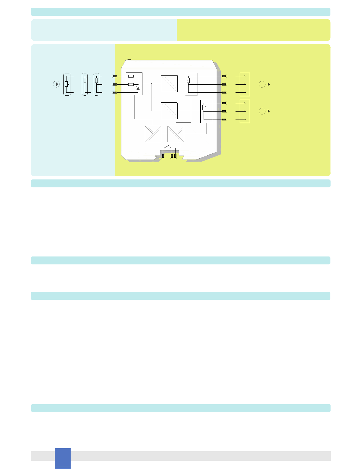
General Description:
The single and dual channel Isolating Repeater D5072S-087 and D5072D-087 accepts a resistance/RTD or transmitting potentiometer sensor, located in Hazardous Area, and repeats
the resistance, with isolation, to Safe Area, suitable for applications requiring SIL 2 level (according to IEC 61511) in safety related systems for high risk industries.
Mounting on standard DIN-Rail, with or without Power Bus, in Safe Area / Non Hazardous Location or in Zone 2 / Class I, Division 2 or Class I, Zone 2.
Fault Detection:
D5072S-087 and D5072D-087 modules are able to detect the breakage of any Input sensor line (Burnout).
Technical Data
Characteristics
Supply:
Voltage: 24 Vdc nom (18 to 30 Vdc) reverse polarity protected, ripple within voltage limits 5 Vpp, 2 A time lag fuse internally protected.
Current consumption @ 24 V: 26 mA (D5072S-087), 37 mA (D5072D-087) typical with 1 mA exitation current.
Power dissipation @ 24 V: 0.65 W (D5072S-087), 0.9 W (D5072D-087) typical with 1 mA excitation current.
Isolation:
Test voltage: I.S. In/Out 2.5 KV; I.S. In/Supply 2.5 KV; I.S. In/I.S. In 500 V; Out/Supply 500 V; Out/Out 500 V.
Input:
Type: 2-3-4 wire (4 wire only for D5072S-087) RTD/Resistance or 2-wire transmitting potentiometer.
Integration time: from 50 ms to 500 ms depending on sensor and fast/slow integration.
Resolution: 10 m.
Input range: 0 to 4 k.
Measuring RTD current: 0.15 mA.
Fault:
Type: Burnout / Internal fault. Output reflects fault condition via highscale (450 ) value forcing. Fault condition is also signaled via BUS and red LED on front panel.
Output:
Type: 2-3-4 wire (4 wire only for D5072S-087) Resistance.
Transfer characteristic: linear or custom; optional using of multiplication factor.
Response time: 10 to 90 % step: 10.0 ms (slow integration time), 1.2 ms (fast integration time).
Output range: 0 to 400 .
Excitation current (Ie): 0.1 to 10 mA.
Performance:
Ref. Conditions: 24 V supply, 23 ± 1 °C ambient temperature, slow integration mode, 4 wires (for D5072S-087) or 3 wires (for D5072D-087) configuration for RTD, input/output range
10 to 400 .
Input to output:
Calibration and linearity accuracy with input standard range:
< 200 mtypical (Excitation Current 1 mA);
< 300 mtypical (0.5 mA Excitation Current < 1 mA).
Temperature influence with input standard range:
± 20 m/°C, typical (Excitation Current 1 mA).
Compatibility:
CE mark compliant, conforms to Directives:
2014/34/EU ATEX, 2014/30/EU EMC, 2014/35/EU LVD, 2011/65/EU RoHS.
Environmental conditions:
Operating: temperature limits – 40 to + 70 °C, relative humidity 95 %, up to 55 °C.
Storage: temperature limits – 45 to + 80 °C.
Safety Description:
ATEX: II 3(1)G Ex nA [ia Ga] IIC T4 Gc, II (1)D [Ex ia Da] IIIC, I (M1) [Ex ia Ma] I
IECEx / INMETRO / NEPSI: Ex nA [ia Ga] IIC T4 Gc, [Ex ia Da] IIIC, [Ex ia Ma] I,
EAC-EX: 2Ex nA [ia Ga] IIC T4 Gc X, [Ex ia Da] IIIC, [Ex ia Ma] I.
UKR TR n. 898: 2ExnAiaIICT4 X, ExiaI X
associated apparatus and non-sparking electrical equipment.
D5072S-087: Uo/Voc = 7.2 V, Io/Isc = 23 mA, Po/Po = 40 mW,
Ui/Vmax = 12.8 V, Ci = 0 nF, Li = 0 nH at terminals 7-8-9-10.
D5072D-087: Uo/Voc = 7.2 V, Io/Isc = 16 mA, Po/Po = 27 mW,
Ui/Vmax = 12.8 V, Ci = 0 nF, Li = 0 nH at terminals 7-8-9, 10-11-12.
Um = 250 Vrms or Vdc, -40 °C Ta 70 °C.
Approvals:
BVS 12 ATEX E 053 X conforms to EN60079-0, EN60079-11, EN60079-15,
IECEx BVS 12.0050X conforms to IEC60079-0, IEC60079-11, IEC60079-15.
INMETRO DNV 13.0110 X conforms to ABNT NBR IEC60079-0, ABNT NBR IEC60079-11, ABNT NBR IEC60079-15, ABNT NBR IEC60079-26.
C-IT.MH62.B.04182 conforms to GOST R IEC 60079-0,GOST R IEC 60079-11, GOST R IEC 60079-15.
C16.0036 X conforms to 7113, 22782.5-78, I 60079-15.
GYJ14.1406X conforms to GB3836.1, GB3836.4; GB3836.8, GB3836.20.
TUV Certificate No. C-IS-236198-02, SIL 2 according to IEC 61511 for D5072S-087.
DNV Type Approval Certificate No.A-13625 and KR No.MIL20769-EL002 Certificates for maritime applications.
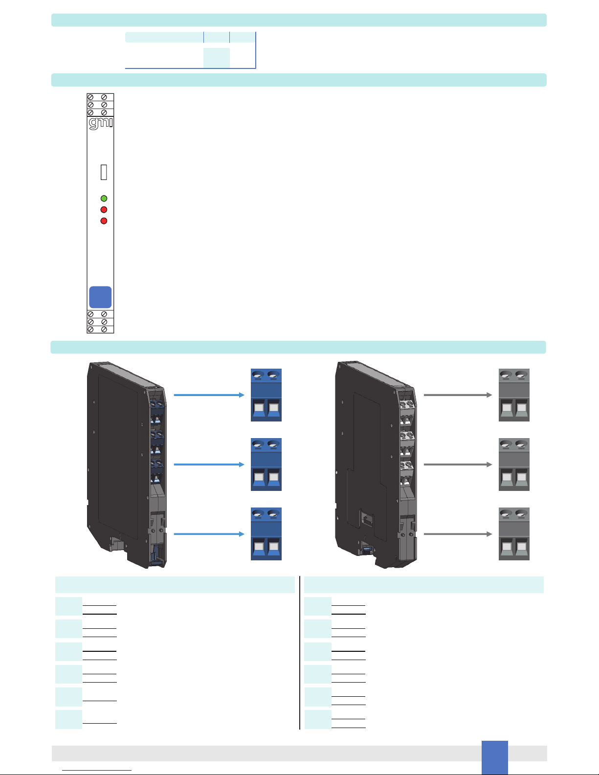
Mounting:
EN/IEC60715 TH 35 DIN-Rail, with or without Power Bus.
Weight: about 135 g D5072D-087, 130 g D5072S-087.
Connection: by polarized plug-in disconnect screw terminal blocks to accommodate terminations up to 2.5 mm2.
Location: installation in Safe Area/Non Hazardous Locations or Zone 2, Group IIC T4 or Class I, Division 2, Group A,B,C,D, T4 or Class I, Zone 2, Group IIC, T4.
Protection class: IP 20.
Dimensions: Width 12.5 mm, Depth 123 mm, Height 120 mm.
The module is fully programmable. Operating parameters can be changed from PC via PPC5092 adapter connected to USB serial line and SWC5090 software.
Measured values and diagnostic alarms can be read on both serial configuration or Modbus output line.
SWC5090 software also allows the Monitoring and Recording of values. For details please see SWC5090 manual ISM0154.
Programming

3
D5072-087 - SIL 2 Resistance Isolating RepeaterG.M. International ISM0178-5
Ordering Information
Front Panel and Features
SIL 2 according to IEC61511 for Tproof=3/10yrs (10% / >10 % of total SIF), SFF 77.64%,
PFDavg (1 year) 3.03 E-04 for D5072S-087.
Input from Zone 0 (Zone 20) / Division 1, installation in Zone 2 / Division 2.
2 or 3 or 4 wire resistance/RTD or 2 wire transmitting potentiometer Input Signal.
Burnout Fault detection.
Three port isolation, Input/Output/Supply.
EMC Compatibility to EN61000-6-2, EN61000-6-4, EN61326-1, EN61326-3-1 for safety systems.
ATEX, IECEx, INMETRO, EAC-EX, UKR TR n. 898, NEPSI, TÜV Cerifications.
Type Approval Certificate DNV and KR for maritime applications.
Simplified installation using standard DIN-Rail and plug-in terminal blocks, with or without Power Bus.
250 Vrms or Vdc (Um) max. voltage allowed to the instruments associated with the barrier.
Terminal block connections
SIL 2
5 6
2
4
1
3
7 8
12
10
11
9
D5072
-087
CONFIG
PWR
FLT 1
FLT 2
D5072S-078: Input for 3, 4 wire RTD
D5072D-078: Input Ch1 for 3 wire RTD
HAZARDOUS AREA SAFE AREA
D5072S-078: Input for 2, 3, 4 wire RTD or potentiometer
D5072D-078: Input Ch1 for 2, 3 wire RTD or potentiometer
D5072S-078: Input for 2, 3, 4 wire RTD or potentiometer
D5072D-078: Input Ch1 for 2, 3 wire RTD or potentiometer
D5072S-078: Input for 4 wire RTD
D5072D-078: Input Ch2 for 2, 3 wire RTD or potentiometer
D5072D-099: Input Ch2 for 3 wire RTD
D5072D-099: Input Ch2 for 2, 3 wire RTD or potentiometer
7
8
9
10
11
12
D5072S-087: +Output for 3, 4 wire RTD
D5072D-087: +Output Ch1 for 2, 3 wire RTD
1
D5072S-087: +Output for 2, 3, 4 wire RTD
D5072D-087: -Output Ch1 for 2, 3 wire RTD
2
D5072S-087: -Output for 2, 3, 4 wire RTD
D5072D-087: +Output Ch2 for 2, 3 wire RTD
3
D5072S-087: -Output for 4 wire RTD
D5072D-087: -Output Ch2 for 2, 3 wire RTD
4
D5072S-087: +Power Supply 24 Vdc
D5072D-087: -Output Ch1 for 3 wire RTD
5
D5072S-087: -Power Supply 24 Vdc
D5072D-087: -Output Ch2 for 3 wire RTD
6
7 8
9 10
11 12
12
34
56
Power Bus and DIN-Rail accessories:
Connector JDFT049 Cover and fix MCHP196
Terminal block male MOR017 Terminal block female MOR022
Model: D5072
1 channel S
2 channels D
-087

4 D5072-087 - SIL 2 Resistance Isolating Repeater G.M. International ISM0178-5
Parameters Table
In the system safety analysis, always check the Hazardous Area/Hazardous Locations devices to conform with the related system documentation, if the device is Intrinsically Safe check
its suitability for the Hazardous Area/Hazardous Locations and group encountered and that its maximum allowable voltage, current, power (Ui/Vmax, Ii/Imax, Pi/Pi) are not exceeded
by the safety parameters (Uo/Voc, Io/Isc, Po/Po) of the D5072S-087 Associated Apparatus connected to it. Also consider the maximum operating temperature of the field device,
check that added connecting cable and field device capacitance and inductance do not exceed the limits (Co/Ca, Lo/La, Lo/Ro) given in the Associated Apparatus parameters for the
effective group. See parameters indicated in the table below:
Must
be
Hazardous Area/
Hazardous Locations
Device Parameters
D5072-087 Associated
Apparatus Parameters
Must
be
Hazardous Area/
Hazardous Locations
Device + Cable Parameters
Uo / Voc = 7.2 V Ui / Vmax
D5072-087
Terminals
Ch1 7 - 8 - 9 - 10
D5072S-087
Ch1
Ch2
7 - 8 - 9
10 - 11 - 12
Io / Isc = 23 mA
Io / Isc = 16 mA
Po / Po = 40 mW
Po / Po = 27 mW
Ii/ Imax
Pi / Pi
D5072-087
Terminals
Ch1
Ch2
7 - 8 - 9
10 - 11 - 12
D5072-087 Associated Apparatus
Parameters Cenelec (US)
Ci / Ci device + C cable
IIC (A, B)
Co / Ca = 13.5 µF
Co / Ca = 240 µF
Co / Ca = 1000 µF
IIB (C)
IIA (D)
IIC (A, B)
Co / Ca = 13.5 µF
Co / Ca = 240 µF
Co / Ca = 1000 µF
IIB (C)
IIA (D)
Co / Ca = 1000 µF
Co / Ca = 240 µF
I
IIIC (E, F, G)
I
Co / Ca = 1000 µF
Co / Ca = 240 µF
Ch1 7 - 8 - 9 - 10
Li / Li device + L cable
IIC (A, B)
Lo / La = 67 mH
Lo / La = 268 mH
Lo / La = 537 mH
IIB (C)
IIA (D)
IIC (A, B)
Lo / La = 138 mH
Lo / La = 555 mH
Lo / La = 1111 mH
IIB (C)
IIA (D)
Lo / La = 882 mH
Lo / La = 268 mH
I
IIIC (E, F, G)
I
Lo / La = 1822 mH
Lo / La = 555 mH
Li / Ri device and
L cable / R cable
IIC (A, B)
Lo / Ro = 875 µH/
Lo / Ro = 3500 µH/
Lo / Ro = 7000 µH/
IIB (C)
IIA (D)
IIC (A, B)
Lo / Ro = 1290 µH/
Lo / Ro = 5160 µH/IIB (C)
IIA (D)
Lo / Ro = 11480 µH/
Lo / Ro = 3500 µH/
I
IIIC (E, F, G)
I
IIIC (E, F, G)
Lo / Ro = 16950 µH/
Lo / Ro = 5160 µH/
Lo / Ro = 10330 µH/
IIIC (E, F, G)
IIIC (E, F, G)
D5072D-087
Ch1 7 - 8 - 9 - 10
D5072S-087
Ch1
Ch2
7 - 8 - 9
10 - 11 - 12
D5072D-087
Ch1 7 - 8 - 9 - 10
D5072S-087
Ch1
Ch2
7 - 8 - 9
10 - 11 - 12
D5072D-087
D5072S-087
D5072D-087
Ch1
Ch2
7 - 8 - 9
10 - 11 - 12
Ch1 7 - 8 - 9 - 10
D5072S-087
D5072D-087
Ch1
Ch2
7 - 8 - 9
10 - 11 - 12
Ch1 7 - 8 - 9 - 10D5072S-087
D5072D-087

5
D5072-087 - SIL 2 Resistance Isolating RepeaterG.M. International ISM0178-5
Function Diagram
HAZARDOUS AREA ZONE 0 (ZONE 20) GROUP IIC,
HAZARDOUS LOCATIONS CLASS I, DIVISION 1, GROUPS A, B, C, D,
CLASS II, DIVISION 1, GROUPS E, F, G, CLASS III, DIVISION 1,
CLASS I, ZONE 0, GROUP IIC
SAFE AREA, ZONE 2 GROUP IIC T4,
NON HAZARDOUS LOCATIONS, CLASS I, DIVISION 2,
GROUPS A, B, C, D T-Code T4, CLASS I, ZONE 2, GROUP IIC T4
When used with separately powered intrinsically safe devices, check that maximum allowable voltage, current (Ui/Vmax, Ii/Imax) of the D5072-087 Associated Apparatus are not
exceeded by the safety parameters (Uo/Voc, Io/Isc) of the Intrinsically Safe device, indicated in the table below:
For installations in which both the Ci and Li of the Intrinsically Safe apparatus exceed 1 % of the Co and Lo parameters of the Associated Apparatus (excluding the cable),
then 50 % of Co and Lo parameters are applicable and shall not be exceeded (50 % of the Co and Lo become the limits which must include the cable such that
Ci device + C cable 50 % of Co and Li device + L cable 50 % of Lo). The reduced capacitance of the external circuit (including cable) shall not be greater than 1 F for Groups I, IIA,
IIB and 600 nF for Group IIC.
If the cable parameters are unknown, the following value may be used: Capacitance 200 pF per meter (60 pF per foot), Inductance 1 µH per meter (0.20 µH per foot).
Must
be
Hazardous Area/
Hazardous Locations
Device Parameters
D5072 Associated
Apparatus Parameters
Ui / Vmax = 12.8 V Uo / Voc
D5072-087
Terminals
Ci = 0 nF, Li= 0 nH
Ch1 7 - 8 - 9 - 10
D5072S-087
Ch1
Ch2
7 - 8 - 9
10 - 11 - 12
D5072D-087
Ch1 7 - 8 - 9 - 10
D5072S-087
Ch1
Ch2
7 - 8 - 9
10 - 11 - 12
D5072D-087
==
=
5 +
6 -
1 +
2 +
9
10
MODEL D5072S-087
Ohm
7
8
+
-
Fault and Power Bus
Supply 24 Vdc
3 -
4 -
OutIn
2-3-4 wires
RTD / Resistance
2-3-4 wires
2 wires
Potentiometer
F
Ohm
==
=
MODEL D5072D-087
Ohm
+
-
Fault and Power Bus
Out 1
F
2-3 wires
RTD / Resistance
2 wires
poten.
In 1
In 2
2-3 wires
9
7
8
10
11
12
Ohm
Ohm
Ohm
=
=
=
1 +
2 -
5 -
3 +
4 -
6 -
Out 2

6 D5072-087 - SIL 2 Resistance Isolating Repeater G.M. International ISM0178-5
D5072-087 series are isolated Intrinsically Safe Associated Apparatus installed into standard EN/IEC60715 TH 35 DIN-Rail located in Safe Area or Zone 2, Group IIC, Temperature T4
Hazardous Area (according to EN/IEC60079-15) within the specified operating temperature limits Tamb -40 to +70 °C, and connected to equipment with a maximum limit for AC power
supply Um of 250 Vrms or Vdc.
Not to be connected to control equipment that uses or generates more than 250 Vrms or Vdc with respect to earth ground.
D5072-087 series must be installed, operated and maintained only by qualified personnel, in accordance to the relevant national/international installation standards (e.g. EN/
IEC60079-14 Electrical apparatus for explosive gas atmospheres - Part 14: Electrical installations in hazardous areas (other than mines)), following the established installation rules,
particular care shall be given to segregation and clear identification of I.S. conductors from non I.S. ones.
De-energize power source (turn off power supply voltage) before plug or unplug the terminal blocks when installed in Hazardous Area or unless area is known to be nonhazardous.
Warning: substitution of components may impair Intrinsic Safety and suitability for Zone 2.
Explosion Hazard: to prevent ignition of flammable or combustible atmospheres, disconnect power before servicing or unless area is known to be nonhazardous.
Failure to properly installation or use of the equipment may risk to damage the unit or severe personal injury.
The unit cannot be repaired by the end user and must be returned to the manufacturer or his authorized representative. Any unauthorized modification must be avoided.
Warning
Operation
Each input channel of Resistance Isolating Repeater D5072-087 accepts a 2-3-4 wire RTD (D5072S-087) or 2-3 wire RTD (D5072D-087) temperature or transmitting potentiometer
sensor, located in Hazardous Area, and repeats, with isolation, the signal to drive a Safe Area load. Presence of supply power is displayed by a “POWER ON” green signaling LED.
Burnout condition is signaled by red front panel LED for each channel. D5072D-087 module has double input and output channel, and can also be programmed to interface a single input
and obtain dual output channel (duplicator) or configurable output channel (outputs can repeat the corresponding inputs).
Installation
D5072-087 series are Resistance Isolating Repeater housed in a plastic enclosure suitable for installation on EN/IEC60715 TH 35 DIN-Rail, with or without Power Bus.
D5072-087 unit can be mounted with any orientation over the entire ambient temperature range.
Electrical connection of conductors up to 2.5 mm² are accommodated by polarized plug-in removable screw terminal blocks which can be plugged in/out into a powered unit without
suffering or causing any damage (for Zone 2 installations check the area to be nonhazardous before servicing). Connect only one individual conductor per each clamping point, use
conductors up to 2.5 mm2and a torque value of 0.5-0.6 Nm. Use only cables that are suitable for a temperature of at least 85°C.
The wiring cables have to be proportionate in base to the current and the length of the cable.
On the section “Function Diagram” and enclosure side a block diagram identifies all connections.
Intrinsically Safe conductors must be identified and segregated from non I.S. and wired in accordance to the relevant national/international installation standards (e.g. EN/IEC60079-14
Electrical apparatus for explosive gas atmospheres - Part 14: Electrical installations in hazardous areas (other than mines)), make sure that conductors are well isolated from each other
and do not produce any unintentional connection.
The enclosure provides, according to EN60529, an IP20 minimum degree of protection (or similar to NEMA Standard 250 type 1). The unit shall be installed in an area of not more than
pollution degree 2 according to EN/IEC60664-1. For hazardous location, the unit shall be installed in a certified Ex enclosure with a minimum ingress protection of at least IP54 in
accordance with EN/IEC60079-15, that must have a door or cover accessible only by the use of a tool.
Units must be protected against dirt, dust, extreme mechanical (e.g. vibration, impact and shock) and thermal stress, and casual contacts. If enclosure needs to be cleaned use only a
cloth lightly moistened by a mixture of detergent in water.
Electrostatic Hazard: to avoid electrostatic hazard, the enclosure of D5072-087 must be cleaned only with a damp or antistatic cloth.
Any penetration of cleaning liquid must be avoided to prevent damage to the unit. Any unauthorized modification must be avoided.
According to EN61010, D5072-087 series must be connected to SELV or SELV-E supplies.
All circuits connected to D5072-0 unit must comply with the overvoltage category II (or better) according to EN/IEC60664-1.
Function Diagram
HAZARDOUS AREA ZONE 0 (ZONE 20) GROUP IIC,
HAZARDOUS LOCATIONS CLASS I, DIVISION 1, GROUPS A, B, C, D,
CLASS II, DIVISION 1, GROUPS E, F, G, CLASS III, DIVISION 1,
CLASS I, ZONE 0, GROUP IIC
SAFE AREA, ZONE 2 GROUP IIC T4,
NON HAZARDOUS LOCATIONS, CLASS I, DIVISION 2,
GROUPS A, B, C, D T-Code T4, CLASS I, ZONE 2, GROUP IIC T4
==
=
MODEL D5072D-087 (Duplicator)
Ohm
+
-
Fault and Power Bus
Out 1
F
2-3 wires
RTD / Resistance
2 wires
poten.
In 1
2-3 wires
9
7
8
Ohm
Ohm
Ohm
=
=
=
1 +
2 -
5 -
3 +
4 -
6 -
Out 2
Start-up
Before powering the unit check that all wires are properly connected, particularly supply conductors and their polarity, input and output wires, also check that Intrinsically Safe conductors
and cable trays are segregated (no direct contacts with other non I.S. conductors) and identified either by color coding, preferably blue, or by marking. Check conductors for exposed
wires that could touch each other causing dangerous unwanted shorts.
Check that the module has been correctly configured through SWC5090 software. For details please see SWC5090 manual ISM0154.
Turn on power, the “power on” green led must be lit, output must be in accordance with the corresponding input signal value. If possible change the sensor condition and check the
corresponding Safe Area output.
This manual suits for next models
1
Table of contents
Other GMI Repeater manuals
Popular Repeater manuals by other brands

E.F. Johnson Company
E.F. Johnson Company VIKING VX manual

Transition Networks
Transition Networks PSIV-2/14-11 manual

Futurecom
Futurecom MOBEXCOM DVRS user manual

iCatch
iCatch LZW-RT02512-IN Installation & operation manual

Kenwood
Kenwood Nexedge NXR-710-K instruction manual

Simrad
Simrad AR77 instruction manual