2 D5031 - SIL 3 Switch/Proximity Detector Repeater Open Collector Output G.M. International ISM0107-11
General Description: The single and dual channel Switch/Proximity Detector Repeater, D5031S and D5031D module is a unit suitable for applications requiring SIL 3 level
(according to IEC 61508:2010 Ed. 2) in safety related systems for high risk industries.
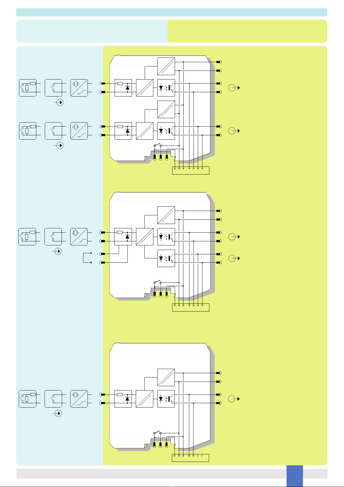
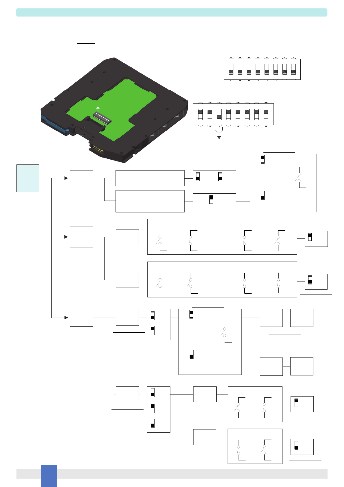
The unit can be configured for switch or proximity detector (EN60947-5-6, NAMUR), NO or NC and for NO or NC optocoupled open collector transistor output.
Each channel enables a Safe Area load to be controlled by a switch, or a proximity detector, located in Hazardous Area.
Fault detection circuit (DIP switch configurable) is available for both proximity sensor and switch equipped with end of line resistors.
In case of fault, when enabled it de-energizes the corresponding output transistor and turns the fault LED on; when disabled the corresponding output transistor repeats the input line
open or closed status as configured.
D5031D is programmable via dip switches as single input and two independent outputs. Out 2 can be programmed for output duplicating Out 1 or Fault detection Out.
In case of duplication, transistor driving can be independently configured for each output.
In case of fault output, transistor driving can be programmed as normally close or normally open.
Mounting on standard DIN-Rail, with or without Power Bus, or on customized Termination Boards, in Safe Area / Non Hazardous Location or in Zone 2 / Class I,
Division 2 or Class I, Zone 2.
Functional Safety Management Certification:
G.M. International is certified by TUV to conform to IEC61508:2010 part 1 clauses 5-6 for safety related systems up to and included SIL3.
Technical Data
Characteristics
Supply: 24 Vdc nom (18 to 30 Vdc) reverse polarity protected, ripple within voltage limits 5 Vpp, 2 A time lag fuse internally protected.
Current consumption @ 24 V: 22 mA for 2 channels D5031D, 12 mA for 1 channel D5031S with short circuit input and transistor closed, typical.
Power dissipation: 0.53 W for 2 channels D5031D, 0.30 W for 1 channel D5031S with 24 V supply voltage, short circuit input and transistor closed, typical.
Isolation (Test Voltage): I.S. In/Out 2.5 KV; I.S. In/Supply 2.5 KV; I.S. In/ I.S In 500 V; Out/Supply 500 V; Out /Out 500 V.
Input switching current levels: ON 2.1 mA (1.9 to 6.2 mA range), OFF 1.2 mA (0.4 to 1.3 mA range), switch current 1.65 mA ± 0.2 mA hysteresis.
Fault current levels: open fault 0.2 mA, short fault 6.8 mA (when enabled both faults de-energize channel transistor with single channel unit D5031S or
de-energize channel transistor with D5031D used as dual channel unit or actuate the fault transistor out with D5031D used as fault signaling unit).
Input equivalent source: 8 V 1 Ktypical (8 V no load, 8 mA short circuit).
Output: voltage free SPST optocoupled open-collector transistor.
Open-collector rating: 100 mA at 35 Vdc (1.5 V voltage drop).
Leakage current: 50 µA at 35 Vdc.
Response time: 100 µs.
Frequency response: 5 KHz maximum.
Compatibility:
CE mark compliant, conforms to Directive: 2014/34/EU ATEX, 2014/30/EU EMC, 2014/35/EU LVD, 2011/65/EU RoHS.
Environmental conditions:
Operating: temperature limits – 40 to + 70 °C, relative humidity 95 %, up to 55 °C.
Storage: temperature limits – 45 to + 80 °C.
Max altitude: 2000 m a.s.l.
Safety Description:
ATEX: II 3(1)G Ex ec [ia Ga] IIC T4 Gc, II (1)D [Ex ia Da] IIIC, I (M1) [Ex ia Ma] I
IECEx / INMETRO: Ex ec [ia Ga] IIC T4 Gc, [Ex ia Da] IIIC, [Ex ia Ma] I,
UL: NI / I / 2 / ABCD / T4, AIS / I, II, III / 1 / ABCDEFG, AEx nA [ia Ga] IIC T4 Gc
C-UL: NI / I / 2 / ABCD / T4, AIS / I, II, III / 1 / ABCDEFG, Ex nA [ia Ga] IIC T4 Gc
FM: NI-AIS / I / 2 / ABCD /T4, AIS / I,II,III / 1 / ABCDEFG, I / 2 / AEx nA [ia] / IIC /T4
FMC: NI-AIS / I / 2 / ABCD /T4, AIS / I,II,III / 1 / ABCDEFG, I / 2 / Ex nA [ia] / IIC /T4
EAC-EX: 2Ex nA [ia Ga] IIC T4 Gc X, [Ex ia Da] IIIC X, [Ex ia Ma] I X
CCC: Ex nA [ia Ga] IIC T4 Gc; [Ex ia Ga] IIC; [Ex iaD]
UKR TR n. 898: 2ExnAiaIICT4 X, ExiaI X
associated apparatus and non-sparking electrical equipment.
Uo/Voc = 10.5 V, Io/Isc = 22 mA, Po/Po = 56 mW at terminals 7-8, 9-10.
Um = 250 Vrms, -40 °C Ta 70 °C.
Approvals:
BVS 10 ATEX E 113 X conforms to EN60079-0, EN60079-7, EN60079-11.
IECEx BVS 10.0072 X conforms to IEC60079-0, IEC60079-7, IEC60079-11.
INMETRO DNV 13.0109 X conforms to ABNT NBR IEC60079-0, ABNT NBR IEC60079-11, ABNT NBR IEC60079-15, ABNT NBR IEC60079-26.
UL & C-UL E222308 conforms to UL913, UL 60079-0, UL60079-11, UL60079-15,
ANSI/ISA 12.12.01 for UL and CSA-C22.2 No.157-92, CSA-E60079-0, CSA-E60079-11, CSA-C22.2 No. 213 and CSA-E60079-15 for C-UL.
FM 3046304 and FMC 3046304C conforms to Class 3600, 3610, 3810, 3611,
ANSI/ISA-60079-0, ANSI/ISA-60079-11, ANSI/ISA-60079-15, C22.2 No.142, C22.2 No.157, C22.2 No.213, C22.2 No. 60079-0, C22.2 No. 60079-11, C22.2 No. 60079-15.
RU -IT.EX01.B.00018/19 conforms to GOST 31610.0, GOST 31610.11, GOST 31610.15.
CCC n. 2020322316000978 conforms to GB 3836.1, GB3836.4, GB3836.8, GB12476.1, GB12476.4
C16.0036 X conforms to 7113, 22782.5-78, I 60079-15.
TÜV Certificate No. C-IS-236198-04, SIL 2 / SIL 3 conforms to IEC61508:2010 Ed. 2.
TÜV Certificate No. C-IS-236198-09, SIL 3 Functional Safety Certificate conforms to IEC61508:2010 Ed.2, for Management of Functional Safety.
DNV Type Approval Certificate No. TAA00001U0 and KR No.MIL20769-EL002 Certificates for maritime applications.
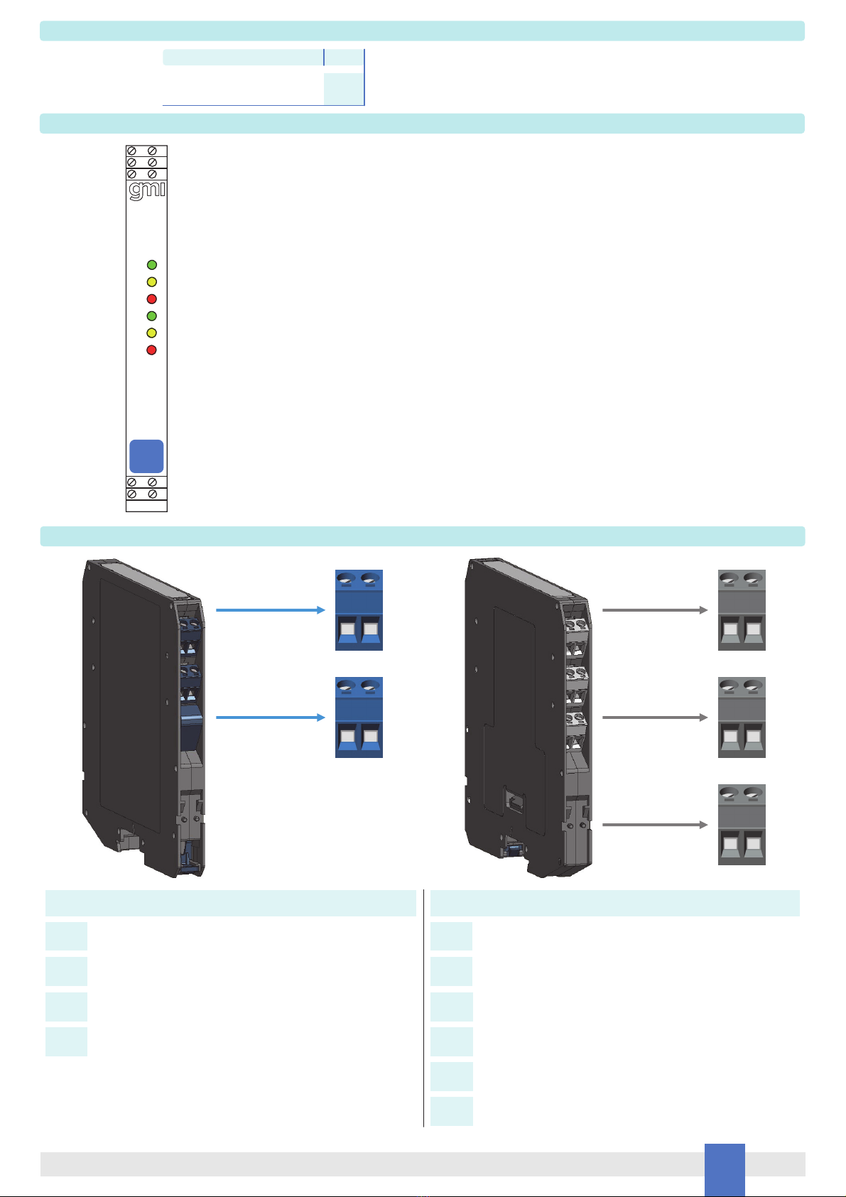
Mounting:
EN/IEC60715 TH 35 DIN-Rail with or without Power Bus or on customized Termination Board.
Weight: about 130 g D5031D, 110 g D5031S.
Connection: by polarized plug-in disconnect screw terminal blocks to accommodate terminations up to 2.5 mm2.
Location: installation in Safe Area/Non Hazardous Locations or Zone 2, Group IIC T4 or Class I, Division 2, Group A,B,C,D, T4 or Class I, Zone 2, Group IIC, T4.
Protection class: IP 20.
Dimensions: Width 12.5 mm, Depth 123 mm, Height 120 mm.
FSM
SIL 3