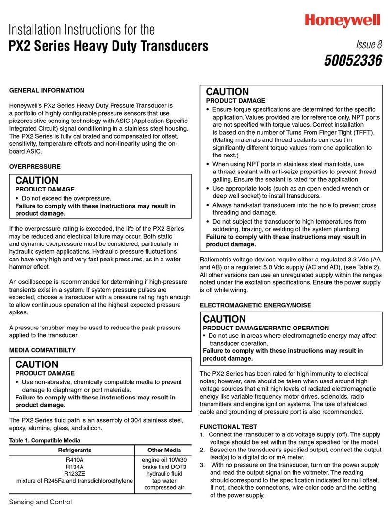
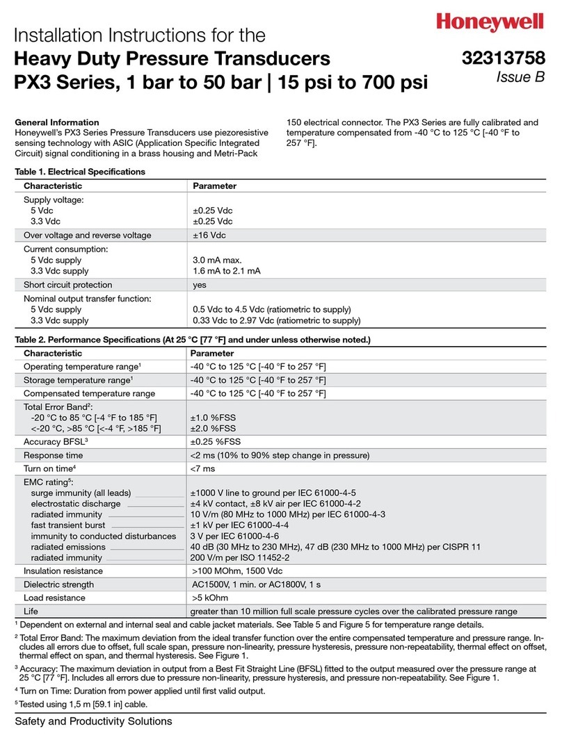
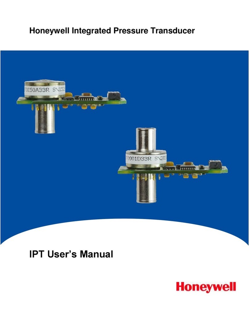
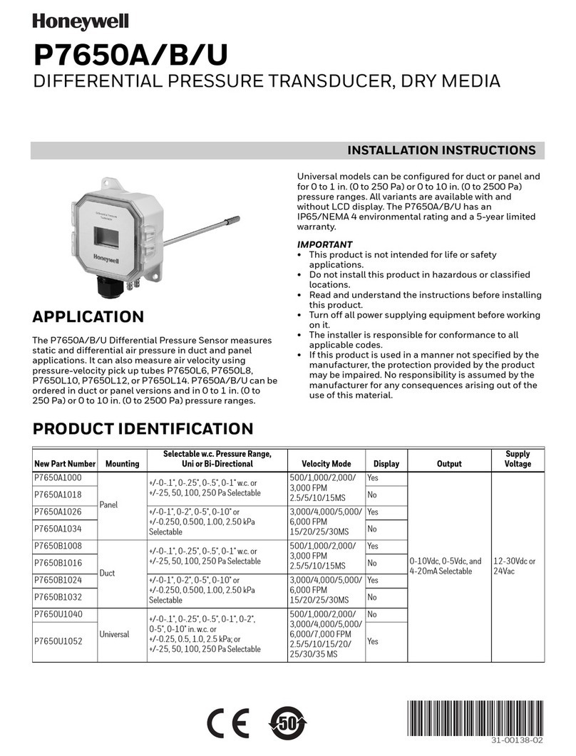
Honeywell PPT2 User manual

Chipsmall Limited consists of a professional team with an average of over 10 year of expertise in the distribution
of electronic components. Based in Hongkong, we have already established firm and mutual-benefit business
relationships with customers from,Europe,America and south Asia,supplying obsolete and hard-to-find components
to meet their specific needs.
With the principle of “Quality Parts,Customers Priority,Honest Operation,and Considerate Service”,our business
mainly focus on the distribution of electronic components. Line cards we deal with include
Microchip,ALPS,ROHM,Xilinx,Pulse,ON,Everlight and Freescale. Main products comprise
IC,Modules,Potentiometer,IC Socket,Relay,Connector.Our parts cover such applications as commercial,industrial,
and automotives areas.
We are looking forward to setting up business relationship with you and hope to provide you with the best service
and solution. Let us make a better world for our industry!
Contact us
Tel: +86-755-8981 8866 Fax: +86-755-8427 6832
Email & Skype: [email protected]om Web: www.chipsmall.com
Address: A1208, Overseas Decoration Building, #122 Zhenhua RD., Futian, Shenzhen, China

Honeywell Precision Pressure Transducer 2
PPT2 User’s Manual

ADS-14221, PPT2 User Manual October, 2016
2 of 85
ADS-14221 Rev. 10/16
For more information, visit us online at www.pressuresensing.com
No part of this manual may be reproduced or transmitted in any form or by any means, electronic or mechanical,
including photocopying and recording, for any purpose, without the express written permission of Honeywell, Inc.
Honeywell reserves the right to make changes to any products or technology herein to improve reliability,
function or design. Honeywell does not assume any liability arising out of the application or use of any product
or circuit described herein; neither does it convey any license under its patent rights nor the rights of others.

ADS-14221, PPT2 User Manual October, 2016
3 of 85
Table of Contents
Table of Contents ................................................................................................. 3
1.0 Product Overview.......................................................................................... 4
2.0 Getting Started.............................................................................................. 5
3.0 PPT2 Command Summary ........................................................................... 9
4.0 Terminology ................................................................................................ 17
5.0 Command Descriptions (alphabetical order)............................................... 21
6.0 Electrical Connections ................................................................................ 75
7.0 Installation Recommendations, Cautions and Materials of Construction .... 77
8.0 Firmware Errata .......................................................................................... 79
Appendix A: PPT2 Binary Command Format for P3 and P4 Commands:.......... 80
Appendix B: ASCII Table .................................................................................... 83
Appendix C: Setting an Analog Pressure Set Point............................................ 84
Appendix D: RAM Initialization ........................................................................... 85

ADS-14221, PPT2 User Manual October, 2016
4 of 85
1.0 Product Overview
The Honeywell Model PPT2 Precision Pressure Transducers provide high accuracy pressure readings in both
digital and analog form. The first-time user will be able to use the PPT2 within minutes, yet capability exists to
configure the PPT2 to optimize performance in the User’s specific applications. Throughout this User’s Manual,
the PPT2 may be referred to as Precision Pressure Transducer.
The heart of the PPT2 measuring system is a silicon piezoresistive sensor which contains both pressure and
temperature-sensitive elements. Digital signals representing temperature and pressure are processed by the
PPT2 microprocessor to produce calibrated, temperature-compensated pressure readings over the entire
operating temperature and pressure range.
Both the analog and digital outputs are internally corrected over the full operating range. The PPT2 has a digital
accuracy of 0.075% of full scale (FS). Note that full scale for a 20 psig and a 20 psia is 20 psi, but for a 20 psid it
is 40 psi, the sum of + Full scale and – Full Scale. This is important to note when determining the accuracy
allowance.
The PPT2 receives commands and sends digital data using either an RS-232 serial port or a multi-drop RS-485
serial port of a computer. (Note: many newer computers will have only USB ports, no RS-232 or RS-485 ports. A
USB converter can be used to provide the required RS-232 or RS-485 port.)
Using the RS-232 type PPT2, up to 89 units can be connected in a ring configuration to a single serial port of a
computer. The RS-485 type PPT2 allows up to 89 PPT2’s to be connected to a two-wire multi-drop bus. Group
(multicast) addressing allows up to nine groups of PPT2’s to be addressed with a single command. Global
(broadcast) addressing will send a command to all PPT2’s on the serial bus.
Any computer having a serial port and terminal emulation software can be connected to the PPT2 to allow the
user to set baud rates, reading rates, reading resolution, units of pressure and other choices. (User modified
functions must be set through the digital interface, using a computer with a serial port). The user-modified
functions may either be used temporarily, until the PPT2 is powered down, or may be stored in the PPT2 internal
EEPROM to automatically configure the PPT2 each time power is applied.
Analog output from the PPT2 16-bit digital-to-analog converter may be obtained without a host computer.

ADS-14221, PPT2 User Manual October, 2016
5 of 85
2.0 Getting Started
2.1 OVERVIEW
The first-time user should approach the PPT2 in a manner analogous to using a word processor program; i.e.,
many features are available but one may begin by using only those of interest at the moment.
As shipped from the factory, the default settings provide a pressure transducer that will be usable for many
applications. Once the user is familiar with the performance and command structure, changes may be made and
stored using the ‘Store Parameters’ (SP) command. Once stored, the user-defined settings are activated each
time the PPT2 is powered up. This tailors the performance of the PPT2 to meet the needs of a particular
application.
2.2 EQUIPMENT NEEDED
To prepare the PPT2 for operation, three items are needed:
• A mating connector with proper wiring connections (see connector part number and wiring diagrams in
Section 6);
• A DC power supply;
• A source of pressure that is properly matched to the range and type of the PPT.
To operate the PPT2 in the analog output mode, one additional item is needed:
• Voltage Output - A five digit voltmeter with 0-5 volt range connected between Analog Out and Signal
Common. A computer is not required to read the Analog output.
To operate the PPT2 in the digital output mode, one additional item is needed:
• A computer, or host processor, having an RS-232 or RS-485 serial port (or suitable USB adapter) and
terminal emulation program.
The wiring diagram designates which PPT2 pins must connect to the computer “send”, “receive” and
“common” pins for proper communications.
2.3 TERMINAL PROGRAM SETTINGS
Enter the following settings in the terminal program:
Baud Rate: 9600
Start Bits: 1
Data Bits: 8
Stop Bits: 1
Parity: None
Attach a line feed to the carriage return.
Turn the local echo ON.
When shipped from the factory, the PPT2 is set to a baud rate of 9600, 1 start bit, 8 data bits with no parity and 1
stop bit. If the baud rate has been subsequently changed, and is unknown, it will be necessary to search all baud
rate values to reestablish communication. See the BP command description in Section 5 of this manual for
possible settings.

ADS-14221, PPT2 User Manual October, 2016
6 of 85
2.4 INITIAL TURN-ON RESPONSE
Analog Output
The factory default analog output will provide a voltage (range 0-5V) which, when ambient pressure is applied to
the PPT2,reads:
Pressure Type
Voltage Output
(@ zero applied pressure)
Gauge units
0 volt
Differential units
2.5 volts
Absolute units
A voltage representing atmospheric pressure
Digital Output
Once the wiring connections and terminal program settings are complete, the PPT2 will automatically send the
following response (or similar to) when power is applied. This reply will be generated any time power to the PPT2
is cycled off and on.
Typical Reply:
?00PPT2___10__psid
The “?00” indicates a default address device called a “null address”. This PPT2 has not yet been assigned an ID
number by the user, so it assumes the null address. The “PPT2___10__psid ” indicates a 10 psi differential
device.
2.5 COMMAND FORMAT
Any command interaction with the PPT2 requires electrical connection to the RS-232 or RS-485 serial
communications pins. There are two basic types of commands – action directing commands and information
requesting commands. These are described in Commands – Section 5.
Typical PPT2 commands have the form *ddcc = nnn <cr>
Where:
* is the command header character
dd is the integer address of the PPT (00 – 89)
cc is a command (refer to Commands – Section 5 for a complete description of commands)
= equal sign (required in some commands)
nnn additional characters (required in some commands)
<cr> carriage return is required to end all commands (do not type “<cr>”, press the ENTER/RETURN key)

ADS-14221, PPT2 User Manual October, 2016
7 of 85
2.6 STEP-BY-STEP EXAMPLES (For a single PPT2 connection, default 00 address)
READ A SINGLE PRESSURE
Once the PPT2 is powered up and connected to a computer, enter the following command: (do not type “<cr>”,
press the ENTER/RETURN key)
User Types on the keyboard:
*00P1 <cr>
PPT2 Response:
?00CP=14.4582
Where
* indicates the start of a command
00 is the null address of the PPT2 (see note below)
P1 is the command to read the most current pressure
Note: The “?” indicates the response from a null addressed PPT2– one which has not been assigned a device ID.
A null address, 00, is coded into each PPT2 at the factory. Refer to the ID command in Section 5 for a description
of addresses and responses.
The “CP=14.4582” indicates a compensated pressure of 14.4582 psi. (Your unit may not show this specific
reading, depending on the applied pressure it is measuring.)
SET DEVICE ID
To give the PPT2 an assigned address of 01 up to 89, enter the following commands:
*00WE<cr> This enables the PPT2 to change a parameter in RAM
*00ID=01<cr> This sets the null addressed PPT2 to device ID=01.
Note: The new device ID is now used in subsequent commands
*01S=<cr>
Response: #01S=00052036 (serial number)
The “#” now replaces the “?” in the header and indicates the PPT2 response is from an address-
assigned unit.
READ PRODUCTION DATE
To read the production date, enter the following command:
*01P=<cr>
Response: #01P=04/13/11

ADS-14221, PPT2 User Manual October, 2016
8 of 85
READ CONTINUOUS PRESSURE
For continuous pressure readings (factory default rate = 5 per second) enter the following command:
*01P2<cr> This enables a continuous stream of compensated pressure readings to flow into the
terminal program.
$*99IN<cr> This is the best way to stop the continuous pressure reading commands. The ‘$’
character temporarily stops, or suspends, the digital output of the PPT2. The *99IN
command stops the continuous pressure or temperature readings.
CHANGE TO A NEW READING RATE
Enter the following command:
*01WE <cr> This enables the PPT2 RAM to accept a changed parameter.
*01I=M200<cr> This sets the integration time to value M200, which corresponds to an output reading
every 2 seconds.
The reading rate will change to one every 2 seconds. I= is an abbreviation for Integration time, which determines
how long to accumulate corrected pressure values between readings. Each integration period gathers the data for
one pressure reading output (see Section 4.2 What is integration?). The range of integration times can be set by
specifying readings per second (I=R50 for 50 readings/sec) or in 10 millisecond intervals (I=M600 for 6 seconds).
The factory-set integration time is 200 milliseconds or 5 readings per second (I=M20).
The output data rate can also be altered by use of the idle count (IC) command or by changing the operating
mode (OP) command. See Section 5 for description of these commands.
REPEAT THE READ CONTINUOUS PRESSURE STEP ABOVE
Notice the slower output rate of one reading every 2 seconds.
TRY OTHER COMMANDS
Experiment with other commands to become familiar with the command structures. A short overview of each
command with input and response examples is shown in Section 3 Command Summary. See Section 5—
Commands for complete command descriptions. Until an SP=ALL command is executed, no changes will be
stored in the PPT2 EEPROM. Re-apply the power or send an IN=RESET command to revert to the settings last
saved in EEPROM.

ADS-14221, PPT2 User Manual October, 2016
9 of 85
3.0 PPT2 Command Summary
The PPT2 command set is summarized in Table 1.0 – Command List. A more detailed description of each
command can be found in the subsequent command descriptions in Section 5.
Table heading explanations for Table 1.0 – Command List:
Command Code: Two-character code (cc) in the command format (see Section 2.5). The
command code characters may be one letter followed by an ‘=’ equal
sign, two letters, or a letter and a number. The letters are not case
sensitive; i.e. either upper case or lower case may be used. (The PPT2
internally converts all lower case characters to upper case.)
Action Directing Command: Does this command change the PPT2 configuration?
Yes – The command changes the PPT2 configuration as an action
directing command.
No – The command is only an Information Request Command.
Information Request Command: The command initiates a response (output) from the PPT2, with the
output content being specific to that particular PPT2.
Sequential Response with Group or Global Address:
Commands that begin with a group or global address (ID=90-99), are
passed through the PPT2 ring configuration network from one device to
the next and eventually end up back at the host computer. The PPT2
response is sent with the command through the network.
Before – The PPT2 response is sent before the group or global
command is repeated.
After – The PPT2 response is sent after the group or global command is
repeated.
No – The PPT2 just passes the command through the network with no
response.
Input or Output: Is information input to the PPT2 or output from the PPT2?
In – Command is only used to input (action direct command) to the
PPT2.
Out – Command is only used to request output (Information Request
Command ) from the PPT2.
Both – Command can be used for either IN or OUT purposes.
Requires Write Enable: Is a WE command required before for this command?
Yes – When sent as an action directed command, it must be preceded
by a WE command.
No – Never requires a WE command beforehand. These are Information
Request Commands.
Terminates Continuous Commands:
Will this command stop the PPT2 digital output flow?
Yes – This command will end the continuous flow of the P2, P4, or T2
replies.
No – Command will not stop the continuous digital output flow.

ADS-14221, PPT2 User Manual October, 2016
10 of 85
Write to EEPROM: Can this command have parameters stored in EEPROM?
Yes – Parameter values associated with this command may be stored in
EEPROM.
No – Cannot store anything from this command in EEPROM.
All – Cause all parameters to be stored in EEPROM.
Write to DAC: Can this command be written to the DAC?
Yes – Command may be directed to the DAC.
No – Command is not associated with the DAC.

ADS-14221, PPT2 User Manual October, 2016
11 of 85
Table 1.0 – Command List, Grouped by Function
See previous page for descriptions of the table headings.
Command
Code
Action
Directing
Command
Sequence of
Response with
(90-99)
Addresses
Input or
Output
Type
Requires
Write
Enable
Terminates
Continuous
Commands
Can Write
to
EEPROM?
Can Write
to DAC?
Command Description
Pressure Readings
P1 No Before (5) Out No No No No
Pressure, Single, ASCII Format
P2 No (3) After Out No Yes (8) No No
Pressure, Continuous, ASCII Format
P3 No Before (5) Out No No No No
Pressure, Single, Binary Format
P4 No (3) After Out No Yes (8) No No
Pressure, Continuous, Binary Format
Pressure Units
DU Yes Before Both Yes (6) No Yes (9) No
Display Units Control
U= Yes After (4) Both Yes (6) No Yes (9) No
User Supplied Display Units
Pressure Sensor Temperature Readings
T1 No Before (5) Out No No No No
Sensor Temperature, Single, °C
T2 No (3) After Out No Yes (8) No No
Sensor Temperature, Continuous, °C
Transducer Information
ID Yes Before Both Yes (6) No Yes (9) No
Identification Number
M= Yes After (4) Out No No No No
Maximum Full Scale Pressure
P= No After (4) Out No No No No
Production Date
S= No After (4) Out No No No No
PPT2 serial number
V= No After (4) Out No No No No
PPT2 Firmware Version
Pressure Reading Modifiers
I= Yes After (4) Both Yes (6) No Yes (9) No
Integration Time
IC Yes Before Both Yes (6) No Yes (9) No
Idle Count Parameter
CM Yes Before Both Yes (6) No Yes (9 No Compatibility Mode (new command)
DS Yes Before Both Yes (6) No Yes (9) No
Deadband and Sensitivity Control
Pressure Window Customization, Calibration, and Control
F= Yes After (4) Both Yes (6) No Yes (9) No
Customized Full Scale Pressure
Range
T= Yes After (4) Both Yes (6) No Yes (9) No
Set Tare Value
TC Yes Before Both Yes (6) No Yes (9) No
Tare Control Switch
X= Yes After (4) Both Yes (6) No Yes (9) No
Slope 1, User Compensation Control
Y= Yes After (4) Both Yes (6) No Yes (9) No
Slope 2, User Compensation Control
Z= Yes After (4) Both Yes (6) No Yes (9) No
Offset, User Compensation Control
Analog Customization, Calibration, and Control
AN Yes Before Both Yes (6) No Yes (9) No Analog Range Setting
DX Yes After (4) Both Yes (6) No Yes (9) No
DAC Slope Compensation Control
(new command)
DZ Yes After (4) Both Yes (6) No Yes (9) No
DAC Offset Compensation Control
(new command)
H= Yes After (4) Both Yes (6) No Yes (9) Yes (11) Highest Analog Voltage

ADS-14221, PPT2 User Manual October, 2016
12 of 85
L= Yes After (4) Both Yes (6) No Yes (9) Yes (11) Lowest Analog Voltage
O= Yes After (4) Both Yes (6) No Yes (9) Yes (11) Offset Pressure Window (analog
output)
W= Yes After (4) Both Yes (6) No Yes (9) Yes (11) Width of Analog Window
N= No (3) After (4) Both No (7) No No Yes (11) Send Number to DAC (force analog
output)
Diagnostic and Reset Control
CK No After (4) Out No No No No
Check Memory
IN No (2) No In No Yes No No
Initialize PPT2 Microprocessor
RS No Before (5) Out No No No No
Read Status
Operating Parameters
BP Yes After (4) In Yes Yes Yes (9) No
Baud Rate and Parity Setting
DA Yes Before Both Yes (6) No (12) Yes (9) Yes (10) Digital and Analog Control
DO Yes Before Both Yes (6) No Yes (9) No
Default Operating Parameters
MO Yes Before Both Yes (6) No Yes (9) No
Power-up Mode
OP Yes Before Both Yes (6) No Yes (9) No
Operating Mode Parameters
TO Yes Before Both Yes (6) No Yes (9) No
Transceiver Operating Parameters
Utility
A= No After (4) Both Yes No Yes (9) No Data string A
B= No After (4) Both Yes No Yes (9) No Data string B
C= No (1) After (4) Both Yes
D= No (1) After (4) Both Yes No Yes (9) No Data string D
FD Yes No In Yes No No No
Restore Factory Defaults (new
command)
NE No No In No No Yes (9) Yes
Analog Output Enable
SP Yes No In Yes No All No
Store RAM parameters in EEPROM
WE Yes No In No No No No
Write enable for RAM/EEPROM
$
Suspend Continuous Readings
.

ADS-14221, PPT2 User Manual October, 2016
13 of 85
COMMAND LIST NOTES
(1) The C= and D= commands do not change the mode of operation but do provide a user supplied
power-up message if configured using the MO command.
(2) The IN command does not change the operating parameters stored in RAM, but it does stop
continuous readings (P2, P4, T2 commands). If the IN=RESET command is sent, then any
parameters that were stored in RAM, and were not stored in the EEPROM with a SP command, will
default to the last stored EEPROM value. This may cause a change in the operational parameters as
well as a configuration change.
(3) The P2, P4, and T2 commands do not change the operating parameters, only activate continuous
readings. The N= command does not change any operating parameter values only the DAC analog
output voltage.
(4) When this information request command is sent to a group or global address, the PPT2s do not
immediately respond with their output. The command is repeated from PPT2 to PPT2 in a ring
configuration network , and eventually returned to the host processor. Each PPT2 appends its own
response as it forwards the command. Also, this command requires more time for execution, of
EEPROM reads , so responses from more than one PPT2 are not received in any guaranteed order.
During the execution of one of this command, if another command is received that is an “After” type,
whether globally, group, or individually addressed, the received command is rejected and the
command read status error (see RS command) is set.
(5) These commands may cause sequential responses from any, all or none of the addressed units. A
sequential response is when the PPT2 reply is sent before the global or group command through the
network. See the individual command descriptions for detailed information.
(6) These commands only require a write enable (WE) when used in the action directing form. For these
commands the WE command provides a single occurrence write enable for RAM update. That is,
only the next instruction is written to RAM. The WE=RAM command provides continuous write
enables for RAM for multiple command updates. The continuous RAM enable is active until a WE is
sent.
(7) The N= command requires an NE command enable when used to send information. The NE
command provides single occurrence write enable for analog control. The NE=DAC command can
be used to provide continuous write enable for analog control.
(8) These commands terminate an active continuous reading command (P2, P4, T2) and initiate the
new one.
(9) These commands can be used to change RAM contents which can then be written to the EEPROM
using the SP=ALL command.
(10) The DA command does not write to the DAC but it does allow the DAC to be controlled by the PPT2
input pressure value or by a digital value applied by the N= command.
(11) These commands only write to the DAC when used in the action directing form.
(12) A P2 mode will be cancelled when a DA= A, C, F, G or N parameter is selected. A P4 mode can be
cancelled when a DA=A, E, M or N parameter is selected.

ADS-14221, PPT2 User Manual October, 2016
14 of 85
COMMAND FORMAT
Communication between the host or control processor and a PPT2 is accomplished by message transfers, or
commands and replies. Communications initiated by the host processor to one or more PPT2s are called
commands and must begin with an ‘*’ header character. (For RS-485 PPT2s, alternate header characters are
available, using the MO command.) All commands must be terminated by a <cr> (carriage return or ENTER key).
Communications initiated by a PPT2 to the host are called responses or replies, and begin with one of ten unique
header characters (2 for ASCII responses, 8 for binary format responses).
Commands may request information from one or more PPT2s such as read pressure, or direct action to one or
more PPT2s such as change a command value or operating mode.
Typical PPT2 command format: *ddcc = nnn <cr>
Where: * is the command header character
dd is the decimal address of the command message (00-99)
cc is the command code. Command code characters sent to the PPT2 are not case
sensitive; i.e.,
either an upper case or lower case may be used. Responses from the PPT2 will have
capitalized command code characters. Example: #01CP=14.2426
= equal sign (required in some commands)
nnn additional characters (required in some commands)
<cr> carriage return (the ENTER key on a standard keyboard)
Note: For RS-485 mode, alternate headers are available. (see MO command)
In an RS-232 network, when manually applying commands to one or more PPT2s which are in the continuous
send mode (P2, P4, T2, ), the special header character ‘$’ should be used to suspend all PPT2 transmissions
while the command message is being typed. The ‘$’ is immediately followed by the normal command format.
In the case of an RS-232 network, if an erroneous command is sent to the PPT2, it is echoed back to the host as
soon as the PPT2 recognizes it as an invalid command. For example, if the user tries to enter *01S2=15 (S2 is
not a valid command for the PPT2), *01S2 would immediately be echoed back. The other instance of an echoed
command is when a group or global address command (ID = 90 to 99) is sent, such as *99I=R15<cr>.
Group/global addresses will always echo the command back to the host processor after being read by all PPT2s
in the network.

ADS-14221, PPT2 User Manual October, 2016
15 of 85
PRESSURE READING DECIMAL POSITION
The table below shows the number of decimal place variations with respect to PPT2 full scale - the number of
digits to the right and left of the decimal place. This is valuable when converting a binary format number so that
the proper decimal position can be determined.
If CM=ON (PPT Compatibility Mode), subtract 1 from the “Digits to Right“ column of the table below.
Full Scale *
(current Display Units)
Digits
to Left
Digits
to
Right
Digit to Left if
-1< reading < 1
Negative Values
≥9,000,000 8 1 0, padded w/ leading spaces “-“ inserted after “=”
≥900,000 and <
9,000,000
7 1 0, padded w/ leading spaces “-“ inserted after “=”
≥90,000 and <
900,000
6 1 0, padded w/ leadings
spaces
“-“ inserted after “=”
≥9,000 and < 90,000 5 1 0, padded w/ leading spaces “-“ inserted after “=”
≥900 and < 9000 4 2 0, padded w/ leading spaces “-“ inserted after “=”
≥90 and < 900 3 3 0, padded w/ leading spaces “-“ inserted after “=”
≥9 and < 90 2 4 0, padded w/ leading space “-“ inserted after “=”
≥0.9 and < 9 1 5 0 “-“ inserted after “=”
≥0.09 and < 0.9 1 6 0 or “-“ Leading zero replaced with “-“
≥0.009 and < 0.09 1 7 0 or “-“ Leading zero replaced with “-“
≥0.0009 and < 0.009 1 8 0 or “-“ Leading zero replaced with “-“
< 0.0009 1 9 0 or “-“ Leading zero replaced with “-“
* For differential units, when determining decimal point position the Full Scale is the maximum positive pressure
(5 psid = 5, 20 psid = 20, etc)
Whether OP=E (extended) or OP=F (fixed) also has an impact upon how the data is displayed.
Example readings:
5 psid, OP=E, F=0 (5 psi)
?00CP=-0.00141 (negative reading > -1)
?00CP=0.02373 (positive reading < 1)
?00CP=-3.00537 (negative reading < -1)
?00CP=2.36973 (positive reading > 1)
5 psid, OP=F, F=0 (5 psi)
?00CP=-0.01442 (negative reading < -1)
?00CP= 0.00454 (positive reading < 1)
?00CP=-4.37939 (negative reading < -1)
?00CP= 3.80066 (positive reading > 1)
5 psid, OP=E, F=0.8 psi
?00CP=-.551017 (negative reading)
?00CP=0.804965 (positive reading)
5 psid, OP=F, F=0.8 psi
?00CP=-.779264 (negative reading)
?00CP=0.733452 (positive reading)

ADS-14221, PPT2 User Manual October, 2016
16 of 85
PPT Commands/Parameters Not Implemented in PPT2
DA={O|S|T|U} Digital and Analog Control
DO=N|P Noise Protection in P4 mode
NE=ZER[O,V] NE Command Extension
RR Reading Rate
S2 Speed Shift x2
S5 Speed Shift at 50msec Intervals
SI Synchronize Integration Cycles
T3 Temperature, Single, °F
T4 Temperature, Continuous, °F
TO=R|M Special Ring and Multi-drop protocol functionality
TO=C|A|S|H Synchronization functionality
TO=N|P Normal and Prompted RS-485 group/global read operations
~ Command Header for Binary DAC Values

ADS-14221, PPT2 User Manual October, 2016
17 of 85
4.0 Terminology
4.1 WHAT IS INTEGRATION?
The input pressure is converted to an analog electrical signal at the pressure sensor. This signal
feeds into a delta-sigma analog-to-digital (A/D) converter where it is changed into a digital signal
representing the pressure value. During the A/D conversion cycle, the signal is integrated over time.
That is, the pressure reading is averaged (integrated) over the A/D conversion cycle so the resultant
digital value is the summation of the average pressures observed during the cycle. This conversion
cycle is controlled by the user with the Deadband and Sensitivity (DS), Idle Count (IC), and
Integration (I=) commands.
4.2 PRESSURE READING CONTROL
The PPT2 commands allow considerable flexibility in tailoring pressure acquisition times, reading
windows, thresholds, and output rates. These are controlled by 4 commands: Deadband and
Sensitivity (DS), Integration (I=), Idle Count (IC), and OPerating mode (OP). The user may control
these attributes in three ways:
First, the internal integration time may be controlled over a range of 1 reading every 10 seconds up
to 1000 readings per second. This is controlled using the ‘Integration’ (I=) command. Pressure values
are calculated every millisecond. The integration time is used to control the amount of averaging of
these pressure values to create each pressure value. The integration time can be set within a range
of 1 to 1000 readings/sec using the I=Rn form, or a range of 10 msec to 10 sec/reading using the
I=Mn form. The values for ‘n’ range from 1 to 1000 for both the rate (Rn) form and the millisecond
(Mn) form.
Second, the integration cycles may be spaced with idle periods that cause pressure reading times to
increase to as long as one every 42.67 minutes. The Idle Count (IC) command will insert, or skip,
from 0 to 255 idle periods equal to the integration time. If the integration time is set to the maximum,
10 sec/reading, and an idle count of 255 is selected, then the time between readings = 10 sec. x 256
= 42 minutes, 40 seconds.
Third, the reading rate may be controlled so pressure readings are obtained only when pressure
changes occur. The OPerating mode command (OP) can be set to output every reading (OP=A) or
to only output changes (OP=U). The Deadband setting in the DS command can filter a small
pressure change by not allowing the pressure output reading to vary as long as it remains within the
Power
Regulation
Digital
Serial
Data
DC
Input
Pressure
Input
PPT2
simplified block diagram
Pressure And
Temperature
Bridge Circuits
Analog
to Digital
Converter
Micro-
processo
r
RAM
0-5V
Output
RS-232 or
RS-485
Transceive
r
16-bit Digital
to Analog
Converter
EEPROM
FLASH
Raw Pressure and Temperature “Samples”
Corrected Pressure and Temperature “Values” or
Averaged Corrected Pressure and Temperature “Values”
Pressure and Temperature “Readings”
or Pressure and Temperature “Output”

ADS-14221, PPT2 User Manual October, 2016
18 of 85
deadband limits. This controls the OP command mode’s sensitivity to pressure change when the
‘output only when pressure changes’ (OP=U) option is selected.
4.3 PPT2 ADDRESSING
The PPT2 provides three levels of addressing. The lowest level of address is the individual unit
address, or device ID. This address level is used to address any single PPT2. The next level is
group address, which is separate from the device ID. All PPT2 units with the same group address
will respond to a command sent to this level address. The last is a global address, which is read by
all PPT2s on a network. The device ID can be assigned by direct command or assigned
automatically based on its position from the host processor in PPT2 network. The null address (00)
is simply a default device ID that the PPT2 automatically assumes until one is assigned. That is,
upon power-up, if there is no ID assigned, and an ID has not been stored in the EEPROM, then the
PPT2 will assign itself the “00” null address.
The individual unit address, or device ID, has an assigned range from 01-89. The null address 00 is
the factory default address for unassigned PPT2s. A unit with the null address, replies with a ‘null
address’ header. The null address header characters are ‘?’ for ASCII format (standard keyboard
alphanumeric characters ) or ‘^, &, |, or %’ for binary format (fewer data bytes that are encoded for
computer translation.) A unique device ID allows the host processor to send commands to specific
units on a bus.
The second level of addressing is a multicast, or group, address in the range of 90-98. Each unit can
be assigned a group address by the ID command. A unit responds to its group address in the same
manner as it does to its global address described below. The group addressing allows the host
processor to send commands to several units having the same group address. The factory default
group address is 90.
The highest level of addressing is the broadcast, or global, address 99. All units receive global
addressed commands. All RS-232 units respond to global commands. Only RS-485 units with as-
signed addresses will respond to global commands. An RS-485 unit with a null address will not reply
to any global command. Global addresses are not assigned but are built into the PPT2.

ADS-14221, PPT2 User Manual October, 2016
19 of 85
RS-232 Ring Network
The RS-232 network consists of a three-wire bus (TD, RD, and GD) that begins and ends at the host
processor. In general, the RS-232 electrical standard requires that the distance between units not
exceed 60 feet (18 meters). An advantage of the RS-232 network is that it interfaces directly to the
serial COM port of most personal computers (or USB to serial adaptor). The maximum number of
PPT2s with assigned device IDs on a network is 89.
A PPT2 ring network connection of six units is shown below. In this example, the Device IDs
are sequential, starting from 01, from the transmit port of the host processor around the loop. There
are two address groups, 91 and 93; each have 3 PPT2 units assigned.
Each PPT2 on a communication ring must have a unique address in order to individually receive
commands from the host processor. For example, if more than one PPT2 on a ring has a null
address, and a 00 address command is transmitted by the host, only the first null address PPT2 will
receive the command and the command is not passed on. This is the same for any address on an
RS-232 ring network.
Another advantage of the RS-232 ring network is the ability to automatically assign device IDs to
every PPT2 on the network. Since commands flow through every PPT2 on the ring, a single *99ID=01
command will assign ID=01 to the first unit, and each in the ring will assign itself the next number. As
the command is passed along, each unit adds one to the ID command. For the example network
shown above, the command will read *99ID=07 when it returns to the host processor. The form of
self-addressing will indicate the PPT2 position in the communication ring relative to the host
processor.
Every unit in the RS-232 ring network has an assigned group address. When the host processor
sends a group addressed (*90 to *98) command, that command cycles through every PPT2 and is
passed to the next one in the loop. Those units having that group address read the command, then
pass the command and reply to the next unit in the ring. Some responses pass the string of PPT2
replies before the group command while others pass the string of PPT2 replies after the group
command. See Table 1.0 for specific command types and the order of repeating the group command.
Every unit in the RS-232 ring network receives a global addressed (*99) command. All units read the
command and pass the command and their response to the next unit in the ring.
Signal Ground
ID=01
Group=91
ID=02
Group=91
ID=03
Group=93
ID=06
Group=93
ID=05
Group=91
ID=04
Group=93
GD = Signal Ground
TD = RS-232 Transmit
RD = RS-232 Receive
GD
TD
RD
RD RD RD
RDRD
RD
TD TD TD
TDTD TD
Signal Ground
Table of contents
Other Honeywell Transducer manuals
Popular Transducer manuals by other brands

Humminbird
Humminbird transducer Assembly & operating instructions

ETH-messtechnik
ETH-messtechnik DRVL Operator's manual

Airmar
Airmar M260 Owner's guide & installation instructions

Humminbird
Humminbird Transducer Installation

HBM
HBM P6A Mounting instructions

Balluff
Balluff Micropulse BTL5-A series user guide