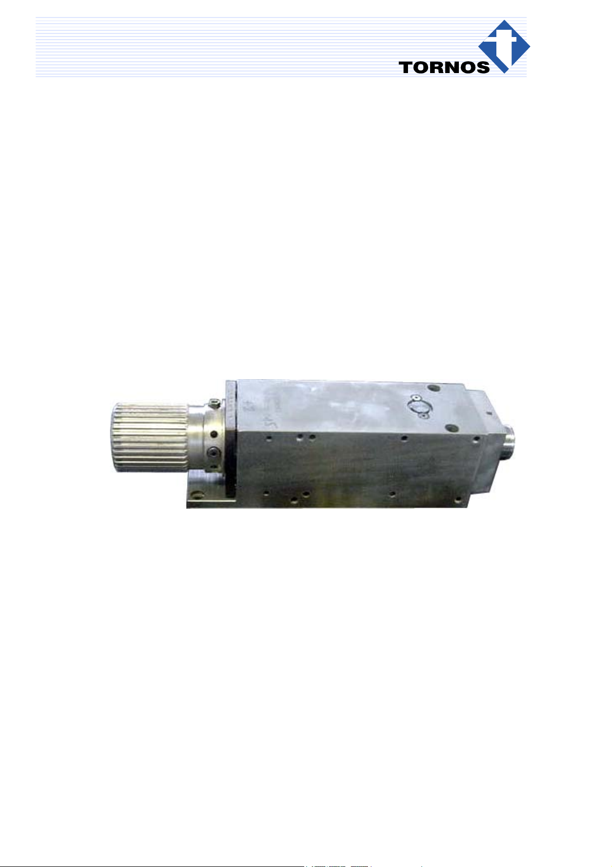
tornos DECO 10 Headstock Revision Manual
DECO Internal RP
TORNOS SA - CH-2740 MOUTIER - http://www.tornos.ch Imprimé en Suisse Copyright (c)1999-2004
DECO 10 Headstock Revision ref. 305063
DESCRIPTION - PROCEDURES en TT5501

TT5501 - DECO 10 Headstock Revision
Chap. / 2 TT5501 en - 12/04
Differentiationof degrees of risk
These instructions indicate a number of safety measure symbols which appear also on the machine and are
intended to protect the user, his/her effects and the environment from injuries and damage as applicable.
Below, you will find the safety symbols, their headings and definitions. Please, read these first before you con-
tinue.
∆Danger !
indicates a direct danger of death or serious injury.
∆Warning !
indicates an object or action which may cause death or serious injury.
∆Caution !
indicates an object or action which may cause injury or serious damage.
∆Attention !
indicates incorrect actions or such that may cause damage.
⊗Prohibition !
indicates an action or operation prohibited because of evident or alleged hazards.
⇒Info :
Gives information or comment related to safety.
⇒Note :
Gives information unrelated to safety
Important Safety Indications
∆Warning !
Read the instruction before operating the machine.
Should the user disregard the instructions of this manual, TORNOS SA declines any liability what-
soever.
∆Attention !
Certain maintenance works are absolutely necessary to ensure good operation of the machine. They
are given in the MAINTENANCE SCHEDULE on the machine
(or see Instructions: OPERATION-MAINTENANCE).
∆Caution!
TORNOS SA disclaims all responsibility for any modifications carried out by the customer to the
machine, and to its related equipment and software, without agreement ratified by
TORNOS SA.

TT5501 - DECO 10 Headstock Revision
3TT5501 en - 12/04
TABLE OF CONTENTS
1. EQUIPMENT 5. . . . . . . . . . . . . . . . . . . . . . . . . . . . . . . . . . . . . . . . . . . . . . . . . . . . . . .
2. DISMOUNTING THE HEADSTOCK 5. . . . . . . . . . . . . . . . . . . . . . . . . . . . . . . . . . .
3. CHECKING THE PARTS 7. . . . . . . . . . . . . . . . . . . . . . . . . . . . . . . . . . . . . . . . . . . . .
4. MOUNTING 8. . . . . . . . . . . . . . . . . . . . . . . . . . . . . . . . . . . . . . . . . . . . . . . . . . . . . . . .
4.1 PREPARING THE PARTS 8. . . . . . . . . . . . . . . . . . . . . . . . . . . . . . . . . . . . . . . . . . . . . . . . . . . . . . . .
4.2 MOUNTING THE PARTS 8. . . . . . . . . . . . . . . . . . . . . . . . . . . . . . . . . . . . . . . . . . . . . . . . . . . . . . . . .
5. REFILLING THE HEADSTOCK 12. . . . . . . . . . . . . . . . . . . . . . . . . . . . . . . . . . . . . . .
6. CHECKING THE HEADSTOCK 13. . . . . . . . . . . . . . . . . . . . . . . . . . . . . . . . . . . . . . .
7. BREAKING IN THE HEADSTOCK 13. . . . . . . . . . . . . . . . . . . . . . . . . . . . . . . . . . . .
8. ASSEMBLY DRAWINGS 15. . . . . . . . . . . . . . . . . . . . . . . . . . . . . . . . . . . . . . . . . . . . .
9. APPENDIX - DECO 10 BREAK-IN SHEET 17. . . . . . . . . . . . . . . . . . . . . . . . . . .


TT5501 - DECO 10 Headstock Revision
Chap. 2. / 5
TT5501 en - 12/04
1. EQUIPMENT
Assembly drawing ref. 305001
Tools ref. 758 438
Press travel ~450mm
Grease Mobile 28
Kubler NBU15
Molykote DX
Headstock filling oil ISO GV 220
Screw locking product Loctite 222
2. DISMOUNTING THE HEADSTOCK
Actions Notes
1. After dismounting the headstock from the
machine, remove : the plastic plugs (520),
the 3 screws (490) (see section E-E),
the window (040),
the tubing (080) using an M6 screw, the 2 gaskets
(see section G-G).
2. Loosen the 2 screws (530), the plug (100), the
pivot axis (090), the gaskets.
3. Loosen the 4 clamping screws (400) section J-J
a 1/2 turn and tighten the 4 screws (140) 4 to 5
turns to release the springs (660).
4. On the headstock front side, loosen the 6 screws
(410), ”screws locked” section A-A.
5. Push the flange (200) to remove the thrust ring
(650).
6. Loosen the 4 screws (430) section H-H.
7. Remove the spindle from the rear making sure to
recover the 4 springs (660) section J-J.
8. Remove the cover (120) section A-A.
⇒Note :
Refer to the assembly drawing, ref 305063.

TT5501 - DECO 10 Headstock Revision
Chap. 2. / 6 TT5501 en - 12/04
Actions Notes
9. Remove
Floating solenoid valve (230).
Cylinder (240),
gasket (580)
Thrust ring (210)
2 bleed screws (060) of the primary piston (250).
2 bleed screws (150) of the spindle.
10.Remove the gaskets from the bleed screws,
Refill plug (070) section C-C and remove the
gasket,
Primary piston (250) section A-A.
11. Cut the gaskets from the primary piston.
12.Remove the rear case (130),
Lock ring (220) and gasket (570) from the ring.
13.Remove the roller bearings (680) using appropri-
ate tools. ⇒Note :
To facilitate dismounting, the outer cage can be
removed from the roller bearings or the FACOM
bearing remover can be used.
14.Place the spindle front on the press plate.
15.Using the tool (ref. 10), press on the case (170) to
compress the spring (270).
Then release the Seeger ring (640) and remove
it.
16.Remove the case (170), the spring (270) and the
secondary piston (160) using the thrust tube
(260).
17.Loosen the nut (050).
18.Remove the inner and outer gaskets from the sec-
ondary piston.
∆Caution !
The nut is locked with loctite ; the thread is a
right-hand threading.
19.Using a rod, remove the front roller bearings (590)
of the headstock from inside the body through the
passage holes.
20.Using a press and tools (see image to right),
remove the collet (010).

TT5501 - DECO 10 Headstock Revision
Chap. 3. / 7
TT5501 en - 12/04
3. CHECKING THE PARTS
∆Caution !
CLEAN THE PARTS TO CHECK FOR CONDITION.
Actions Notes
1. Change all the damaged parts with contact rust or
wear.
2. Change the roller bearings.
3. Change the gaskets.
4. For the old spindles and the retainer spring, have
them checked for balance.
5. For the bleed screws, mount new screws (060)
with gaskets (610).

TT5501 - DECO 10 Headstock Revision
Chap. 4.2 / 8 TT5501 en - 12/04
4. MOUNTING
∆Caution !
Check the parts before mounting to make sure they are not defective.
4.1 PREPARING THE PARTS
Actions Notes
1. Lightly grease the gaskets and the mechanical
surfaces in contact.
⇒Note :
Use the grease Kubler NBU15
4.2 MOUNTING THE PARTS
Actions Notes
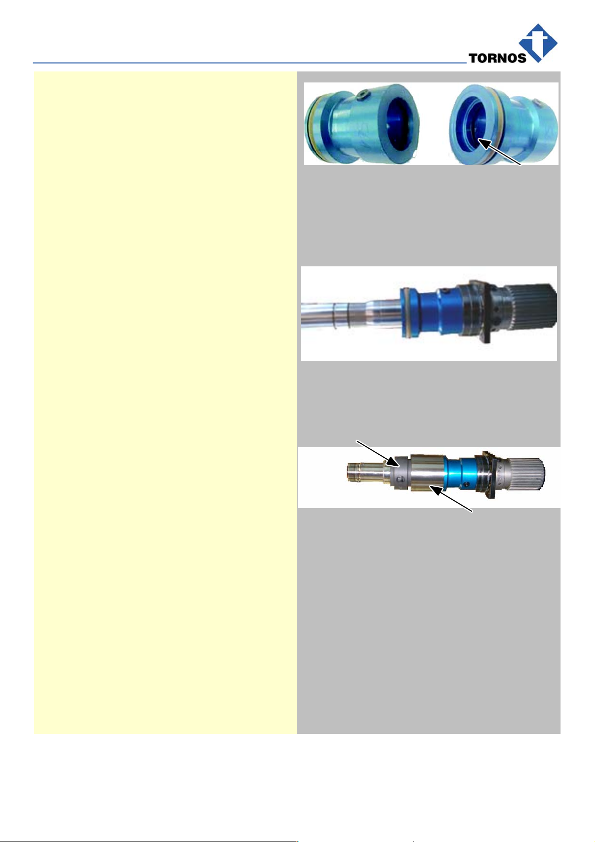
1. Lightly grease inside the case (040).
2. Mount the 2 rear roller bearings (680) in the case
(130) by aligning the marks.
3. Lightly grease the spindle and mount the assem-
bly in the case ”with roller bearings”.
⇒Note :
Case number aligned with the spindle screwed
key.
4. Mount the lock ring (170) with gasket (550).
680
130
TT5501 - DECO 10 Headstock Revision
Chap. 4.2 / 9
TT5501 en - 12/04
5. Insert the guidebush (see figure to right) on the
spindle, lightly grease with the grease Mobil 28
and then mount the primary piston (250).
⇒Note :
To mount the inner gaskets, see the drawing
”Mounting in closed grooves”.
∆Caution !
Pay particular attention to the mounting
direction of the gaskets.
⇒Note :
To facilitate the mounting of the piston, use the
press ”without forcing”.
250
6. Mount the thrust ring (210) on the spindle with the
offset holes against the spindle front side.
7. Mount the gasket (580) on the spindle and then
lightly grease.
⇒Note :
Use the grease Molykote DX.
8. Lightly grease the large inner diameter of the cyl-
inder (240) and mount it on the spindle.
⇒Note :
Use the grease Mobil 28.
9. Degrease the part of the cylinder (220) receiving
the solenoid valve.
10.Insert the ”dry and clean” solenoid valve (230) on
the cylinder.
11. Grease the rear roller bearing of the body and the
case on the spindle.
⇒Note :
Use the grease Molykote DX.
12.Insert the springs after greasing them with the
grease Mobil 28.
13.Lightly grease the front roller bearing of the body
and position the numbers upward.
⇒Note :
Use the grease Kubler NBU15.
14.Grease the screwed key of the spindle.
240
230
15.Mount the front roller bearings (590), align the
marks and orient them to the screwed key side.
16.If necessary, mount with the press and special tool
ref.60.
∆Caution !
Do not strike or hit the roller bearings!

TT5501 - DECO 10 Headstock Revision
Chap. 4.2 / 10 TT5501 en - 12/04
17.Mount the cover (120) ; lightly grease the 2 holes. ⇒Note:
Use the grease Kubler NBU15.
⇒Note :
Offset holes on thread and bore side of the
body.
18.Tighten and apply some locking product to the 4
screws (430). ⇒Note :
Use the locking product Loctite 222.
19.Mount the baffle plate (190) and the flange (200);
push against the front side using the collet.
20.Install the thrust ring (650) in place.
⇒Note :
Gap in the middle on screwed key side of the
spindle. See auxiliary drawing 11A.
21.Alternately tighten the 6 screws (410) diagonally
and torque using the torque wrench.
Position the gap Abetween 2 threads in the
middle of the thrust ring.
⇒Note :
Torque with the torque wrench to the value 1.3
N.
Use some Loctite 222 to lock the screws.
A
22.Lightly grease the rear inner side of the spindle.
Grease the inside and outside of the secondary
piston between the gasket and the threading, and
”hand mount” it in the spindle.
⇒Note:
Use the grease Mobil 28.
23.Grease the spring (270) and mount it in the
spindle. (Mark point on the spring front side
aligned with the refill plug).
24.Grease the case (170) and insert it in the spindle.
B
270
170

TT5501 - DECO 10 Headstock Revision
Chap. 4.2 / 11
TT5501 en - 12/04
25.Place the headstock on the press with the tool ref.
40 to mount the ”Seeger” ring (640), with the gap
of the ring in the middle of the refill plug.
∆Caution !
Install in place without forcing to prevent
damaging the secondary piston’s gaskets.
640
26.Adjust the clearance of the spindle by loosening
the 4 adjusting screws (140) section J-J until at
the stop without forcing by ”alternately tightening
the screws diagonally”.
27.Tap on the body with a nylon mallet to install the
assembly.
28.Tighten 1/4 turn and reloosen 1/8 turn.
29.Tighten the 4 clamping screws with brass wire.
30.Tap on the body with a nylon mallet and check.
∆Attention !
The spindle must turn freely without binding
or wobbling.
31.Mount the tubing (080) and the pivot axis (090)
”lightly greased” section G-G.
Using the nylon mallet, tap softly to not damage
the solenoid valve.
Tighten the sealing plug (100) with its gasket
using the 2 screws (530).
32.Place the thrust tube (260), grease the threads
and tighten it in the headstock. ⇒Note:
Use the grease Mobil 28.

TT5501 - DECO 10 Headstock Revision
Chap. 5. / 12 TT5501 en - 12/04
5. REFILLING THE HEADSTOCK
⇒Note :
Use the oil ISO GV 220
Actions Notes
1. Place a wedge before the headstock to tilt it
slightly so that air can bleed out more easily.
2. The primary piston is positioned completely back-
ward, with the window facing upward.
3. Align the refill plug with one of the primary piston
bleed screws and protect the lathe from the refill
plug with paper to prevent oil from splashing on it.
4. Tighten the large oil gun endpiece in the refill plug
hole. Using the knurled sleeve, loosen the end-
piece one turn minimum.
5. Loosen the primary piston bleed screw and press
on the oil gun until oil flows.
6. Repeat the operation several times until no more
air is bled from the piston.
7. Block the bleed screws, remove the paper, and
tighten the refill plug.
8. Loosen the endpiece.
9. Refill but with the small oil gun endpiece.
10.Remove the endpiece, connect the compressed
air tubing and make back-and-forth movements
so that the gaskets fit into place and then check
operation.
∆Caution !
Check that there are no oil leaks.
Refilling bleed
TT5501 - DECO 10 Headstock Revision
Chap. 7. / 13
TT5501 en - 12/04
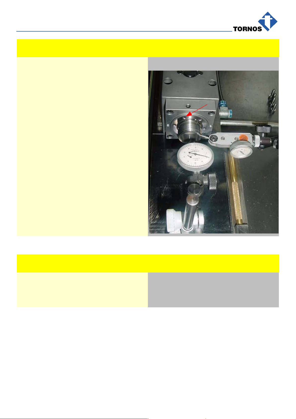
6. CHECKING THE HEADSTOCK
Actions Notes
1. Check concentricity by positioning a comparator
inside the spindle, as well as on the spindle front
side.
⇒Note :
Max. 0.002 mm on the front side.
Max. 0.003 mm inside the spindle.
If necessary, use the 6 adjusting screws A to
adjust the concentricity of the spindle.
2. Insert the collet lightly greased and also check the
concentricity.
⇒Note :
Max. 0.005 mm.
∆Caution !
If the spindle is not within tolerance, dis-
mount the spindle again, check and remount
the assembly.
A
7. BREAKING IN THE HEADSTOCK
Actions Notes
1. See the break-in procedure sheet ⇒Note :
Make a photocopy of the original break-in
sheet.


TT5501 - DECO 10 Headstock Revision
Chap. 9. / 17
TT5501 en - 12/04
9. APPENDIX - DECO 10 BREAK-IN SHEET
1st level 2nd level 3rd level 4th level End of break-in period
Speed 1600 rpm 4000 rpm 8000 rpm 11000 rpm
Time 25 min 120 min 120 min 120 min
Amperage
Front
Bearing
Initial 30
Bearing
Temperature 60
p
90
120
Rear
Bearing
Initial 30
Bearing
Temperature 60
p
90
120
T51st
level 2nd level Initial 4th level Notes
55°T°MAX
50°
45°
40°
35°
30°
25°
20°
min 30 60 90 120 150 180 210 240 270 300 330 360 390
Theoretical Drawing Current: Measured:
NOTES
Information
Maximum break-in temperature : 55°C
If this temperature is attained
program during the break-in period an opening and closing of a collet every 5 seconds.
1. Stop ”break-in”.
2. Wait until the temperature has returned to the ambient temperature.
3. Restart the ”break-in” from the beginning.
4. Fill in a second ”break-in” sheet.
5. If the temperature attains 55°C again, there is an abnormality : dismount the headstock.
Table of contents
Other tornos Industrial Equipment manuals


Popular Industrial Equipment manuals by other brands

DEPURECO
DEPURECO CLEAN OIL Series Use and maintenance manual

Endress+Hauser
Endress+Hauser Kit CSF48 installation instructions

nosstec
nosstec 8344 operating instructions

Jäger
Jäger Z120-H824.12 S11W2V manual

Seco
Seco PACKS EASYSHRINK 20 operating instructions

cytiva
cytiva AKTA readyflux operating instructions


Automatic
Automatic LPE 500 Operator's & installation manual

Siemens
Siemens Simatic S7-400 Getting started

Bosch
Bosch REXROTH mMS 4.0 operating manual

Clemco
Clemco BNP Series owner's manual

Ceriotti
Ceriotti DOMO Assembly instructions

Avid Technology
Avid Technology CNC Rotary Axis Installation & Calibration Manual