GOALRILLA YARD GUARD B2800W-2 User manual

2017 Escalade Sports
© ®
Escalade®Sports products may be manufactured and/or licensed under the following patents:
6419596, 6179733, 5919102, 5071120, 4798381, 4424968, D326128, 7244046
Additional patents may be pending. One or more of the listed patents and/or pending patents may cover specific product.
1. Read this manual carefully before starting assembly. Read each step completely before beginning
each step.
2. Some smaller parts may be shipped inside larger parts. Check inside all parts and cartons
before assembling or ordering parts.
3. To make assembly of your Yard Guard easier, c h eck all cartons for kits.
All hardware may not be located in one kit.
4. Do not tighten hardware until instructed to do so. If hardware is tightened too soon, mounting holes
may not align and parts may not easily fit together. Leave locknuts slightly loose until you are instructed to
tighten them. You will need a 5/8” wrench, two 1/2” wrenches and a
O W N E R ' S M A N U A L
MODEL NO.
B2B2 800W-2
Yard Guard
Contact Escalade® Sports customer service department at:
Phone: 1-888-USA-GOAL Toll – Free !
Fax: 1-866-873-3536 Toll – Free !
E-mail: basketball@escaladesports.com
Mailing Address (correspondence only):
Escalade Sports
PO Box 889
Evansville, IN 47706
Please visit our World Wide Web site at: www.goalrilla.com
ON-LINE TROUBLE SHOOTING TECHNICAL ASSISTANCE
ON-LINE PARTS REQUESTS FREQUENTLY ASKED QUESTIONS
ADDITIONAL ESCALADE® SPORTS PRODUCT INFORMATION
2L-7616-01
Please Do Not Return This Product To The Store!
5.
Save these instructions and your proof of purchase (receipt) in the event that the manufacturer
has to be contacted for replacement parts.

4L-8156-00
WARNING
!
ŸCHECK PRODUCT FOR DAMAGE AND REPAIR BEFORE EACH USE
(LOOSE HARDWARE, RUST, TORN NETS, INSTABILITY) NEVER PLAY
ON DAMAGED EQUIPMENT!
ŸDO NOT CLIMB OR JUMP ON PRODUCT.
ŸDURING PLAY DO NO WEAR JEWELRY (WATCHES, RINGS, ECT.)
OBJECTS CAN ENTANGLE IN NET.
ŸPUT PRODUCT IN STORAGE POSITION WHEN NOT IN USE, DURING
STORMS, AND DURING AGGRESSIVE PLAY.
NOTE: ALWAYS place the Yard Guard into the Storage position when not in use,
especially during bad weather. Net sleeves can fill and hold water causing
damage.
INSTALLING THE YARD GUARD
-Two adults are recommended for the Yard Guard installation.
Please Read Manual for Tips that will Greatly Reduce assembly Time!
-Remove all pole pads before installation. The lower pad of the Goalrilla pole pads are not compatible with the
Yard Guard, you will need to replace with the provided lower pad and then place your existing Goalrilla pad on top as
normal.
- A set of two U-bolts is required for installation.
Based upon pole size, use either the 5 x 5, 5.5 x 5.5, 6 x 6, or 6 x 8 labeled sets. These sets should include 2 different
size U-bolts.
NOT TO SCALE
#3
#15
Lower
U bolt
Upper
U bolt
2

NOTE: Two brackets (#1 & #2) are required. Bracket #1with three holes goes on top of bracket #2.
#1
Protective Surface on this
side will face the back of
the pole.
#2
#7
Washers
#7
Washers
INSERTING #6 POLES TO YARD GUARD BRACKETS
#2
#2
#6
#6
YARD GUARD BRACKET
Detail A
A. Before assembly peel and stick washers to Brackets
#1 & #2 as shown in Detail A.
Detail B
B. To insert tube #6 in brackets slide down and
rotate tube into position until the holes in the
bracket, washer and the tube line up. See
Detail B-D.
Hole in tube
Hole in tube lines up with
washers and bracket holes.
NOTE: When inserting tube into bracket it
will be a tight fit, this is normal and will
provide stability to the assembly.
Detail C
Detail D
NOTE: DO NOT ATTEMPT TO JUST PUSH AND
SLIDE INTO PLACE, THIS WILL BE EXTREMELY
DIFFICULT AND COULD DAMAGE PRODUCT.
FOLLOW INSTRUCTIONS BELOW ON HOW TO
SLIDE AND ROTATE INTO PLACE.
3

Protective Surface on
brackets goes facing
the pole to prevent
damaging the pole.
Back of Pole
1. Taking the longer U-bolt #3 slide it over the pole as shown
below, . Please be careful not to scratch the paint Detail 1
from your system, packaging foam can help with this.
Detail 2
Detail 1
2. Using the provided #7 washers with double stick tape. Stick
them on the inside of the lower brackets as shown in previous
page. Proceed to then slide the brackets over the U-bolt #3
and complete the rest of the lower assembly, see . Do Detail 1
Not Tighten Nut onto U-bolt yet, use only to keep other items
in place.
3. To attach the brackets to each other, pull them together until
one of the three holes on top bracket #1 align with the single
hole in the bottom bracket #2. shows the location for Detail 2
a 5 x 5, 5.5 x 5.5, 6 x 6, and 6 x 8 pole. Insert screw #9 and
tighten nut #10 to the bottom. After completing the assembly
should be just above the systems triangular gussets. At this
point, tighten U-bolt nuts #5 secure so that front to back
wobble is eliminated but rods and connectors can still pivot.
Figure 1
FRONT
OF
POLE
7
2
3
5
8
9
10
6
12
11
6
12
11
6
1
5”
5.5” &
6x8”
6”
4
Two 7/16” Wrenches and one 9/16” Wrench will be required for the following steps.
4. Slide #11 Middle, #12 End & #6 poles together as shown in
Figure 1.
4

13
6
Detail 3
5. Slide Right Yard Guard net (#13) onto Steel Tube assembly as shown in Detail 3. Repeat for Left Yard
Guard Net #14 with Brand and Warning Label. No screws are required for assembly.
Figure 2
Left Side
Right Side
BEFORE GOING TO THE NEXT PAGE DETERMINE WHICH BASKETBALL SYSTEM YOU HAVE. IF
YOU HAVE A “FT” SERIES BASKETBALL GOAL (for example B3015,B3016 or B3017) SKIP TO PAGE 7.
FOR ANY OTHER GOALRILLA BASKETBALL SYSTEM CONTINUE TO PAGE 6.
NOTE: To find your model number refer to your Basketball systems owner’s manual. Alternatively,
the Goalrilla basketball units will have a sticker on the back of the pole with the model
number (starts with the letter B).
5

8. Slide Fiberglass Rods #17 together and insert into Sleeve #18. Next insert one end of the fiberglass rod #17 and sleeve
#18 into the triangular pocket on the FRONT upper outside corners of the net. The rod will then remain on the front of
the net until it reaches the second diagonal square from the lower inside corner as shown in Detail 6. Push it though this
hole and down into the fiberglass rod pivot connector. Then carefully take the fiberglass tube sleeve and slide it over the
pivot connector as well. Do this for both sides. Make sure to slide part #17 (Rod Sleeve) over pivot connector as well. At
this point the Yard Guard should be free standing.
Detail 6
Second
diagonal
square
Detail 7
Detail 6
17
17
18
*Rim & Net not shown
for clarity.
For systems with a hoop light only.
6. Using a ladder take the upper pole bracket #16 with Protective
surface facing the pole, slide the shorter U-bolt #15 through
bracket to attach the Nets as shown in . Attach nuts so Detail 4
that the bracket may still move up and down. Carefully position
assembly so that net is fairly tight and most of the slack is
removed. At this point tighten nuts snug so that the U-bolt and
bracket cannot move. DO NOT CRUSH the grommet in the net.
7. If using a hoop light remove the LOWER nuts as shown in
and attach net to lower U bolt on Light Bracket as Detail 5
instructed on Step 6. Detail 4
Detail 5
For systems with a hoop light only.
Figure 3
45
14
16
15
13
4L-8156-00
WARNING
!
13
14
Warning label
Logo
Protective Surface
6
SKIP TO PAGE 11 TO CONTINUE THE INSTALLATION

5/16-18 X 1 1/4" BOLT (ZINC)
1B-7168-00
5/16-18 LOCKNUT
2B-6009-02
3/8-16 X 1” NYLON BOLT
1B-7169-00
Tower
2S-9419-00
Bracket
4A-8245-00
QTY.2
QTY.6
QTY. 4
QTY.2 QTY.1
7
PARTS TO ATTACH TO “FT” SERIES MODELS
HARDWARE TO ATTACH TO “FT” SERIES MODELS
21
22
24 25
23

8
Brackets to hold the yard Guard net will
be installed on the to the upper poles as
shown
OVERVIEW
STEP 1
Center the bracket from front to back on
each pole, then using a 5/8” wrench
carefully screw the Nylon Bolts (#23) in
but leave the bracket loose enough so it
can be slipped up and down.
Set the Brackets (#21) on top of the
upper posts making sure the two
Centering Indentations on each bracket
are to the inside.
HARDWARE NEEDED (ACTUAL SIZE)
23
3/8-16 X 1” NYLON BOLT
1B-7169-00
QTY.6
INSTALLATION FOR MODELS: B3015, B3016 & B3017 (FT SERIES)
STEP 2
INSTALLATION
LOCATION
8
21
23
Centering
Indentations
21
23
23

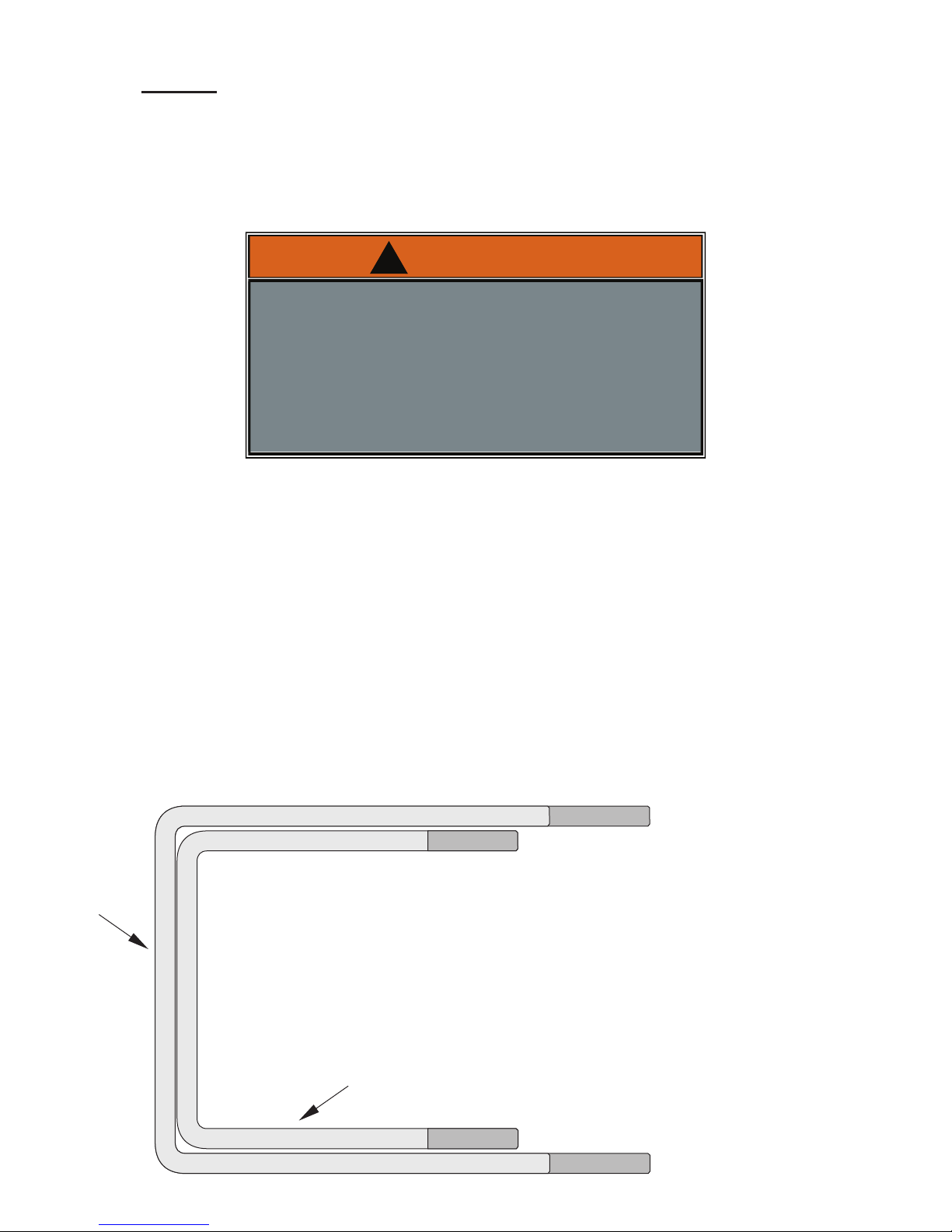
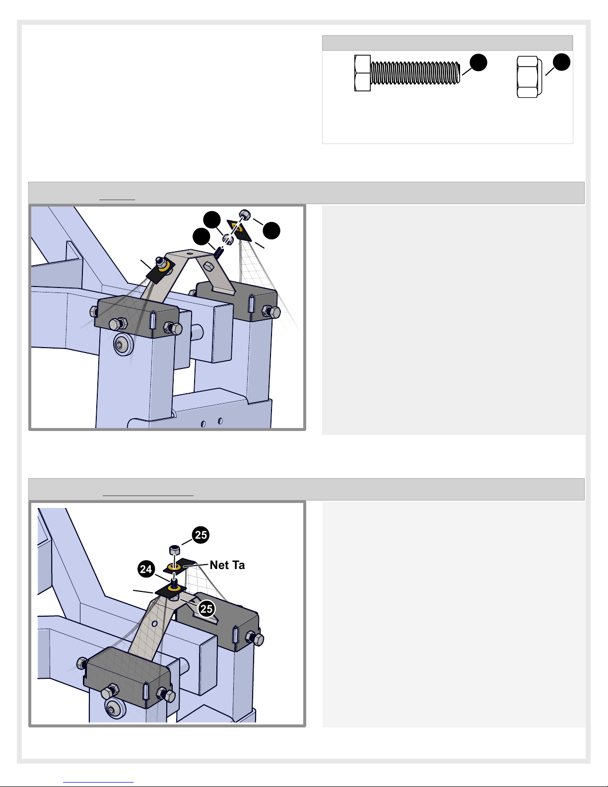
The sheet metal Tower (#22) can flex to get
wider or narrower, on units with a 72” or 60”
backboard the Tower will need to be flexed out
to fit the brackets. On units with a 54”
backboard the Tower may need to be flexed in.
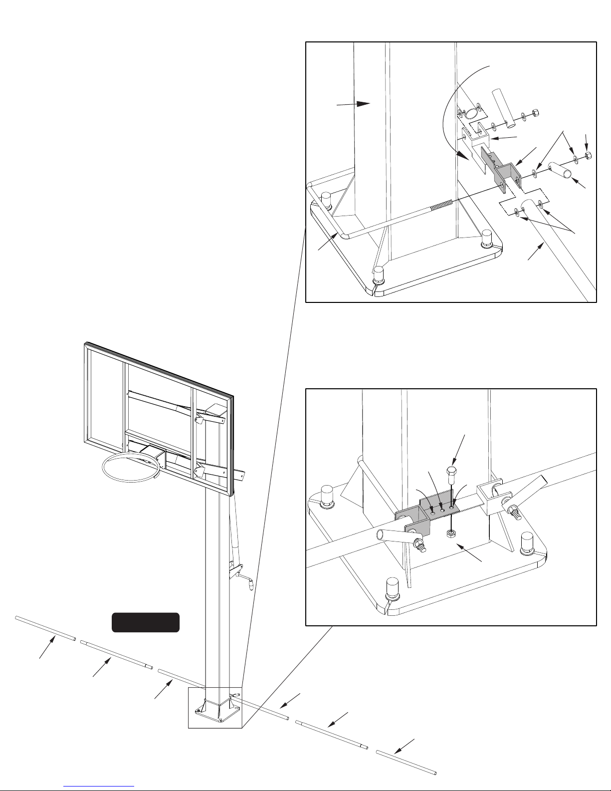
Make sure the bracket is centered from front to
back, then tighten front & back Nylon bolts.
Lastly, tighten middle bolt until the brackets
are completely secure. See note below.
TOWER
STEP 3
STEP 4
OR
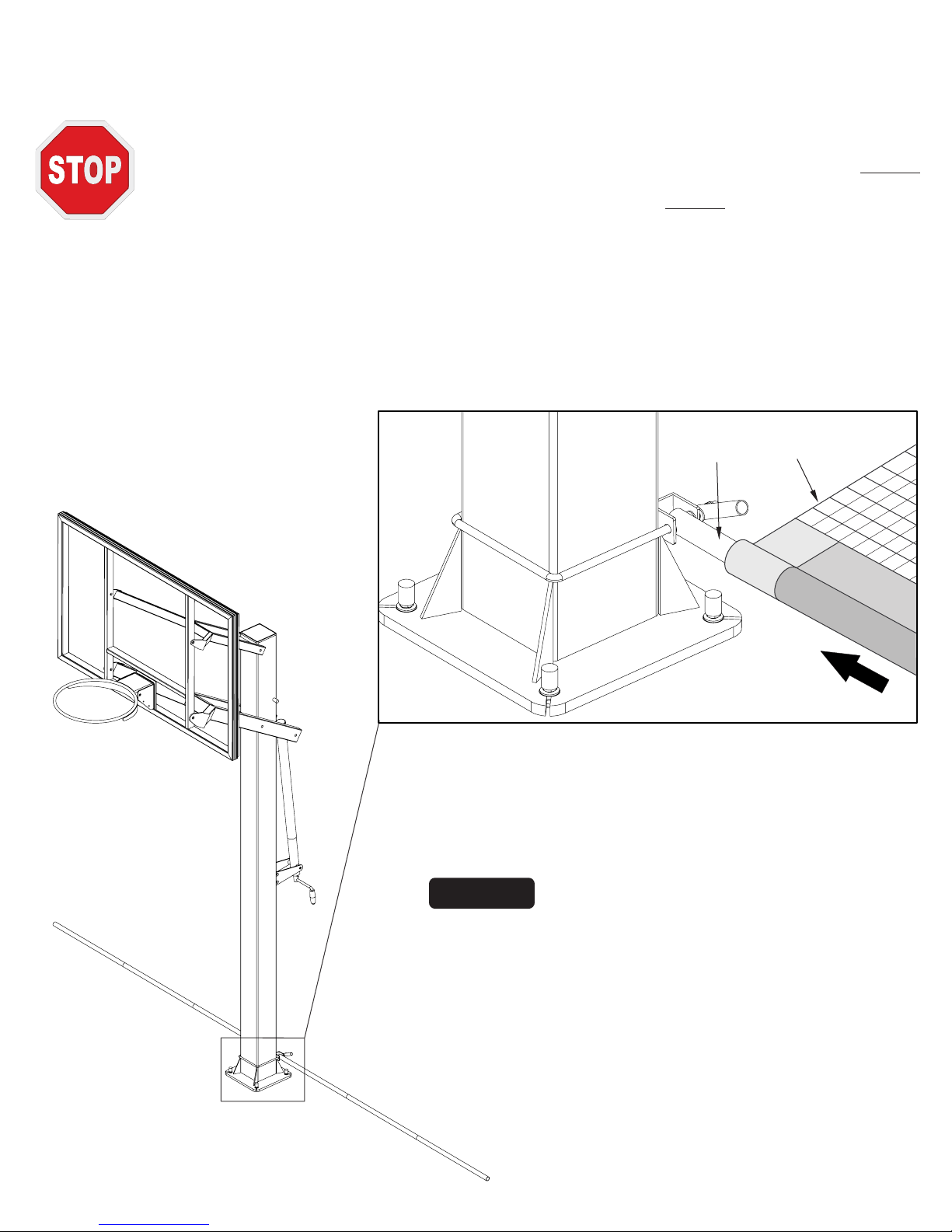
Insert Tower (#22) into the opening of the
Bracket (#21). On one side, line up the two
holes in the Tower to the two centering
indentations in the bracket, then do the same
for the other side until both sides of the tower
are in the bracket.
NOTE: TIGHTEN BOLTS UNTIL SECURE, BUT
DO NOT OVER TIGHTEN!! THIS COULD
CAUSE YOUR POST BRACKET TO DEFORM.
If this happens, loosen bolts until bracket
regains its shape and tighten back up slowly
until it is firmly on pole.
9
NOTE: Tower will deform permanently.
Assembly tip: Lifting each bracket up
separately and then sliding it back into place
can assist in this process.
NOTE: When tightened the bolts on model FT
72 will stick out more than on smaller units.
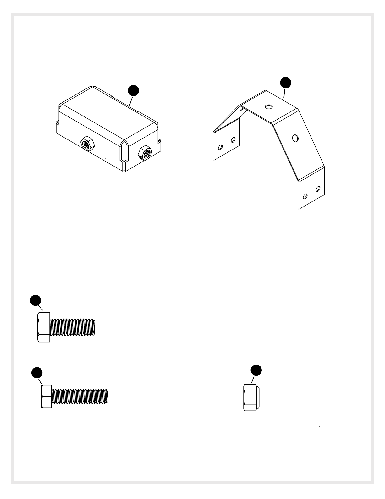
22
22
22
21
21
NOTE: Inside the bracket there
will be “centering indentations”
that will need to be lined up with
the holes in the Tower for the next
step.
Inner
Centering
Indentations
21
Back
Bolt
Front
Bolt
Middle
Bolt

Insert a bolt (#24) through the holes in each
side of the tower followed by one nut (#25)
and tighten until secure using a 1/2” Wrench.
Net tabs will go on each bolt (#24) as shown,
add a locknut (#25) and tighten to secure
each net tab. DO NOT CRUSH GROMMETS!
Insert one bolt (#24) through the middle hole of
the tower followed by one nut (#25) and tighten
until secure using a 1/2” Wrench.
Both Net tabs will go on the bolt (#24) as shown,
add a locknut (#25) and tighten to secure the net
tabs. DO NOT CRUSH GROMMETS!
5/16-18 LOCKNUT
2B-6009-02
QTY. 4
24
25
25
Net Tab
5/16-18 X 1 1/4" BOLT (ZINC)
1B-7168-00
QTY. 2
HARDWARE NEEDED (ACTUAL SIZE)
NOTE: If nets sit too high or low, the other
configuration above may be used. Using the
one bolt configuration will raise the net, using
the two bolt configuration will lower it.
NOTE: If you have a FT72 (72”backboard)
continue with “Step for FT72”, on any other
unit skip to step “FT54 & FT60”.
NOTE: If nets sit too high or low, the other
configuration below may be used. Using the
one bolt configuration will raise the net, using
the two bolt configuration will lower it.
Net Tab
25
25
24
24 25
Continue to next page for the remainder
of the assembly.
STEP for FT72
STEP for FT54 & FT60
Continue to next page for the remainder
of the assembly.
Net
Tab
Net
Tab
10

9. There are 5 straps #19 used to secure the Yard Guard to
your pole as shown in . Center the space between Detail 7
the two clips on the back of the pole. Pull each Velcro
side towards the front of the pole, going the inner through
most net squares and secure at the front. Starting
approximately 16” From the base, continue this process at
about 12” increments, until all 5 are used. Refer to Detail
8 - Detail 10.
FRONT VIEW
Detail 8
Detail 11
FRONT
OF POLE
10. The lower pad of the Goalrilla pole pads are not
compatible with the Yard Guard, you will need to
replace with the provided lower pad #20 and then
place your existing Goalrilla pad on top as normal.
(Straps can go through inner most net squares)
Your Yard Guard is now complete! It is in the deployed
position. To store it, during non-play, bad weather, of
rough play follow the steps in the next page.
Detail 7
Detail 9
BACK OF POLE Detail 10
#20
FRONT OF POLE
FRONT OF POLE
19
FRONT OF POLE
BACK OF POLE
11

1. First, make sure all male clips have been disconnected from their
corresponding clips. Carefully lift the bottom tube of the Yard Guard
upwards and toward the net. Gather the excess netting to the pole
with one hand while using the other to grab the top storage Strap
with the Plastic Clip. Simply bring the Strap with male Plastic
Clip around the front and outside of the Yard Guard and connect the
female Clip, located on the back on the pole pad See Figure 4-6, Side
View and Back View. Connect the other four straps in the same
manner. Repeat this same procedure on the other side.
Storage instructions
4L-8156-00
WARNING
!
NOTE: Straps will be tight. This will help to secure
and Protect the Yard Guard.
Figure 4
Figure 5
Figure 6
4L-8156-00
WARNING
!
4L-8156-00
WARNING
!
4L-8156-00
WARNING
!
Detail 12
Female
Plastic
Clip
Plastic
Clip
Male
Detail 13
Strap with
Plastic
Clips
Detail 14
FRONT OF POLEFRONT OF POLE
12

18
17
45
14
16
15
13
FRONT
OF
POLE
7
2
3
5
8
6
1
19
14
13
12
11
6
12
11
6
4
Back of Pole
9
10
4L-8156-00
WARNING
!
20
*Rim not shown
for clarity.
13
*PARTS LIST IS LOCATED ON
THE NEXT PAGE

4A-8119-00
4A-8120-00
2B-6787-00
2B-6785-00
8S-7934-00
2B-6786-00
8S-7700-00
1B-7048-00
2B-6814-00
8S-7935-00
8S-7936-00
4A-8121-00
4A-8122-00
4A-7934-00
4A-7930-00
4A-7932-00
4A-7929-00
4A-7935-00
4A-8245-00
2S-9419-00
1B-7169-00
1B-7168-00
2B-6009-02
1B-7049-00
1B-7050-00
1B-7051-00
1B-7052-00
1B-7053-00
1B-7054-00
1B-7055-00
1B-7056-00
2L-7616-01
Key# Part # Description Qty.
1
2
3
4
5
6
7
8
9
10
11
12
13
14
15
16
17
18
19
20
21
22
23
24
25
Lower 3 hole bracket
Lower 1 hole bracket
See U bolt section below
3/8” Washer no tape
3/8” Nuts for U bolts
Inner Tube (with hole)
3/8” Washer w/ double sided tape
Fiber Glass rod Pivot Tube
1/4” Bolt
1/4” Lock Nut
Center Tube
Outer Tube
Right side net
Left side net
See U bolt Section below
Upper Bracket (with slots)
Fiberglass rod set
Fiberglass rod covers
Universal Straps to hold net
Pole Pad Segment
Bracket (FT series)
Tower (FT series)
Nylon Bolt (FT series)
5/16”-18 X 1 1/4” Bolt-Zinc (FT series)
5/16”-18 Locknut (FT series)
4.75X6” U bolt (5X5 Pole)
4.75X7.5” U bolt (5X5 Pole)
5.5X6.75 U bolt (5.5 X 5.5 Pole)
5.5X8.25 U bolt (5.5 X 5.5 Pole)
6X7.25 U bolt (6X6 Pole)
6X 8.75 U bolt (6X6 Pole)
6X9.25 U bolt (6X8 Pole)
6X10.75 U bolt (6X8 Pole)
1
1
8
4
2
4
2
1
1
2
2
1
1
1
2
2
5
1
2
1
6
2
4
1
1
1
1
1
1
1
1
U BOLTS:
14
PARTS LIST FOR THE GOALRILLA YARD GUARD B2800-2

®
This consumer warranty extends to the original consumer purchase of any Escalade Sports Product (hereinafter referred to as the “Product”).
®
WARRANTY COVERAGE: Escalade Sports warrants to the original Consumer Purchaser that any Product of its manufacture is free
from defects in material and workmanship. THIS WARRANTY IS VOID IF THE PRODUCT HAS BEEN DAMAGED BY ACCIDENT,
UNREASONABLE USE, NEGLIGENCE, IMPROPER SERVICE, FAILURE TO FOLLOW INSTRUCTIONS PROVIDED WITH THE
PRODUCT OR OTHER CAUSES NOT ARISING OUT OF DEFECTS IN MATERIAL OR WORKMANSHIP.
®
Subject to proper installation and normal Residential use, Escalade Sports warrants, subject to the limitations below, to the original retail
®
purchaser all structural components (not accessories) of the Goaliath System to be free of defects in material and workmanship for a period
of One (1) year from the original purchase.
®
Merchandise must be shipped prepaid with a copy of proof of purchase to Escalade Sports factory for examination to determine if the
basketball system needs to be repaired or replaced. Any labor costs, travel expenses and any other changes involved in the removal,
®
installation or replacement of the defective/repaired parts from/to your Goaliath System will be the purchaser's responsibility. Shipping
®
charges for replaced or warranted merchandise sent back to the customer from Escalade Sports factory must be prepaid by the customer
in advance. If not, the replacement shipment will be sent out collect.
®
Escalade Sports reserves the right to examine photographs or physical evidence of merchandise claimed to be defective, and to
recover said merchandise, prior to authorization of warranty claims. A “Returned Goods Authorization” number may be required,
please call for details prior to the return of any photographs or merchandise.
This limited 1 year warranty is expressly in lieu of all warranties, expressed or implied, including warranties of merchantability or fitness for use.
®
Escalade Sports does not assume or authorize any person or representative to assume for us, any other liability in connection with the sale
of our products.
® ®
The remedy of repair or replacement stated above is Escalade Sports exclusive remedy. Escalade Sports will not be liable for any other
®
damages or expenses which may incur, including but not limited to incidental or consequential damages. Escalade Sports assumes
®
no other obligations or liability on the part of the purchaser, and Escalade Sports neither assumes nor authorizes any other person
to assume for it any other liability in connection with the goods sold.
®
This warranty shall not apply in any manner to parts or accessories not manufactured by Escalade Sports.
NOT COVERED BY THIS WARRANTY
• Merchandise not intended to be in places of public assembly, such as, but not limited to, schools, parks, public or private
Recreational Facilities. .
• Any merchandise subjected to Non-residential abuse, negligence, improper installation, vandalism, acts of God, alteration of product, or
®
any other events beyond the control of Escalade Sports.
• Paint or rusted parts. If rust should appear, remove loose paint, sand lightly, primer and paint with exterior flat matte finish
Enamel Paint.
• HANGING ON RIM WILL VOID THE WARRANTY: Rims are not warranted for any defects other than workmanship. Torn.
back plates, damaged springs, bent rings, damaged eyebolts, and torn or distorted rim supports result from hanging on the
rim and are not warranted.
®
• Shipping charges both ways. Note: Any merchandise shipped to Escalade Sports collect will be refused.
• Dealer service charges, labor charges and travel expenses associated with replacement of repair of warranty item.
• “Yard Guard™” is warranted for one (1) year. Warranty is void if “Yard Guard™ is not used for it's
Intended use.
WARRANTY DISCLAIMERS: ANY IMPLIED WARRANTIES ARISING OUT OF THIS SALE, INCLUDING BUT NOT LIMITED TO THE
®
IMPLIED WARRANTIES OF MERCHANTABILITY AND FITNESS FOR A PARTICULAR PURPOSE, ARE LIMITED IN DURATION. ESCALADE
SPORTS SHALL NOT BE LIABLE FOR LOSS OF USE OF THE PRODUCT OR OTHER CONSEQUENTIAL OR INCIDENTAL COSTS.
EXPENSES OR DAMAGES INCURRED BY THE CONSUMER OF ANY OTHER USE.
Some states do not allow the exclusion or limitation of implied warranties or consequential or incidental damages, so the above limitations or
exclusions may not apply to you. LEGAL REMEDIES: This warranty gives you specific legal rights, and you may also have other rights which may
vary from state to state.
WARRANTY GUIDELINES IS REQUIRED FOR ALL WARRANTY CLAIMS
1. Proof of Purchase (original retail purchaser) is required for all warranty claims.
®
2. Call or write Escalade Sports to receive a Return Authorization # and determine specific needs.
Phone: 1-888-USA-GOAL / Warranty Dept.
® ®
Or Write Escalade Sports at: Escalade Sports - P.O. Box 889, Evansville, IN 47706 - Attn: Warranty Dept.
Or E-mail us at: [email protected]
LIMITED 1 YEAR WARRANTY
15
Table of contents
Other GOALRILLA Accessories manuals
Popular Accessories manuals by other brands

Baumer
Baumer O200 quick start guide

Aroma360
Aroma360 360 Mini user manual

Becker
Becker CentronicPLUS SC811 PLUS Assembly and operating instructions

Cooper Lighting
Cooper Lighting METALUX SNLED installation instructions

Airthereal
Airthereal LF500M user manual

DigiDesign
DigiDesign Mbox Getting started guide