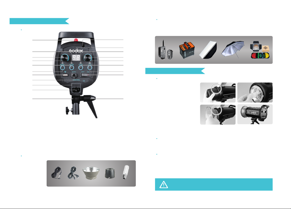
Separately Sold Accessories
The product can be used in combination with the following accessories sold
separately, so as to achieve best photography effects:
Godox FT series remote control, Power Inverter, Softbox, Photographic Umbrella,
Light Stand, Barndoor, Snoot, etc
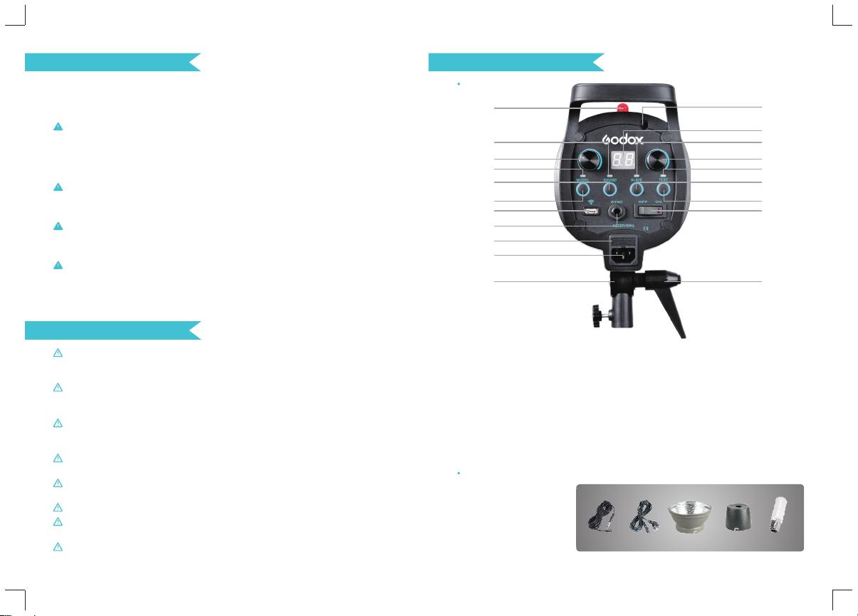
OPERATIONS
Flash Preparation
Power Connection
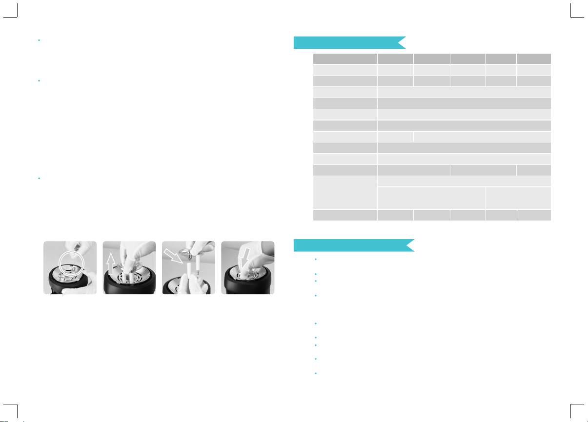
1. Take down the lamp
cover. Install the modeling
lamp and put on the glass
protection cover and the
standard reflector.
(To uninstall the standard
reflector, press the release
button on the flash head
and turn the standard
reflector counter-clockwise
to take it out, as illustrated
in the picture.)
2. Attach the flash unit onto
an appropriate light stand. Adjust the mounting bracket (18) for a good angle and
make sure it is tightened and fixed. Use the direction adjusting handle (20) to
adjust the flash to a desired direction. Umbrella input (19) is for different photo
umbrellas to put in.
Use the power cord to connect the flash to an AC power source and turn on the
power switch (3). The lamp on the power switch turns on, indicating it’s connected.
Modeling Lamp Button (6) controls the modeling lamp status: when modeling
lamp indicator lights up, modeling lamp is on; if not, modeling lamp is off.
Modeling lamp output controller (4) is used for adjusting the power output level of
modeling lamp. Modeling lamp will be off automatically after lighting for 2 hours,
avoiding overheat due to long-time lighting when the user is not nearby.
Modeling Lamp
When there is flammable accessory on the flash unit, do not keep the
modeling lamp on for a long time. It is recommended to cool it down
for one minute after 10 minutes' working.
Power Output Control
Flash output controller (5) decides different power output, satisfying light
requirements in different environment. The power is adjustable freely from 5.0 to
8.0 which will be accordingly shown on the digital display (10). "OF" on the
display indicates that the flash triggering function is turned off. It can
automatically discharge power when the flash output is adjusted from high to low.
Test Button
To fire the flash without taking a picture, press the test button (9). It can also help
adjust the flash brightness when combined with the flash output controller (5).
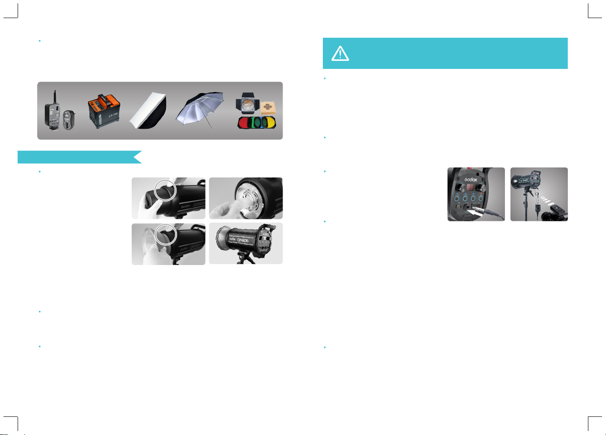
Sync Triggering
The sync cord jack (2) is a Φ6.35mm
plug. Insert a trigger plug here and
the flash will be fired synchronously
with the camera shutter.
Slave Trigger Model
Three slave triggering models are
available and can be set by pressing Slave Model Button (8).
◆No optical control: The slave triggering indicator (13) is off, indicating the slave
triggering function is shut down.
◆One fire model: The slave triggering indicator (13) glows blue, indicating the
flash will fire synchronously when receiving one external flash. In this model, the
flash can function as an auxiliary lamp, offering various effects of light and
shadow.
◆Anti-preflash model: The slave triggering indicator (13) glows red, indicating the
flash will receive two external flashes within 2 seconds and will fire synchronously
when receiving the second flash. In this model, the flash can function as an
auxiliary lamp, applicable to TTL system. With this anti-preflash function, the flash
can synchronize with cameras having a one-preflash firing system.
Buzz Function
The sound button (7) is used for deciding whether there is sound reminder for
ready flash after recharging. When the buzz indicator (12) is on, the buzz function
is working; when it is off, the buzz function is not working. A “BI” sound will be
heard when it’s fully charged.
- 12 -- 11 -