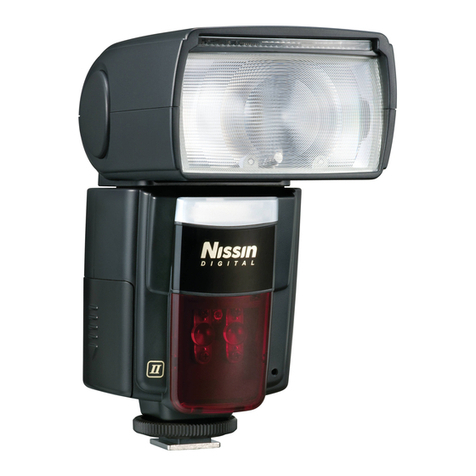
Studio Flash Trigger
AT Series
I n s t r u c t i o n M a n u a l
Instructions for Use
Function Introduction
Connection
Operation
Technical Data
Attentions
Maintenance
Contents
Foreword
Thank you for purchasing AT Series Studio Flash Trigger.
The device is composed of two parts, namely signal transmitter
and receiver. It is a control discreteness for camera to trigger
studio flashlight synchronously.
Foreword
Warning
Names of Parts
Body
Accessories
Battery
Channel Settings
Names of Parts
Body
(1) AC Output Pin
(2) AC Input Jack
(3)Trigger Output Pin
(4) Channel Code Switch
(subject to different model,
unavailable for AT-01)
(5) Receiving Signal LED Indicator
(6) Power LED Indicator
Receiver
(7) Hot Shoe Fitting
(8) PC Cord Jack
(9) Transmitting Signal
LED Indicator
(10) Test Button
(11) Channel Code Switch
(subject to different model,
unavailable for AT-01)
Transmitter
Accessories
1. Convert Adapter
2. Instruction Manual
The transmitter is equipped with a 23A 12V lithium-ion battery
which can normally be used for over ten thousand times.
To replace the battery, loosen the screw on the back to open.
The screw may be covered by a QC sticker.
Battery
Channel Settings
There are16 channels in this device. Set the transmitter and
receiver on the same channel before use. Check the table
for channel setting as below:
1 2 3 4 5 6 7 8 9 10
0 1 0 1 0 1 0 1 0 1 0 1 0 1 0 1
0 0 1 1 0 0 1 1 0 0 1 1 0 0 1 1
0 0 0 0 1 1 1 1 0 0 0 0 1 1 1 1
0 0 0 0 0 0 0 0 1 1 1 1 1 1 1 1
11 12 13 14 15 16
S1
S2
S3
S4
Channel
AT Series Studio Flash Trigger is based on a wireless
remote system. The transmitter is equipped with an
advanced electric circuit. It has sleepy function, thus very
low power consumption is needed. The receiver is used
with alternating current, and it achieves quick response
under the advanced MCU control. It can meet the need
of sync flash for any different shutter camera.
Instructions for Use
Function Introduction
Connection
1.Unplug the AC Power Pin from
the strobe and insert it into the
AC Input Jack (2).
2.Insert AC Output Pin (1) into the
Power Input Jack of the strobe.
3.Insert the Trigger Output (3) into
the sych cord Jack of the strobe.
4.Connect the AC power supply
and the power LED indicator
(6) will turn green.
1.Set the transmitter and receiver
in the same channel position.
2.Press down the Testing Button
(10), and the Trigger Signal
LED Indicator (5) will turn red
and simultaneously the strobe
will flash to work.
3.Insert the Hot Shoe (7) into the
camera hot shoe mount for
normal use.
(It varies in cameras)
4.If the camera has no hot shoe
jack, insert one end of the
PC Cord into PC Cord Jack
(8)and the other end into the
synchronous jack of the camera.
Operation
Technical Data
AT-01 AT-02 AT-04 AT-16
1 2 4 16
433MHz wireless remote system
12V 23A lithium-ion battery
AC:100-240V; 50/60Hz
Φ6.35mm / Φ3.5mm
≤30 m (Open space)
≤20 m (Open space)
1/200 sec
60*42*30mm/40g
72*56*37mm/90g
Model
Channel
Transmit frequency
Transmitter power
Receiver power
PC cord jack
Outdoor operation distance
Indoor operation distance
Sync speed
Transmitter Size &Weight
Receiver Size & Weight
Attentions
Unable to trigger flash or camera shutter. Make sure the
transmitter and receiver are set to the same channel,
and the PC cord or the hot shoe mount is completely
connected.
Maintenance
Avoid falling
The device may malfunction after strong shocks or under
excess stress.
Signal disturbance or shooting interference. Change
different channel on the device.
Operating distance limited or flash missing. Check if the
battery is exhausted. Try to change the battery.
Keep away from strong magnetic field. The strong static
or magnetic field produced by devices such as radio
transmitter leads to malfunction.
1
Avoid sudden temperature changes
such as the circumstance when taking the remote control
out of a building with higher temperature to outside in
winter. This may lead to condensation of moisture.
Please put the remote control in handbag or plastic
bag to prevent sudden temperature changes.
Keep dry
The production isn't water-proof. It will lead to malfunction
if soaked in water or exposed to high humidity, which
cause malfunction and rust, corrosion.
Made In China
1
2
3 4 56
7
8
10
9
11
Warning
Do not disassemble. Should repairs become necessary, this
product must be sent to an authorized maintenance center.
Always keep this product dry. Do not use in rain or in damp
conditions.
Keep out of reach of children.
Do not use the flash unit in the presence of flammable gas.
In certain circumstance, please pay attention to the relevant
warnings.
Do not leave or store the product if the ambient temperature
reads over 50℃.
Turn off the flash trigger immediately in the event of malfunction.
Observe precautions when handling batteries
- Use only batteries listed in this manual. Do not use old and
new batteries or batteries of different types at the same time.
- Read and follow all warnings and instructions provided by the
manufacturer.
- Batteries cannot be short-circuited or disassembled.
- Do not put batteries into a fire or apply direct heat to them.
- Do not attempt to insert batteries upside down or backwards.
- Batteries are prone to leakage when fully discharged. To avoid
damage to the product, be sure to remove batteries when the
product is not used for a long time or when batteries run out of
charge.
- Should liquid from the batteries come into contact with skin or
clothing, rinse immediately with fresh water.
