闪光模式:M 手动闪光
闪光模式:TTL自动闪光模式
离机使用时,建议通过自定义功能使“自动关闭电源”无
效。
“从属单元自动关闭电源计时器”出厂默认设置为60分
钟,也可自定义选择30分钟。
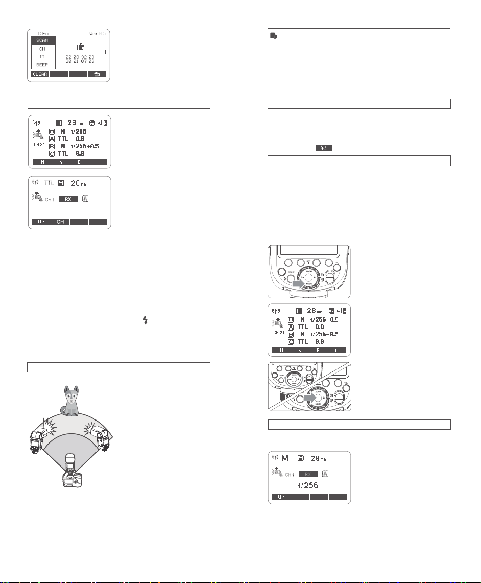
C.Fn
C.Fn
该闪光灯有TTL自动闪光,M手动闪光,Multi频闪闪光三种
模 式 。在 TTL模式下,相机的测光系统会侦查从主体反射回
来的闪光照明,从而自动调节闪光输出量,使主体和背景得
到均衡曝光。支持曝光补偿、高速同步、第二帘快门同步等
功能。
*按下<MODE>模式选择按钮,三种闪光模式将会依次出现
在液晶屏上。
TTL模式
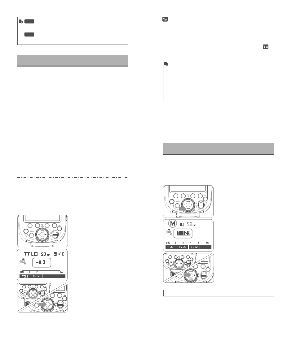
通过按<MODE>模式选择按钮,将闪光灯设置为<TTL>, 可
以使闪光灯进入TTL模式。
●
半按相机快门按钮进行对焦,光圈值和有效闪光范围将会
显示在显示屏上。
●
在快门释放前的瞬间进行一次预闪,闪光灯接收相机信息
进行主闪光。
第二帘快门同步
使用慢速快门,您可以在被摄体后创建一条光线轨迹。在快
门关闭前的瞬间闪光灯闪光。
高速同步
使用高速同步(FP闪光),您可以在所有的快门速度下同步
使用闪光灯。高速同步闪光在使用光圈优先对人像进行填
充闪光时特别方便。
闪光曝光补偿
该闪光灯可以在±3档间以1/3档为增量调节闪光曝光补偿。
由于环境的需求而需要微调TTL系统时,这个功能非常有用。
设置闪光曝光补偿:
1
2
3
按下<+/->按钮,令屏幕显
示闪光曝光量,并且闪光
曝光补偿量被突出显示
按下设置按钮,确定闪光
曝光补偿。
设 置 闪 光 曝 光 补 偿 量 。
●
转动调节旋钮设置曝光
补偿量。
●
"0.3"表示1/3档,"0.7"
表示2/3档。
●
要取消闪光曝光补偿,
将闪光曝光补偿量设为
"+0"。
按<SYNC>按钮可开启高速同步闪光,此时高速符号< >
显示,然后调节相机快门可实现高速同步闪光。
●
使用高速同步,快门速度越高,有效的闪光范围就越小。
●
无法设置频闪闪光。
●
连续高速同步闪光30次后,闪光灯热保护功能可能会被激活。
尽量不使用高速同步闪光,因为高速同步闪光会缩短闪光管寿命。
注意:Panasonic相机在无线遥控模式下,高速同步闪光有不同步
现象产生!
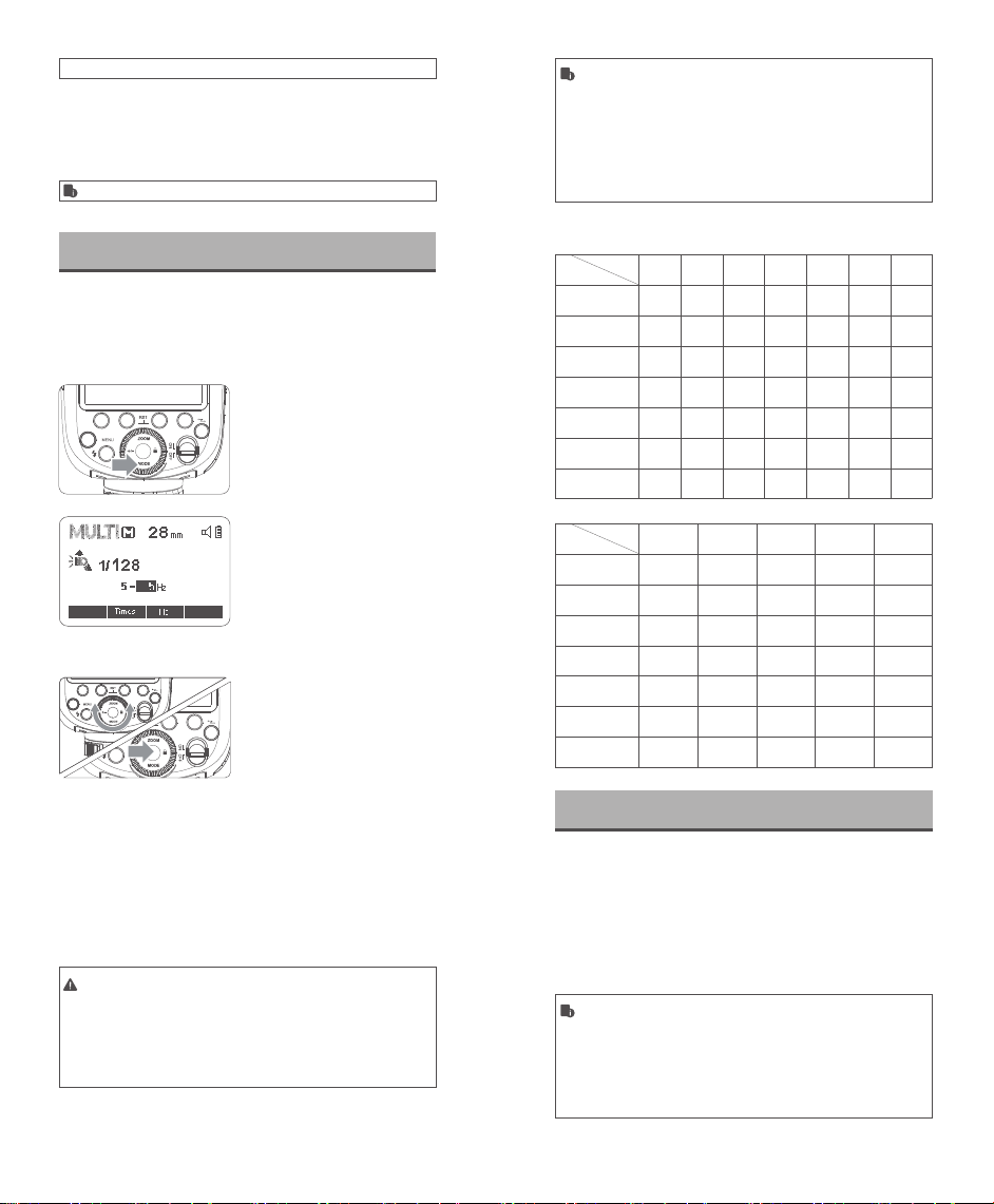
1
按<MODE>模式选择按
钮,屏幕显示<M>。
2
先按<+/->选中功率,转动
调节旋钮设置闪光输出功
率。
3
按下设置按钮,确定闪光
输出功率。
您可以在1/256功率至1/1全功率间以1/10档为增量设置闪
光输出。
为获得正确的闪光曝光,请使用手持的闪光测光表确定所需
的闪光输出。
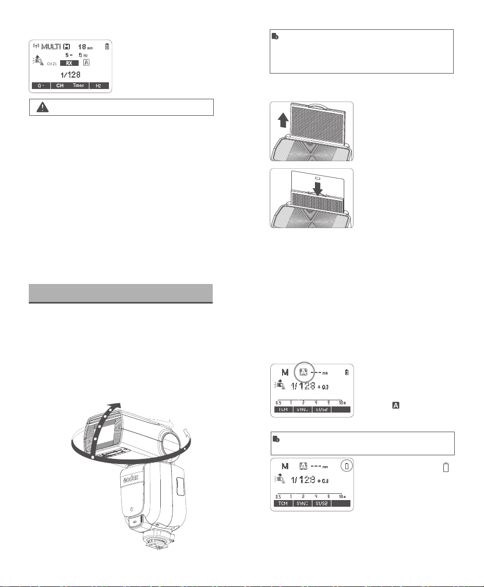
S1光控单元设置
在M手动闪光模式下,可以使用S1功能,闪光灯可作为副灯
使用,创造多种照明效果,适用于手动闪光环境。它会与主闪
光灯的第一次闪光同步触发闪光,效果与使用无线引闪器一
致。
- 07 - - 08 -
后帘同步功能在相机菜单里设置,请查看相机说明书。