Godrej Eyetrace Elite ET 8L1E User manual

USER MANUAL
ET 8L1E
All manuals and user guides at all-guides.com
all-guides.com

DVR User’s Installation and Operation Manual
Welcome
Thank you for purchasing our DVR.
This manual is designed to be a reference tool for the installation and operation of your
system.
Here you can find information about this series, DVR features and functions as well as a
detailed menu tree.
Before installation and operation, please read the following safeguards and warnings
carefully!
Important Safeguards and Warnings:
1. Do not place heavy objects on DVR.
2. Do not let any solid or liquid fall into or infiltrate the DVR.
3. Please brush printed circuit boards (PCBs), connectors, fans, machine box and so on
regularly.
4. Before the dust cleaning, please Switch OFF the power supply and unplug it.
5. Do not disassemble or repair the DVR by yourself. Do not replace the components by
yourself.
Environment:
1. Please place and use the DVR between 0 –40 degree Celsius. Avoid direct sunlight. Stay
away from heat source.
2. Do not install the DVR in damp environment.
3. Do not use the DVR in smoky and dusty environment.
4. Please ensure that the DVR level installation is in a stable workplace.
5. Please install in ventilated place. Keep the vent clean.
6. Use within the rating input and output scope.
All manuals and user guides at all-guides.com

Table of Contents
1. Product Introduction.............................................................................................................5
1.1 Product overview................................................................................................................5
1.2 Main functions ...................................................................................................................5
2. DVR Description ....................................................................................................................6
2.1 Description of front panel...................................................................................................6
2.2 Description of rear panel.....................................................................................................6
2.3 Hard Disk Installation..........................................................................................................7
3. Basic operation......................................................................................................................7
3.1 Turn on................................................................................................................................7
3.2 Turn off................................................................................................................................7
3.3 Login....................................................................................................................................7
3.4 Preview................................................................................................................................8
3.5 Desktop shortcut menu.......................................................................................................8
3.5.1 Main menu.......................................................................................................................8
3.5.2 Video playback.................................................................................................................9
3.5.3 Record Mode..................................................................................................................10
3.5.4 Alarm output..................................................................................................................10
3.5.5 PTZ control.....................................................................................................................11
3.5.6 Colour Settings...............................................................................................................14
3.5.7 TV Adjust........................................................................................................................14
3.5.8 Logout............................................................................................................................14
3.5.9 Window switch...............................................................................................................14
4. Main Menu..........................................................................................................................14
4.1 Main menu navigation......................................................................................................14
4.2 Recording function............................................................................................................16
4.2.1 Recording Configuration................................................................................................16
4.2.2 Video playback...............................................................................................................17
4.2.3 Video backup..................................................................................................................17
4.3 Alarm Function..................................................................................................................17
4.3.1 Motion Detect................................................................................................................18
4.3.2 Video Blind.....................................................................................................................19
4.3.3 Video Loss......................................................................................................................19
4.3.4 Alarm input.....................................................................................................................19
4.3.5 Alarm output..................................................................................................................19
4.3.6 Abnormality....................................................................................................................20
4.4 System setup.....................................................................................................................20
4.4.1 General setup.................................................................................................................20
4.4.2 Encode setup..................................................................................................................21
4.4.3 Network setup................................................................................................................21
4.4.4 Network service.............................................................................................................22
4.4.5 GUI display.....................................................................................................................24
4.4.6 PTZ setup........................................................................................................................24
4.4.7 Serial port setup.............................................................................................................25
4.4.8 Tour setup......................................................................................................................25
4.5 Management tools............................................................................................................25
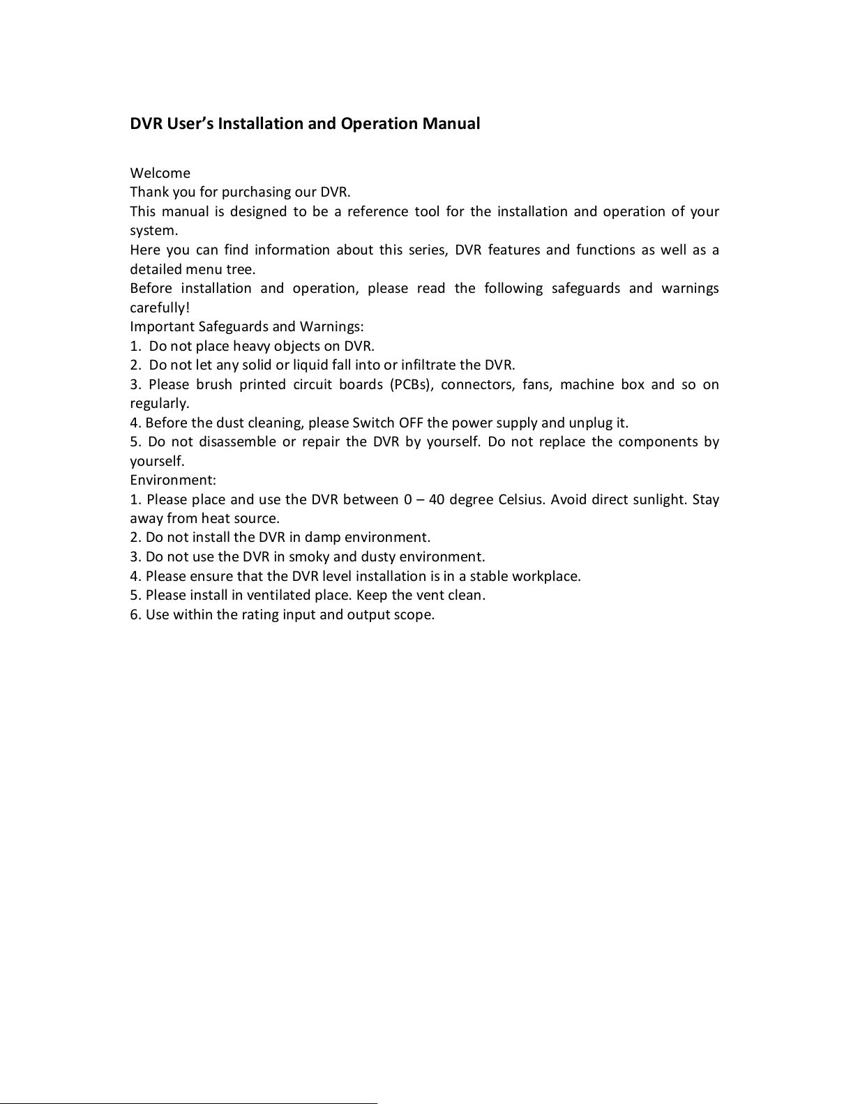
4.5.1 Hard disk management..................................................................................................25
All manuals and user guides at all-guides.com

4.5.2 User management..........................................................................................................26
4.5.3 Online user.....................................................................................................................27
4.5.4 TV Adjust........................................................................................................................27
4.5.5Auto maintenance...........................................................................................................28
4.5.6 Resume default..............................................................................................................28
4.5.7 Upgrade..........................................................................................................................28
4.6 System information...........................................................................................................29
4.6.1 Hard disk information....................................................................................................29
4.6.2 Code stream statistics....................................................................................................29
4.6.3 Log information..............................................................................................................29
4.6.4 Edition information........................................................................................................29
4.7 Shut down system.............................................................................................................29
5. FAQs and Maintenance.......................................................................................................30
5.1 FAQs..................................................................................................................................30
5.2 Maintenance.....................................................................................................................34
Appendix 1.Remote controller operation ..............................................................................34
Appendix 2.Mouse Operation.................................................................................................35
Information on E-waste handling and management..............................................................36
Warranty.................................................................................................................................37
All manuals and user guides at all-guides.com

1. Product Introduction
1.1 Product overview
The series DVR is designed especially for security and defense field which is outstanding
Digital Surveillance product. It introduces embedded LINUX operating system which is more
stable. It introduces standard H.264 video compression format and G 711A audio
compressed format which ensures the high quality image, low error coding ratio and single
frame playing. It introduces TCP/IP network technology which achieves the strong network
communication ability and telecommunication ability. The series DVR can be used
individually or online applied as a part of a safety surveillance network. With the
professional network video surveillance software it achieves the strong network
communication ability and telecommunication ability. The series DVR can be applied in the
bank, telecom, electric power system, judicial system, factory, storehouse, water
conservancy and so on.
1.2 Main functions
Real-time surveillance
·Analog interface and VGA interface (VGA interface is equipped selectively).
·Surveillance function through monitor or display.
Storage
·Special storage format which ensures the data safety.
Compression
·Real time compression which ensures the audio and video signal stable
synchronization.
Backup
·Through SATA interface and USB interface such as USB equipment, removable hard
disk and so on.
·Through net download the files in the hard disk.
Playback
·Individual real time video recording as well as searching, playback, network
surveillance, recording check, downloading and so on.
·Multi-Playback mode zooms at arbitrary region.
Net operating
·Through net tele-surveillance in the real time.
·Tele-PTZ control.
·Tele-recording and real time playback.
Alarm linkage
All manuals and user guides at all-guides.com

·Multi-route relay output which is convenient for the alarm linkage and light control
and the sort.
·Protecting circuits at the alarm input and output interface which protects the main
machine from damage.
Communication interface
·RS485 interface which fulfills the PTZ control.
·Standard Ethernet network interface which fulfills the telecommunication function.
Intelligent operating
·Mouse action function.
·Fast copy and paste operating for the same setting.
2. DVR Description
2.1 Description of front panel:
Screen
To
Power ON/OFF
the s
creen
LED Indications To show the working status of the DVR.
"REC”is recording indicator; "POW”is
power indicator;
IR receiver
Receive signal from remote control.
REC Press it to view record mode menu.
ESC
Press
it to exit from the inferior menu
and return to the superior menu.
MENU
Press this key to
view
the main menu.
Direction & confirm Keys
In menu mode, select the listed options
upward/ downward/ leftward/
rightward; In PTZ, control the dome to
upward/downward/ rotate/leftward/
rightward. Enter key confirms the
selection and operation.
USB2.0 To connect Backup Device
Mouse
To connect USB mouse
2.2 Description of rear panel:
Name Description
Video Input
Standard BNC port connected with the Camera.
Video output
Connected with the video input of the monitor.
VGA
VGA video signal output port connected with a VGA port of a
computer monitor.
Audio output
Connected with earphone or cable speaker.
Audio input port
Connected to audio input device.
All manuals and user guides at all-guides.com
all-guides.com

“485”(AB) port
RS485, it can connect PTZ or decoder, and can Control PTZ via the
panel, mouse, remote control and network.
USB port Connected to USB Pen-drive or mouse and used for system
software upgrade or video file backup
NET
RJ
-
45 network port connected to network cable and used for
remote browse or control.
Power
Power input is DC 12V/2
A.
2.3 Hard Disk Installation
·Take off the cover
·Fix the HDD to the housing with help of screws
·Fix the DVR cover
3. Basic operation
3.1 Turn on
Plug the power supply and turn on the power supply switch. Power supply indicator light
indicates “turning on”of the video recorder. After the startup you will hear a beep. The
default setting of video output is multiple-window output mode. If the startup time is within
the video setting time, the timing video recording function will start up automatically. Then
the corresponding channel is shining and the DVR is working normally. Note:
1. Make sure that the input voltage corresponds with the switch of the DVR power supply.
2. Power supply demands: 220V ±10% /50Hz.
3. Suggest using the UPS to protect the power supply under allowable conditions.
3.2 Turn off
There are two methods to turn off the DVR. Entering [main menu] and choosing [turn off] in
the [turn off the system] option is called soft switching. Pressing the power supply switch is
called hard switching. Illumination:
·Auto resume after power failure. If the DVR is shut down abnormally, it can
automatically backup video and resume previous working status after power failure.
·Replace the hard disk. Before replacing the hard disk, the power supply switch in the
rear panel must be turned off.
·Replace the battery. Before replacing the battery, the setting information must be
saved and the power supply switch in the real panel must be turned off. The DVR
uses button battery. The system time must be checked regularly. If the time is not
correct you must replace the battery, we recommend replacing the battery every
year and using the same battery type.
Note: The setting information must be saved before replacing the battery, otherwise,
information will be lost.
3.3 Login
When the DVR boots up, the user must login and the system provides the corresponding
functions with the user purview. There are two user settings. The names are 'admin' and
'guest'. These names have no password. 'Admin' is the super user purview; and 'Guest'
All manuals and user guides at all-guides.com

permissions are preview and video playback. User 'admin' and 'guest' passwords can be
revised, while their permissions can’t be revised. Password protection: If the password is
continuous wrong three times, the alarm will start. If the password is continuous wrong five
times, the account will be locked. (The account can be unlocked through reboot or after half
an hour, the account will be unlocked automatically). For your system security, please
modify your password after first login.
Picture 3.1 Login
3.4 Preview
You can right click mouse to choose to switch between the windows. The system date, time
and channel name are shown in each viewing window. The surveillance video and the alarm
status are shown in each window.
3.5 Desktop shortcut menu
In preview mode you can right click mouse to get a desktop shortcut menu. The menu
includes: main menu, video playback, video control, alarm output, PTZ control, color setup,
TV adjust, shut down system, window switch.
3.5.1 Main menu
When you login, the system main menu is shown as below.
Picture 3.2 Main menu Picture 3.3 video playback
All manuals and user guides at all-guides.com

Picture 3.4 detect the storage Picture 3.5 Recording backup
3.5.2 Video playback
There are two methods for you to play the video files in the hard disk.
1. In the desktop shortcut menu.
2. Main menu > video recording > video playback.
Note: The hard disk that saves the video files must be set as read-write or read-only state.
[Listed files] Look up the listed files that accord with the searching criteria.
[File information] Look up the found file information.
[File backup] Backup the chosen file. Click the button and operate as followed.
Note: The storage must be installed before the file backup. If the backup is terminated,
the already existing backup can playback individually.
Detect: Detect the storage connected with the DVR such as hard disk or universal disk.
Erase: Choose the file to delete and click 'Erase' to delete the file.
Stop: Stop the backup.
Backup: Click 'Backup' button and the dialog box is popped up. You can choose the backup
file according to type, channel and time.
Remove: Clear the file information.
Add: Show the file information satisfying the set file attributes.
Start/Pause: Click the 'Play' button to start the backup and click the 'Pause' button to stop
the backup.
Cancel: During backup you can exit the page layout to carry out their functions.
[File searching]: Search the file according to the searching parameter.
Picture 3.6 File searching
All manuals and user guides at all-guides.com

File type: Set the searching file type.
Channel: Set the searching channel.
Start Time: Set the searching time scan.
Playback control: Refer to the following sheet for more information.
Button
Function
Button
Function
Play/pause
Backward
Stop
Volume
Slow play
Fast play
Previous frame
Next frame
Previous file
Next file
Repeat playback
Full screen
Operation hint: Displays the function of the cursor place.
NOTE: Frame by frame playback is only performed in the pause playback mode Special
Functions: Accurate playback: Input time (H/M/S) in the time column and then click 'Play'.
The system can operate accurate playback according to the searching time.
Local zoom: When the system is in single-window full-screen playback mode, you can drag
your mouse in the screen to select a section and then left click mouse to realize local zoom.
You can right click mouse to exit.
3.5.3 Record Mode
Please check current channel status: “o”means it is not in recording status “●” means it is in
recording status. You can use desktop shortcut menu or click [main menu] > [recording set]
to enter the recording control interface.
[Schedule] Record according to the configuration.
[Manual] Click the 'All' button and the corresponding channel starts recording, no matter
the channel in any state.
[Stop] Click the 'Stop' button and the corresponding channel stops recording, no matter the
channel in any state.
3.5.4 Alarm output
Picture 3.8 Alarm output Picture 3.9 PTZ Setup
All manuals and user guides at all-guides.com

Picture 3.10 Preset Settings Picture 3.11 PTZ Control
3.5.5 PTZ control
Operation interface is as follows. The functions include: PTZ direction control step, zoom,
focus, iris, setup operation, tour between spots, trial tour, boundary scan, assistant switch,
light switch, level rotation and so on. Note
1. Decoder A(B) line connects with DVR A(B) line. The connection is right.
2. Click [main menu] > [system configuration] > [PTZ setup] to set the PTZ parameters.
3. The PTZ functions are decided by the PTZ protocols.
[Step] Set the PTZ rotation range, Default range 1-8.
[Zoom]click +/ - button to adjust the zoom multiple of the camera.
[Focus]click +/ - Button to adjust the focus of the camera.
[Iris] click +/ - Button to adjust the iris of the camera.
[Direction control] Control the PTZ rotation, 8 directions control is supportive, (4 directions
in front panel is supportive).
[High speed PTZ] Full screen shows channel image, left press mouse and control PTZ to
rotate, then rotate the mouse to adjust the zoom multiple of the camera.
[Setup] Enter the function operation menu.
[Window switch] Switch between different windows.
Special Function:
1. Preset. Set a location for the preset, calls the preset points, PTZ automatically turns to the
set position.
1) Preset option
Set a location for the preset, procedure is as follows:
Step 1:In picture 3.10, clicking the direction buttons will turn into preset position, click the
'set' button to enter Picture 3.11.
Step 2:Click the 'Preset' button, then write the preset points in the input box.
Step 3:Click 'Set' button, return to the picture 3.10. Complete setup that is the preset points
and preset position corresponds to the values entered.
DEL Preset: After entering preset points, click 'Del Preset' button to remove the preset.
2) Preset point calls
In picture 3.10, click 'Page switch' button, enter PTZ control interface as shown in picture
3.12. In the input blank, write the preset point number, then click 'Preset' button, PTZ turns
to the corresponding preset point.
All manuals and user guides at all-guides.com
all-guides.com

2. Tour between Points Multiple preset points connected tour line, call tour points, the PTZ
run around on the line.
1) Tour between points settings
Tour line is connected by multiple preset points, setting procedure is as follows:
Step 1: In picture 3.10, the Direction key will turn PTZ to designated location, click 'Set'
button to enter Picture 3.13.
Step 2: Click 'Tour' button, then write proper values in the 'Preset' box, then click 'Add
preset' button and complete settings (also can add or delete tour which has been set up).
Step 3: Repeat step 1 and step 2, until all the points in the preset designated tour is set.
Del Preset: Please input preset value in the box, click 'Del Preset' button to remove the
preset points.
Del Tour: Input the number of tour line, click 'Del Tour' button to remove the tour lines set.
2) The Calls of Tour between Points.
In picture 3.10, click 'Page Switch' button, enter PTZ control menu as shown in picture 3.12.
Please input the number of tour in the box, then click 'Tour' & PTZ begins to work on the
tour line.
Picture 3.12 Tour between point settings Picture 3.13 Scan Setup Picture
Picture 3.14 Boundary Scan Setup Picture 3.15 Auxiliary Function
3. Pattern PTZ also can work on the preset scan line repeatedly.
1) Pattern setup
Step 1: In picture 3.10, click 'Set' button, enter picture 3.14.
Step 2: Click Pattern button, then enter proper values in the scan box.
Step 3: Click Begin button, enter picture 3.10, here you can set the following terms: Zoom,
Focus, Iris, Direction and soon click 'Set' button to go back picture 3.14.
Step 4: Click 'End' button to complete setup. Click right button of the mouse to exit.
2) Pattern Calls
All manuals and user guides at all-guides.com

In picture 3.10, click 'Page Switch' button, then enter PTZ control menu as shown in picture
3.12. Please enter the number of the scan in the value box, then click 'AutoScan' button, PTZ
begins to work on the scan line.
4. Border Scan
1) Boundary Scan Setup
Step 1: In picture 3.10, click Direction button to turn the PTZ to preset direction, then click
'Set' button to enter Picture 3.15, select 'Border' button, then 'left' and return to picture
3.10.
Step 2: Please click direction arrows to adjust PTZ direction, click 'Set' button to enter
Picture 3.15. Select 'Border', then 'right' and return to picture 3.10.
Step 3: You have thus completed the setup of position of left and right boundary.
5. Horizontal Rotating
Click Horizontally rotating button, PTZ begins to rotate horizontally (relative to original
position of the camera). Click 'Stop' button to stop.
Picture 3.16 PTZ menu settings Picture 3.17 Image colour
Picture 3.18 TV adjust Picture 3.19 shut down the system
6. Rotate
Click on the Horizontal rotating button; PTZ turns around.
7. Reset
PTZ restart; all the data clears to 0.
8. Page Switch
All manuals and user guides at all-guides.com

In picture 3.12, click 'Page Switch' button to enter into picture 3.16, setting auxiliary
function. Enter Auxiliary number corresponding to auxiliary switch on the decoder.
[Auxiliary Number] The operation of corresponding auxiliary switch according to PTZ
agreement.
[Page Switch] In picture 3.16, click 'Page Switch' button to enter the Picture 3.17 PTZ Main
Menu, the menu itself can be controlled by the Menu control buttons.
Enter Menu: Enter PTZ menu.
Exit Menu: Exit PTZ menu.
Direction Button: The function buttons to choose PTZ menu.
Confirm/Cancel: To choose PTZ menu.
3.5.6 Colour Settings
Set the selective image parameters (current channel for single window display and cursor
place for multi-window display). You can use the desktop shortcut menu and enter the
interface. The image parameters include: tonality, brightness, contrast, saturation. You can
set different parameters at different time sections.
3.5.7 TV adjust
Adjust TV output area parameters. You can use the desktop shortcut menu or enter [main
menu]> [management tools]> [TV adjust]
3.5.8 Logout
Logout, shut down the system or reboot up. You can use the desktop shortcut menu or
enter [main menu].
[logout] Quit the menu. Offer password next time you want to login.
[shut down] Quit the password. Turn off the power supply. When press the shutdown
button, there is schedule hint. After three seconds, the system is shut down. Cancel midway
is of no effect.
[reboot] Quit the system. Reboot up the system.
3.5.9 Window switch
Preview in single window/four windows/eight windows/nine windows according to the
choice.
4. Main Menu
4.1 Main menu navigation
Main Menu Sub Menu Function
Recor
d
Record Conf.
Set the recording configuration, recording type, recording
time section.
Playback
Set recording look
-
up, recording play, video file storage
Backup Set motion detect alarm channel, sensitivity, area, linkage
parameters: defending time section, alarm output, screen
hint, recording, PTZ, tour.
All manuals and user guides at all-guides.com

Alarm
Motion
detection
Set motion detect alarm channel, sensitivity, area, linkage
parameters: defending time section, alarm output, screen
hint, recording, PTZ, tour.
Video Blind
Set camera mask alarm channel, sensitivity, linkage
parameters: defending, time section, alarm output,
screen hint, recording, PTZ, tour.
Abnormality
Set alarm (message or buzzer) for abnormal events such
as IP address conflict or full HDD.
Video lo
ss
Set video loss alarm channel, linkage parameters:
depending time section, alarm output, screen hint,
recording, PTZ, tour.
System
configuration
General
Set system time, data format, language, hard disk full
time operation, machine number, video format, output
made, summer time, stay time.
Encode
Set main (assistant) coding parameter: code mode,
resolving ability, frame rate, code stream control, image
quality type, code stream value, frame between value
video/audio enable.
Network
Set basic network parameters, DHCP and DNS
parameters, network high speed download.
Netservice
PPPOE, NTP, E
-
Mail purview, DDNS parameter.
GUI Display
Set channel name, purview hint icon state, transparency,
cover area, time title, channel time fold.
PTZ config
Set channel, PTZ protocol, address, baud rate, date bit,
stop bit.
RS232
Set serial port function, baud rate, date bit, stop bit,
check
Tour
Set tour mode and interval time
Digital
Set Channel mode
Advanced
Storage
Manage
Set appointed hard disk as read
-
write disc, read
-
only disc
or redundant disc, clear data, resume date and so on.
Account
Modify user, group or password. Add user or group.
Delete user or group.
Online user
Break the connection with the already logged in user.
Lock the account after break until booting up again.
Output Adjust
Adjust TV upside, downside, nearside, star
board distance.
Automatic
maintenance
Set automatic reboot system and automatic deleting files.
Restore
Resume setup state : common setup, code setup,
recording setup, alarm setup, network setup, network
service, preview playback, serial port setup, user
management
Upgrade
Upgrade Firmware
All manuals and user guides at all-guides.com

Device Info.
Configure device hardware information
Import/Expo
rt
Export current log setting, import the new settings
Info HDD Info Display hard disk capability and recording time
BPS
Display code stream information
Log
Clear all log information according to the log video and
time
Version
Display edition information
Logout
Logout, shut down or reboot
4.2 Recording function
4.2.1 Recording Configuration.
Set the recording parameters in the surveillance channel. The system is set for 24 hours
consecutive recording in the first startup. You can enter [Main menu] > [Recording function]
> [Recording setup] to set.
Note: There is at least one read-write hard disk.(refer to chapter 4.5.1)
Picture 4.1 recording setup
[Channel] Choose the corresponding channel number to set the channel. Choose the 'All'
option to set the entire channels.
[Redundancy] Choose the redundancy function option to implement the file double backup
function. Double backup is writing the video files in two hard disks. When you do the double
backup, make sure there are two hard disks installed. One is read-write disk and the other is
redundant disk. (refer to 4.5.1)
[Length] Set the time length of each video file. (60 minutes default value)
[Pre-Record] Record maximum 30 seconds before the action. (time length is decided by the
code stream)
[Mode] Set video state: schedule, manual or stop.
·Schedule: Record according to the set video type (regular, detection and alarm) and
time section.
·Manual: Click the button and the corresponding channel starts recording, no matter
the channel in any state.
·Stop: Click the stop button and the corresponding channel stops recording, no
matter the channel in any state.
All manuals and user guides at all-guides.com
all-guides.com

[Time section] Set the time section of common recording. The recording will start only in
the set range.
[Recording type] Set recording type: regular, detection or alarm.
·Regular: Perform the regular recording in the set time section. The video file type is
“R”.
·Detection: Trigger the “motion detect”, “camera mask”or “video loss”signal. When
above alarm is set as opening recording, the “detection recording”state is on. The
video file type is “M”.
·Alarm: Trigger the external alarm signal in the set time section. When above alarm is
set as opening recording the “detection recording”state is on. The video file type is
“A”.
Note: Refer to chapter 4.3 to set corresponding alarm function.
4.2.2 Video playback
Refer to chapter 3.5.2.
4.2.3 Video backup
You can back up the video files to external storage through setup.
Note: The storage must be installed before the files backup. If the backup is terminated,
the already existing backup can playback individually.
Picture 4.2 detect the equipment Picture 4.3 file backup
[Detect] Detect the storage connected with the DVR such as hard disk or universal disk.
[Erase] Choose the file to delete and click erasure to delete the file.
[Stop] Stop the backup.
[Backup] Click backup button and the dialog, box is popped up. You can choose the backup
file according to the type, channel and time.
Remove: Clear the file information.
Add: Show the file information satisfying the set file attributes.
Start/Pause: Click the play button to start the backup and click the pause button to stop the
backup.
Cancel: During backup you can exit the page layout to carry out other functions.
4.3 Alarm Function
Alarm functions include: motion detect, camera mask, video loss, alarm input and alarm
output.
All manuals and user guides at all-guides.com

4.3.1 Motion Detect
When system detects the motion signal that reaches the set sensitivity, the motion detect
alarm is on and the linkage function is turned on.
Picture 4.4 motion detect Picture 4.5 set the area
[Channel number] Choose the set motion detect channel.
[Enable] Means that the motions detect function is on.
[Sensitivity] Choose in the six options according to the sensitivity.
[Area] Click setup and enter the set area. The area is divided into PAL22X18. Green block
means the current cursor area. Yellow block means the dynamic detect defensive area.
Black block means the unfenced area. You can set the area as followed. Drag the mouse and
draw the area.
[Period] Trigger the motion detect signal in the set time section. You can set according to
week or set uniformly. Each day is divided into four time sections. Means the set valid.
[Interval] Only one alarm signal is turned on (even there are several motion detect signals)
in the set interval.
[Delay] Delay a few moments and stop when the alarm state is turned off. The range is 10-
300 seconds.
[Record channel] Choose the recording channel (multiple options supportive). Trigger the
video signal when the alarm is turned on.
Note: Set in the [recording channel] and perform the linkage recording. Start detecting
video files in the corresponding time section.
[PTZ Activation] Set the PTZ linkage when the alarm is turned on.
Picture 4.6 set the time section Picture 4.7 PTZ Activation
All manuals and user guides at all-guides.com

Note: PTZ linkage is set in the [shortcut menu] > [PTZ control]. Set the tour between spots,
trail tour and so on.
[Show message] Pop the alarm information dialog box in the local host computer screen.
[E-Mail] Means sending an E-mail to user when the alarm is turned on.
Note: Set in the [network service] and send an E-Mail.
4.3.2 Video Blind
When the video image is influenced by the environment such as bad brightness or reaching
the set sensitivity parameter, the camera mask function is turned on and the linkage is
turned on. Set method: refer to chapter 4.3.1.
Picture 4.8 camera mask Picture 4.9 video loss
Picture 4.10 alarm input Picture 4.11 Abnormality
4.3.3 Video Loss
When the equipment cannot obtain the channel video signal , the video loss alarm is turned
on and the linkage function is turned on.
Set method: refer to chapter 4.3.1.
4.3.4 Alarm input
When the equipment obtains the external alarm signal, the alarm function is turned on.
Set method: refer to chapter 4.3.1.
4.3.5 Alarm output
Refer to chapter 3.5.4.
All manuals and user guides at all-guides.com

4.3.6 Abnormality
Analyzing and inspecting current software and hardware of the device: When some
abnormal events happen the device will make a relative answer such as show message and
buzzer.
[Event type] Selecting abnormity you want to inspect.
[Enable] Select it to make sure abnormal function workable.
[Show message] Automatically alarm cue dialog box come out of the main screen.
[Buzzer] The buzzer rings when alarm occurs.
4.4 System setup
Set the system parameters such as general setup, code setup, network setup, network
service, output mode, PTZ control, serial port setup and alternate patrol setup.
4.4.1 General setup
[System time] Set system data and time.
[Data format] Choose the data format: YMD, MDY, DMY.
[Date separator] Choose list separator of the data format.
Picture 4.12 regular setup Picture 4.13 week setup
Picture 4.14 date setup
[Time format] Choose time format: 24-hour or 12-hour.
[Language] English or Chinese.
[Hard disk full]
·Choose stop: Stop recording when the hard disk is full.
·Choose cover: Cover the earliest recording files and continue recording when the
hard disk is full.
[DVR Number] Only when the address button in the remote controller and the
corresponding DVR number is matched, the remote operation valid.
[Video format] PAL or NTSC.
All manuals and user guides at all-guides.com
Table of contents
Other Godrej DVR manuals