manuals.online logo
Brands
  1. Home
  2. •
  3. Brands
  4. •
  5. Gold Note
  6. •
  7. Turntable
  8. •
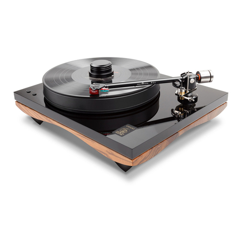
  9. Gold Note Bellagio Reference User manual

Gold Note Bellagio Reference User manual

OWNER’S MANUAL
Bellagio Reference
OWNER’S MANUAL page 1
IMPORTANT SAFETY INFORMATION
CAUTION: TO REDUCE THE RISK OF ELECTRIC SHOCK, DO NOT REMOVE COVER (OR
BACK). NO USER-SERVICEABLE PARTS INSIDE. REFER SERVICING TO QUALIFIED
SERVICE PERSONNEL.
The lightning flash with arrowhead symbol, within equilateral triangle, is intended to alert the
user to the presence of uninsulated “dangerous voltage” within the product’s enclosure that
may be of sufficient magnitude to constitute a risk of electric shock to persons.
The exclamation point within an equilateral triangle is intended to alert the user to the presence
of important operating and maintenance (servicing) instructions in the literature accompanying
the appliance.
This appliance has a serial number located on the rear panel.
Please record the model and serial numbee and retain them for
your records.
Serial Number: Model:
WARNING
TO PREVENT FIRE OR SHOCK HAZARD,
DO NOT EXPOSE THIS APPLIANCE TO RAIN
OR MOISTURE
Do not disassemble any part of the product.
Do not use any part of the product for other purposes.
For service and problems of any kind, contact qualified Gold Note personnel.
Protect the product from rain and humidity and keep away from heat sources, electric and
electronic motors etc.
The power Chord supplied must be used only on this unit.
Gold Note does not have responsibility for any improper use of this unit
OWNER’S MANUAL page 2
IMPORTANT SAFETY INFORMATION
1Read these instructions.
2Keep these instructions.
3 Heed all warnings.
4 Follow all instructions.
5 Do not use this apparatus near to any water.
6 Clean only with dry cloth.
7Do not block any ventilation openings. Install in accordance
with the manufacturer's instructions.
8Do not install near any heat sources such as radiators, heat
registers, stoves, or other apparatus (including amplifiers) that
produce heat.
9 Do not defeat the safety purpose of the polarized or ground-
ing-type plug. A polarized plug has two blades with one wider
than the other. A grounding type plug has two blades and a third
grounding prong. The wide blade or the third prong are provid-
ed for your safety. If the provided plug does not fit into your
outlet, consult an electrician for replacement of the obsolete
outlet.
10 Protect the power cord from being walked on or pinched
particularly at plugs, convenience receptacles, and the point
where they exit from the apparatus.
11 Only use attachments/accessories specified by the manufac-
turer.
12 Use only with the cart, stand, tripod, bracket, or table
specified by the manufacturer, or sold with the apparatus. When
a cart is used, use caution when moving the cart/apparatus
combination to avoid injury from tip-over.
13 Unplug this apparatus during lightning storms or when
unused for long periods of time.
14 Refer all servicing to qualified service personnel. Servicing is
required when the apparatus has been damaged in any way,
such as power-supply cord or plug is damaged, liquid has been
spilled or objects have fallen into the apparatus, the apparatus
has been exposed to rain or moisture, does not operate
normally, or has been dropped.
• Do not expose this apparatus to drips or splashes.
• Do not place any objects filled with liquids, such as vases, on
the apparatus.
• Do not install this apparatus in a confined space such as a
book case or similar unit.
• The apparatus draws nominal non-operating power from the
AC outlet with its POWER or STANDBY/ON switch not in the ON
position.
• The apparatus should be located close enough to the AC
outlet so that you can easily grasp the power cord plug at any
time.
• The main plug is used as the disconnect device, the discon-
nect device shall remain readily operable.
• If the product uses batteries (including a battery pack or
installed batteries), they should not be exposed to sunshine, fire
or excessive heat.
• Caution should be taken when using earphones or head-
phones with the product because excessive sound pressure
(volume) from earphones or head- phones can cause hearing
loss.
OWNER’S MANUAL page 3
INTRODUCTION
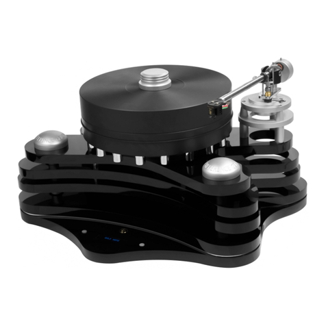
Five Different Curved Plinths
The Bellagio Reference features five each other different
curved plinths enabling maximum stiffness and indeforma-
bility and allowing the best resonance feedback control.
Plinths are interfaced with different thickness titanium
spacers joined each other with specially curved machined
solid block aluminium and extra-large feet.
The Platter Bearing/Spindle
The Bellagio Reference features one of the best platter
bearing/spindle ever made for a turntable. The spindle is
made of the hardest carbon steel hardened with a boiling
oil process than rectified and polished to guarantee a
perfect working fluidity. The bearing is made of polished
bronze with a total tolerance of 1/100 millimeter.
The Turntable Power Control
The Bellagio Reference is the only turntable that features
a power control generator based on PWM technology –
Pulse Width Modulation. The PWM power drive generates
the power AC-DC-AC enabling the best coupling of the two
AC semi-wave for a perfect coupling literally annulling any
motor resistance or vibration and allowing the highest
motor torque at the same time.
High-End Turntable With Remote Control –
OPTIONAL
The Bellagio Reference features optionally a remote
control allows the control of all the main functions:
ON/OFF, speed change, speed control and power control
of the unit.
A Power Control System for Your Music – OPTION-
AL
The Bellagio Reference features optionally an unique
“power control system” allowing to control the torque of
the motor to finely adjust the turntable “musical charac-
ter”. Powering the motor with a lower torque is indicated
to play, for instance, ancient or chamber string music
where details strongly matter, while the maximum torque is
indicated for rock or symphonic music enabling more
dynamic. The power control system is conveniently
performed by the remote control to let the listener adjust
the way to play the turntable directly from his listening
point.
All Gold Note products are proudly designed, manufactured and assembled in Italy 100%
OWNER’S MANUAL page 4
CONTENT OF PACKAGING: Layer A1
1) 110mm thick Platter made of Sustarin Acetamide and 16 peripheral counterweights (1x)
2) Platter Clamp (1x)
3) Turntable foot (3x)
4) Platter Spindle Tip that clamps the platter (1x)
5) Motor Cylinder completed with motor Pulley (1x)
6) Motor Pulley Cover (1x)
7) Tone Arm Bottom Flange (1x)
8) Tone Arm Flange Conical Spacers (6x)
9) Tone Arm Board (2x)
10) Gold Note Arm Flange Adapter (Rega compatible) (1x)
11) Covers for Threaded Bar (3x)
A1
10 3 3
3
2
6
1
11
11
5
4
8
7
9
OWNER’S MANUAL page 5
CONTENT OF PACKAGING: Layer A2
A2
1
2
5 3
6
4
1) Top three layer black acrylic plinth (1x)
2) Threaded Stainless Steel bar (3x)
3) Delrin Top Plinth Conical Support (3x)
4) Tone Arm Flange Bottom Support (3x)
5) Front Aluminium Conical Support Cover (2x)
6) Rear Conical Support Cover (1x)
OWNER’S MANUAL page 6
CONTENT OF PACKAGING: Layer A3
A3
1
1) CPU black acrylic double plinth with display and keyboard to control the turntable (1x)
OWNER’S MANUAL page 7
CONTENT OF PACKAGING: Layer A4
1
2
3
1) Rectangular Box area
- O-ring for CPU plinth spacer (3x)
- Motor cable with mini XLR connector (1x)
- Belt (1x)
- Grease vessel for tunrtable legs threading (1x)
- Oil vessel for Platter Spindle/Bearing (1x)
-13mm Wrench for blocking brass threaded bar nuts (1x)
- 10mm L shape Titanium Wrench for top plinth height adjusting (1x)
- 2mm Allen wrench with handle (1x)
- 3mm Allen wrench for Flanges fixing screws (1x)
- 5mm Allen wrench for Motor fixing screws (1x)
- 6x60mm Motor Allen Screws (2x)
- Arm Board Flange Screws (3x)
- Brass Threaded Bar Nut & Nnylon Washer (3x)
- 4x40mm Arm Board Allen Screws (3x)
2) Power Supply Unit
- Stroboscope (1x)
- Gold Note Gel Mat (1x)
- Special anti scratch super grip gloves (1pr.)
3) Power chord (1x)
OWNER’S MANUAL page 8
STEP 1
Threaded Titanium bar (3x) located in layer A2 position 2
Brass Threaded Bar Nut & Nnylon Washer (3x ea.) available inside the bag
marked SL01 located in layer A4 position 1
For the STEP 13 you need these parts:
ASSEMBLING TURNTABLE TOP PLINTH [Threaded Bars]
STEP 13-1 COMPLETED
10mm
55mm
60mm
O-Ring
(premounted)
Threaded
Titanium bar Brass Nut Nylon Washer
+
STEP 1-1
Thread the Brass threaded bar Nuts and white Nylon Washers as shown in the picture below
OWNER’S MANUAL page 9
STEP 2
ASSEMBLING TURNTABLE TOP PLINTH [Threaded Bars]
STEP 2-1
Thread the Stainless Steel Threaded Bars with the
Nuts/Washers facing down into the CPU plinth till legs
as swhon in the picture aside
STEP 2-3
Thighten the Stainless Steel Threaded Bar’s
nut
with the 13mm Wrench supplied, to block the
structure firmly. Be sure to position the Nylon
STEP 2-2
Thread the Stainless Steel Threaded Bars
from the bottom side 15mm out
Feet to lock on the S/Steel Threaded Bar (3x) located in A1 position 12
For the STEP 3 you need these parts:
OWNER’S MANUAL page 10
STEP 3
ASSEMBLING TURNTABLE TOP PLINTH [Threaded Bars]
STEP 3
Firmly thread the feet on the S/Steel Threaded Bars
as shown in the picture below.
OWNER’S MANUAL page 11
STEP 4
ASSEMBLING TURNTABLE TOP PLINTH [Threaded Bar Covers]
STEP 4
Insert the Covers on the S/Steel Threaded Bar
as shown in the pictures aside and below
Bottom
Top
(this side UP)
Covers for Threaded Bar (3x) located in A1 position 11
For the STEP 4 you need these parts:
OWNER’S MANUAL page 12
STEP 5
ASSEMBLING TURNTABLE TOP PLINTH [Top Plinth Conical Supports]
STEP 5
Thread the Delrin Top Plinth Conical Supports in the titanium Threaded Bars till circa 5mm close to the
Threaded Bar Covers.
Delrin Top Plinth Conical Supports (3x) located in A2 position 3
For the STEP 5 you need these parts:
OWNER’S MANUAL page 13
STEP 6
ASSEMBLING TURNTABLE TOP PLINTH [Triple Plinth]
Top three layer black acrylic plinth (1x) located in A2 position 1
For the STEP 6 you need these parts:
If you need to install a 12” Tone Arm Please go first to the
OPTION MOUNTING INSTRUCTION pag.48
OWNER’S MANUAL
STEP 7
ASSEMBLING TURNTABLE TOP PLINTH [Motor]
STEP 7-1
Insert the Motor cable with mini XLR connectors
into the Cable Pipe as shown in the picture aside
Motor Cylinder completed with motor Pulley (1x) located in A1 position 3
For the STEP 19 you need these parts:
Motor Allen Screws with Nylon Washers (2x ea.) available
inside the bag marked SL02 located in A4 position 1
Motor cable with mini XLR connectors (1x) available inside the bag
marked SL02 located in A4 position 1
+
page 14
OWNER’S MANUAL
STEP 7
ASSEMBLING TURNTABLE TOP PLINTH [Motor]
STEP 7-2
Plug the other side of the Motor cable Mini XLR
connector into the bottom of Motor as shown
in the picture aside
STEP 7-3
Lay the Motor Xinto the hole as shown in the
picture aside.
page 15
OWNER’S MANUAL
STEP 7
ASSEMBLING TURNTABLE TOP PLINTH [Motor]
STEP 7-4
With the help of the 5mm Allen wrench located
in the layer B6 position 6, thread the Motor
Allen Screws with Nylon Washers into
the slots as shown in the picture
aside.
STEP 7-5
The Motor Allen Screws must be thigtened for
blocking the Motor Cylinder firmly.
page 16
OWNER’S MANUAL
STEP 8
ASSEMBLING TURNTABLE TOP PLINTH [Platter]
110mm thick Platter made of Sustarin Acetamide and 16 peripheral
counterweights (1x) located in A1 position 1
For the STEP 8 you need these parts:
Platter Spindle Tip that clamps the platter (1x) located in A1 position 4
STEP 8-1
Lay down the Platter of the turntable as shown in the picture taking care it perfectly fits the
spindle flat surface.
page 17
OWNER’S MANUAL
ASSEMBLING TURNTABLE TOP PLINTH [Platter]
STEP 8-2
Thread the Platter Spindle Tip as show in the picture
STEP 8-3
The conical shape of the Platter Spindle Tip once frimly threaded
perfectly clamps the Turntable platter
page 18
OWNER’S MANUAL
STEP 9
ASSEMBLING TURNTABLE TOP PLINTH [Arm Board]
Tone Arm Flange Bottom Support (6x) located in A2 position 4
Tone Arm Flange Conical Spacers (6x) located in A1 position 8
Tone Arm Board (2x) located in A1 position 9
Gold Note Arm Flange Adapter (Rega compatible) (2x) located
in A1 position 10
4x40 Arm Board Allen Screws (6x) inside the bag marked as SL03
located in A4 position 1
For the STEP 23 you need these parts:
Tone arm Bottom Flange (2x) located in A1 position 7
The step 23 shows you how to assemble the two standard 9” Tone Arm Board
If you wish to install the 12” Tone Arm Please go first to the
OPTION MOUNTING INSTRUCTION pag.48
page 19

Other manuals for Bellagio Reference

1

Other Gold Note Turntable manuals

Gold Note MEDITERRANEO User manual

Gold Note

Gold Note MEDITERRANEO User manual

Gold Note Bellavista Signature User manual

Gold Note

Gold Note Bellavista Signature User manual

Gold Note VALORE Plus 425 User manual

Gold Note

Gold Note VALORE Plus 425 User manual

Gold Note VALORE 425 Lite User manual

Gold Note

Gold Note VALORE 425 Lite User manual

Gold Note GIGLIO User manual

Gold Note

Gold Note GIGLIO User manual

Gold Note MACHIAVELLI RED MKII User manual

Gold Note

Gold Note MACHIAVELLI RED MKII User manual

Gold Note PIANOSA User manual

Gold Note

Gold Note PIANOSA User manual

Gold Note VASARI RED User manual

Gold Note

Gold Note VASARI RED User manual

Gold Note Vasari Red User manual

Gold Note

Gold Note Vasari Red User manual

Gold Note Vasari Gold User manual

Gold Note

Gold Note Vasari Gold User manual

Gold Note VALORE Compact User manual

Gold Note

Gold Note VALORE Compact User manual

Gold Note Bellavista Maggiore User manual

Gold Note

Gold Note Bellavista Maggiore User manual

Gold Note DA VINCI User manual

Gold Note

Gold Note DA VINCI User manual

Gold Note Valore 400 User manual

Gold Note

Gold Note Valore 400 User manual

Gold Note VALORE 425 Lite User manual

Gold Note

Gold Note VALORE 425 Lite User manual

Gold Note B-5.1 User manual

Gold Note

Gold Note B-5.1 User manual

Gold Note GIGLIO User manual

Gold Note

Gold Note GIGLIO User manual

Gold Note GIOTTO User manual

Gold Note

Gold Note GIOTTO User manual

Gold Note Machiavelli Red User manual

Gold Note

Gold Note Machiavelli Red User manual

Gold Note PIANOSA User manual

Gold Note

Gold Note PIANOSA User manual

Gold Note MEDITERRANEO User manual

Gold Note

Gold Note MEDITERRANEO User manual

Gold Note Bellagio Reference User manual

Gold Note

Gold Note Bellagio Reference User manual

Gold Note MACHIAVELLI MkII GOLD User manual

Gold Note

Gold Note MACHIAVELLI MkII GOLD User manual

Gold Note GIGLIO User manual

Gold Note

Gold Note GIGLIO User manual

Popular Turntable manuals by other brands

Colorlight C6 user manual

Colorlight

Colorlight C6 user manual

LENCO Classic Phono TCD-2551 user manual

LENCO

LENCO Classic Phono TCD-2551 user manual

nedis TURN300BK user manual

nedis

nedis TURN300BK user manual

Aiwa PX-E860 Service manual

Aiwa

Aiwa PX-E860 Service manual

Solon EL00041 manual

Solon

Solon EL00041 manual

Crosley CR8005U instruction manual

Crosley

Crosley CR8005U instruction manual

LENCO L-78 USB - quick guide

LENCO

LENCO L-78 USB - quick guide

Picup Media GemLightbox Eclipse user manual

Picup Media

Picup Media GemLightbox Eclipse user manual

iLive ITTB401DW user guide

iLive

iLive ITTB401DW user guide

Harman Kardon SC1510 owner's manual

Harman Kardon

Harman Kardon SC1510 owner's manual

VPI Industries Signature 21 manual

VPI Industries

VPI Industries Signature 21 manual

Dual 721 operating instructions

Dual

Dual 721 operating instructions

VPI Industries ARIES 3 Setup manual

VPI Industries

VPI Industries ARIES 3 Setup manual

Victrola Revolution GO quick start guide

Victrola

Victrola Revolution GO quick start guide

Colorlight C Series user manual

Colorlight

Colorlight C Series user manual

Technics SL-1200MK2 Service manual supplement

Technics

Technics SL-1200MK2 Service manual supplement

THORENS TD 125 Service manual

THORENS

THORENS TD 125 Service manual

ETS-Lindgren 2188 user manual

ETS-Lindgren

ETS-Lindgren 2188 user manual

manuals.online logo
manuals.online logoBrands
  • About & Mission
  • Contact us
  • Privacy Policy
  • Terms and Conditions

Copyright 2025 Manuals.Online. All Rights Reserved.