goldall Lighting HYP006F User manual

1
LIGHT( 4 in 1)
USER MANUAL
LED WASH

2
1.BEFORE YOU BEGIN
What is included
Ø1 x Fixture
Ø1 x Powercable with plug
Ø1 x UserManua
Unpacking Instructions
Immediately upon receiving a fixture, carefully unpack the carton; check the
contents to ensure that all parts are present, and have been received in good
condition. Notify the shipper immediately and retain packing material for
inspection if any parts appear damaged from shipping or the carton itself shows
signs of mishandling. Save the carton and all packing materials. In the event that
a fixture must be returned to the factory, it is important that the fixture be returned
in the originalfactory box andpacking.
AC POWER
This fixture hasan auto-switching switch-modepower supply thatcan
accommodate a widerange of inputvoltages. The only thing necessaryto do
before powering onthe unit isto make surethe line voltageyou are applyingis
within the rangeof accepted voltages.This fixture will accommodate between
100V and 240VAC 50-60Hz. Each lightis connected endto end bythe power
socket “POWER IN”and “POWER OUT”on the light,or use thewaterproof power
cord. Please ensurethe head andthe tail tighteningwhen connect thelights, to
prevent the powerleakage occurred bywater seepage tothe plug.
Help preserve theenvironment! Ensure thatthis product is
recycled at theend of itslife. Your supplier cangive details
of local arrangementsfor the disposalof products.

3
Safety Instructions
!
WARNING!
Please read theseinstructions carefully, which includes
important information aboutthe installation, usageand
maintenance of thisproduct..
The following symbols are used to identify important safety information on the
product and inthis manual:
!!
DANGER!
Safety hazard.
Risk of severe
injury or death
DANGER!
Hazardous
Voltage. Riskof
lethal or severe
electric shock.
WARNING!
Fire hazard
WARNING!
LED light
emission. Risk
of eye injury.
WARNING!
Refer to user
=This light belongsto grade Iprotection device, thereforethe light mustconnect
to the earthexcellently. And thepower connection mustbe operated bythe
professional technician.
=Make sure thatthe working voltagewill not higheror lower thanthe rated value.
=Make sure thatthe cable didn'tbe damage orlacerated by sharp.
=The light mustbe power off when it's standing idle or before clearing.
=The cable mustwith plug, andyou must pullout the cableby handle theplug.
=Please be carefulwhen installing thelighting. Never touchthe bared cable,or
it will causethe deadly electricshock.
=Please use thesuitable and safecable to connectthe light.
=Please never remodelthe light randomly, we willnot take theguarantee for the
faulty and damagewhich caused bydismantle repair or remodelof the
nonprofessional person.
=Maximum ambient temperature40°C. Do notoperate fixture attemperatures
higher than this.
=Never connect thedevice to adimmer pack.
=Do not daisychain power tomore than 8units @ 120Vand 15 units@ 230V.

4
2.INTRODUCTION
Specifications
lVoltage Rating: AC100V 240V 50-60Hz
lPower Rating: 70W
lLED Quantity: 14X4-in-1(RGBW)
lLED: 350mA
lBeam Angle: 20°/30°/40°(option)
lIngress Protection: IP65/indoor(option)
lProduct Size: 255x 205 x290mm
lPackage Size: 315x280x345mm
lN/W:4.0Kg
Features
lRGBW color mixing with or without DMX controller
l5 distinct dimming curves
lUser defined program/ inner optional program
lLED display with password protection
lTransfer custom programs between fixtures
lOperating Modes: DMX512Connection with IDAddress/Master &Slave...
DMX Channels: HSV/STAG/col/co1.d/co2/ co2.d/co2.s
3 channels: Hue+Saturation+Value
11 channels: Dimmer+RGBW+Macro +strobe +AUTO+ AUTO speed
+ dimming speed+ID
3 channels :RGB
4 channels :Dimmer+RGB
4 channels :RGBW
5 channels:Dimmer+RGB W
6 channels:Dimmer+RGBW +Strobe

5
Product Overview
Power in Power out
DMX IN DMX OUT
Control board
Safety
Dimensions
Hanging
bracket/ floor
stand
Bracket
adjustment
knob
290

6
3.SETUP
Installation Requirement
lThis product can be used in a variety of situations, can hang and put on
the ground.
lIf hanging the fixture for over head use,then please followthe below steps.
lPlease choose thesuitable location toput or hangthe light wheninstalling it.
Youmust use the exclusive clamp hanger and screw when hanging it, and
make sure the weight of the light is within limits of the hanger.
lPlease make sure without any flammable objects within 0.5m when
installing the light.
lThe installation should be operated by professional person; any irregular
installation will cause the body injury or equipment damage.
lBlock access belowthe work areaand use suitable and stable platform
when installing or servicing fixture.
Hanging Clamp
Note: sold
separately
Safety Cable
Note: the cablemust be
secured through the heat
sink ventilation
passageway.

7
Connection of DMX Signal Wire
1Please use the fixture controller wire specially when use the DMX512
Controller. Connectthe (male) 3pin connector side of the DMX cable to
the output (female) 3 pinconnector of the first fixture.
2Connect the endof the cable coming fromthe first fixture which willhave
a (male) 3pin connector tothe input connectorof the next fixture
consisting of a (female) 3 pin connector. Then, proceed to connect from
the output asstated above tothe input ofthe following fixture and so on.
3This product can be connected numerous lamps in series without the
need for the signal amplifier; the signal will not be weakened.
DMX IN DMXOUT DMX IN DMXOUT DMX IN DMXOUT
3-PIN TO 5-PIN CONVERSION CHART
Note! If you use a controller with a 5 pin DMX output connector, you will
need to usea 5 pinto 3 pinadapter.
Conductor
Ground/Shield
Data ( -) signal
Data ( +) signal
Do not use
Do not use
3 Pin Female(output)
Pin 1
Pin2
Pin 3
5 Pin Male(Input)
Pin 1
Pin2
Pin 3
Do not use
Do not use
3 PIN TO 5 PIN CONVERSION CHART

BUTTON
MODE
ENTER
UP
DOWN
FUNCTION
Exits from thecurrent menu or function
Enables the currently displayed menu or sets the currently selected
value in tothe selected function
Navigates upwards through the menu list and increases the numeric
value when ina function
Navigates downwards through the menu list and decreases the numeric
value when ina function
4.OPERATING INSTRUCTIONS
Control Panel Functions
MAIN
FUNCTION
SUB-
FUNCTION SELECTION
000~255
(0 ~ 100%)
00~20
01~10
01~10
001~512
INSTRUCTION
User can combineRED, GREEN, BLUE
and WHITE togenerate a customcolor
Select strobe frequency
10 auto programsavailable
chose program from10 “EDIT”programs
Set DMX startaddress
Menu Map
8

ON~OFF
custom 01~90
scene
9
MAIN
FUNCTION
SUB-
FUNCTION SELECTION INSTRUCTION
Sets the operatingmode for thefixture:to
receive signal froma DMX controller
(DMX) .receive signalor Download
programs from Masterfixture. (Slave)
11 channels D+RGBW+S…
3 channels Hue Saturation Value
3 channels RGB
4 channels D+RGB
4channels RGBW
5 channels D+RGBW
6 channels D+RGBW+S
Assign ID addressfor fixtures
Enable or disableID
Upload programs(Password required)
"Off" meansselect linear dimming,or
choose dimmer 1-4to control thedimming
speed, dimming 1of the fastestdimming
curves, 4 forthe most slowlydimming curve
Reset factory defaults
Version number
(0~255)
(0~20Hz)Select strobe frequency
(0~255) step time
transition time oflast step tocurrent step
Enables or Disablespassword lockout
ON~OFF
Password
OFF
DIM1/2/3/4
Password
V1.33
01~09
custom
01~30
scene
01~66

10
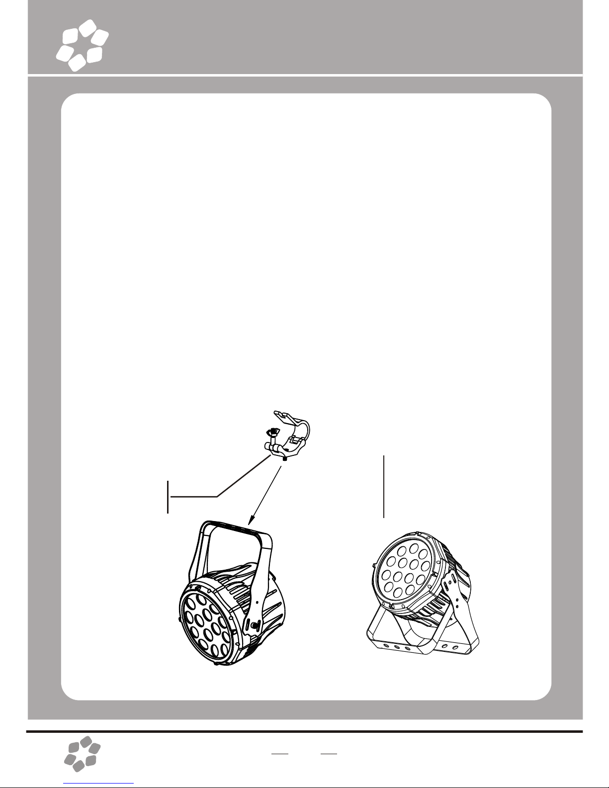
Operating instructions
1.Upload custom program or set to another machine
Set all thefixtures which receivecustom programs fromthe source fixtureas
1Press MODE buttonuntil is displayed.
2Then press ENTERbutton, use UP/DOWNbuttons until is displayed.
Press MODE returnto MENU
3On the Masterunit, Press MODEbutton until is displayed onsource fixture.
4Then press ENTERbutton, use UP/DOWNbuttons until is displayed.
5Then press ENTERbutton, Input passwordUP, UP, DOWN, DOWN,press
ENTER.All the lightsdisplay yellow color when uploading.After upload finish,it
will turns togreen which meansupload successful.If has mistake,it will turns
to red color.
6Press <MODE> onthe source unitto exit the upload mode.
2 Enable password lock
ÜON / OFF Ü{ENTER}
ON enable lock OFF disable lock
Enable the passwordlock, control panel in the boot or go into standby automatically
take effect, this time tooperate lamps needto enter yourpassword. { MODE UP
MODE DOWN MODE UP MODE DOWN }Ü{ENTER}
3 Factory reset
ÜÜ{UP UP DOWN DOWN}Ü{ENTER}
Note: The password is permanentlyset as {UP UP DOWN DOWN}
Then press ENTERbutton
4 Custom program
ÜÜ
1Press MODE buttonuntil is displayed, pressENTER access programmode.
2Select the programyou'll edit bypressing UP/DOWN buttons. The available
range is o1-10.
3Select the stepyou'll edit bypressing UP/DOWN buttons, and then press
ENTER button accessprogram.

11
When 'R000' displayon the screen,press the UP/DOWN button to choose the value.
Repeat this stepto edit thevalue of 'G000', 'b000','W000', 'S000', 'T000'and 'F000'.
Please pay attentionfor the 'S'is the rateof strobe. 'T'is the operatingtime of the
present step, thevalue is between0 to 255.'F' is thetransitional time fromprevious
step to presentstep. The transitional time isthe quickest whenthe FADEis 0.
Notice: Please operatethe program inturn, from the 01st step to the 30th step.
When the operatingprogram less than30 steps, please set the final step value be 0
4Repeat step 3till complete programming.
5Exit program modeby pressing MODEbuttons three times.
DMX512 Controller Mode
1 DMX operate mode setting
Access control panelfunction by pressingMODE until is displayed.
Press ENTER, pressUP/DOWN buttons until the is displayed.
Press ENTER, PressMODE return to MENU
2 Setting DMX512 Address
Ü001--512
Access control panelfunction by pressingMODE until is displayed.
Press ENTER, addor reduce channelsby pressing UP/DOWNbetween 001 and512.
Press MODE toexit.
3 Setting Channels
Ü
Access control panelfunction by prekssingMODE until is displayed.
Press ENTER button,select DMX channel by pressing UP/DOWN,
Press MODE toexit.

Channel
1 Dimming
2 RED
3 Green
4 Blue
5 white
6 Macro color
control
7 Strobe
8 auto &
custom program
Value
000~255
000~255
000~255
000~255
000~255
000~009
010~255
000~255
000~009
010~019
020~029
030~039
040~049
050~059
060~069
070~079
080~089
090~099
100~109
110~119
120~129
130~139
140~149
150~159
160~169
170~179
180~189
190~199
200~225
Description
0-100%
0-100%(Or STEP TIME whenCUS.01-10 is activated)
0-10 0%(Or FADE TIMEwhen CUS.01-10 isactivated)
0-100%
0-100%
No Function
Macro color control
Strobe(00~20Hz)
No Function
Out1 AUTO1
Out2 AUTO2
Out3 AUTO3
Out4 AUTO4
Out5 AUTO5
Out6 AUTO6
Out7 AUTO7
Out8 AUTO8
Out9 AUTO9
Out10 AUTO10
cust1 custom program1
Cust2 custom program2
Cust3 custom program3
Cust4 custom program4
Cust5 custom program5
Cust6 custom program6
Cust7 custom program7
Cust8 custom program8
Cust9 custom program9
Cust10 custom program10
DMX512 Channel Values
11 channels STAG
12

13
ID ADDRESS SELECTION
VALUE
000~009
010~019
020~029
030~039
040~049
050~059
060~069
070~079
080~089
090~099
100~109
110~119
120~129
130~139
140~149
150~159
160~169
170~179
180~189
190~199
200~209
210
211
FUNCTION
All Ids
ID1
ID2
ID3
ID4
ID5
ID6
ID7
ID8
ID9
ID10
ID11
ID12
ID13
ID14
ID15
ID16
ID17
ID18
ID19
ID20
ID21
ID22
VALUE
212
213
214
215
216
217
218
219
220
221
222
223
224
225
226
227
228
229
230
231
232
233
234
FUNCTION
ID23
ID24
ID25
ID26
ID27
ID28
ID29
ID30
ID31
ID32
ID33
ID34
ID35
ID36
ID37
ID38
ID39
ID40
ID41
ID42
ID43
ID44
Id45
VALUE
235
236
237
238
239
240
241
242
243
244
245
246
247
248
249
250
251
252
253
254
255
FUNCTION
ID46
ID47
ID48
ID49
ID50
ID51
ID52
ID53
ID54
ID55
ID56
ID57
ID58
ID59
ID60
ID61
ID62
ID63
ID64
ID65
ID66
Channel
9 Auto Speed
10 Dimming speed
11 ID
Value
000~255
000~255
000~255
Description
0~100%(only when using ch.8)
Dimming speed
ID address selection

14
MASTER DIMMER
Channels 1 controlsthe intensity of the currently projectedcolor
When the slideris at the highest position (255), then the intensityof the output is at
themaximum.
RED, GREEN BLUE AND WHITE COLOR SELECTION
Channels 2, 3,4and 5 control the intensity ratio of each of the Red, Green, Blue&white
LEDs.
1,2,3,4 and 5 channel can be used in combinationr
COLOR MACROS
Channel 6 selectsthe required Color Macro.
Channel 6 haspriority over Channels 2, 3,4& 5 .
Channel 1 isused to control the intensity of the current ColorMacro.
STROBE
Channel 7 controlsthe strobe of Channels 1 through 6.
Channel 7 haspriority over Channels 2, 3, 4 & 5.
Speed of thestrobe is adjustable from 0 to 20 Hz.
AUTO & CUSTOM PROGRAMS
Chanel 8 selectsthe preset Auto/Custom programs 1~10
When activating theAuto/Custom programs, it is thenpossible to controlthe Step time
and Fade timeby using Channels 2 & 3 respectively.
Channel 8 haspriority over channels 2-7.
DIMMER SPEED
Channel 10 isfor selecting the dimmer mode and dimmer speed.
When channel 10 is not activated, then RGBW and Master Dimmer arelinear.
The dimmer modes1, 2, 3, and 4 are different speeds of the nonlineardimming curves
ID ADDRESS SELECTION
Use channel 11 to selectID addressed fixtures.
Each independent DMXaddress can have up to 66 ID addressed fixtures.
ID address “0”allows control ofall fixtures simultaneously.

15
Note: In HSV mode,Hue stands forthe visible light, such as red, yellow, and
cyan, etc. Saturationrefers to the dominance of hue in the color; when saturation
is at 100%,then the coloris at its purest. Value is the color's brightness; when
value is at100%, then thecolor is at its brightest.
3 channels Co1
Channel
1
2
3
Value
000~255
000~255
000~255
Description
Red
Green
Blue
4 channels Co1.d
Channel
1
2
3
4
Value
000~255
000~255
000~255
000~255
Description
Dimming
Red
Green
Blue
4 channels Co2
Channel
1
2
3
4
Value
000~255
000~255
000~255
000~255
Description
Red
Green
Blue
White
Channel
1
2
3
Value
000~255
000~255
000~255
Description
Hue
Saturation
Value (Intensity)
3 channels HSV

16
6 channels Co2.s
Channel
1
2
3
4
5
6
Value
000~255
000~255
000~255
000~255
000~255
000~255
Description
Dimming
Red
Green
Blue
White
Strobe
ID Address Instructions
1.Setting ID address
1 Access control panelfunction by pressing MODE until is displayed.
2 Press ENTER, increase or reduce ID values by pressing UP/DOWN between 01
and 66.
3 Press MODE toexit.
2. Enable or disable ID
ÜÜON-OFF
1 Access control panel function by pressing MODE until is displayed.
2 Press ENTER, select by pressing UP/DOWN until is displayed.
3 Press ENTER, turn on oroff ID addressing by pressing UP/DOWN buttons.
4 Press MODE toexit.
For every DMX512 address the user can set 66 separate ID addresses. ID
addressing is a secondary function in DMX512 mode. In DMX512 Controller Mode,
the user can simultaneously control the individual DMX address of all lights, and
can control thelights which have separate ID address in independent DMX512.
5 channels Co2.d
Channel
1
2
3
4
5
Value
000~255
000~255
000~255
000~255
000~255
Description
Dimming
Red
Green
Blue
White

17
Select STAG channel on fixture's control panel (Please refer to DMX512
Channels Selection). The figure above shows a simple DMX layout which has
used three units at each DMX address. The three units have different ID
addresses. In the DMX address: 001,the user can control the firstthree lights
simultaneously. When using channel 11 select the channel number is 020-029
and ID Address=02, the controller can control the second light individually.
When using channel 11 select the channel number is 000-010 and ID
Address=00, all thelights are in common use at the same DMX address.

18
Master/Slave Control Mode
1 Setting master machine
Access control panelfunction by pressingMODE until is displayed.
Press ENTER, select or by pressing UP/DOWNbuttons.
Press ENTER, andthen press MODEto exit.
You can choose pre-set programs, therange is o1--10 .
Or you canchoose custom programs, therange is o1--10 .
2 Setting slave machine
Access control panel functionby pressing MODE until is displayed.
Press ENTER, pressUP/DOWN buttons until the is displayed.
Press MODE returnto MENU
3 Usage of Master/Slave
When two or more fixtures connected, you can set up the first machine asthe
Master and thefollowed fixtures asSlaves. The Master can choosepre-set programs ...
or , all theslaves will followthe Master's operationsynchronously.
5. APPENDIX
Service Maintenance Guide
Symptom(s)
1 or moreLED's are
not illuminating
Possible Solution(s)
Clean the fixtureregularly to avoidany such failure.This fixture is
convection cooled, whichmeans that ifthe surface iskept clean
and free ofdebris, then propercooling will beallowed to occur
An LED mayhave failed, resulting in an open circuit. In this event,
all of thered, green, or blue in a single module will no longer
illuminate. This does not meanthat all of the LEDs have failed,
but the circuitis wired in series.
An LED mayhave failed, resultingin a shortcircuit. In thisevent, only
the single LEDwhich has failedwill no longerfunction. This does not
mean that allof the LEDshave failed, butthe circuit iswired in series.
-Note: In theevent of LED failure, a replacementLED PCB
assembly may bepurchased directly from Our company

19
Symptom(s)
Breaker/Fuse keeps
blowing
Device has nopower
Fixture is not
responding to DMX
Loss of signal
COLOR-CON
Controller does not
function, or doesnot
function properly
Stand alone
operation
The display isonly
showing: ####
Possible Solution(s)
Check total loadplaced on the electrical circuit
Check for ashort in theelectrical wiring: internaland/or external
Check for poweron Mains
-Note: In theevent of autoswitching transformer failure, theunit
can be sentin for repair; however, a replacement part canbe
ordered directly from Our company
Check Control Panelsettings for correct addressing
Check DMX cables
Check polarity switchsettings on the controller
Check cable connections
Call service technician
-Note: In theevent of Display PCB failure, a replacement PCB
can be ordereddirectly from Our company
Use only DMXcables
Install terminator
Note: Keep DMXcables separated from power cables or black
lights
Make sure connectoris firmly connected to device
This fixture mustbe in the correct mode inorder to properly
respond to theCOLOR-CON controller. The correct mode is
“DMX” in the onboardControl Panel
This fixture hasbuilt-in, automatic programs that may be
triggered from theonboard Control Board
The password lockouthas been enabled. you can usethe
password: { MODE UP MODE DOWN MODE UP
MODE DOWN }

20
Blow-out Diagram.
1
2
3
4
5
6
7
8
9
10
11
12
13
Description
Glass cover
LED Lens assembly
LED Metal-core PCBassembly
Electronic Transformer
LED Driver PCB(Master)
Display PCB
Display Clear plasticcover
Display watertight seal
house
power socket
DMX socket
Bracket Assembly
Bracket adjustment metalknob
Part Number
6P00605
4170705
2P00603
5080102
2P00604
2P00605
803004
6P00613
6P00606
5050101
5040201
6P00611
5020118
Table of contents