Golden Technologies Buzzaround Extreme GB118EX User manual

Buzzaround Extreme
Service Guide
This Service Guide contains:
Troubleshooting
Replacement Instructions
Multi-meter Instructions
GB118EX GB148EX

2

3
Table of Contents
Nomenclature and Contact Information.........................................................................................................4
ABOUT THE BUZZAROUND EXTREME SERVICE GUIDE..................................................................5
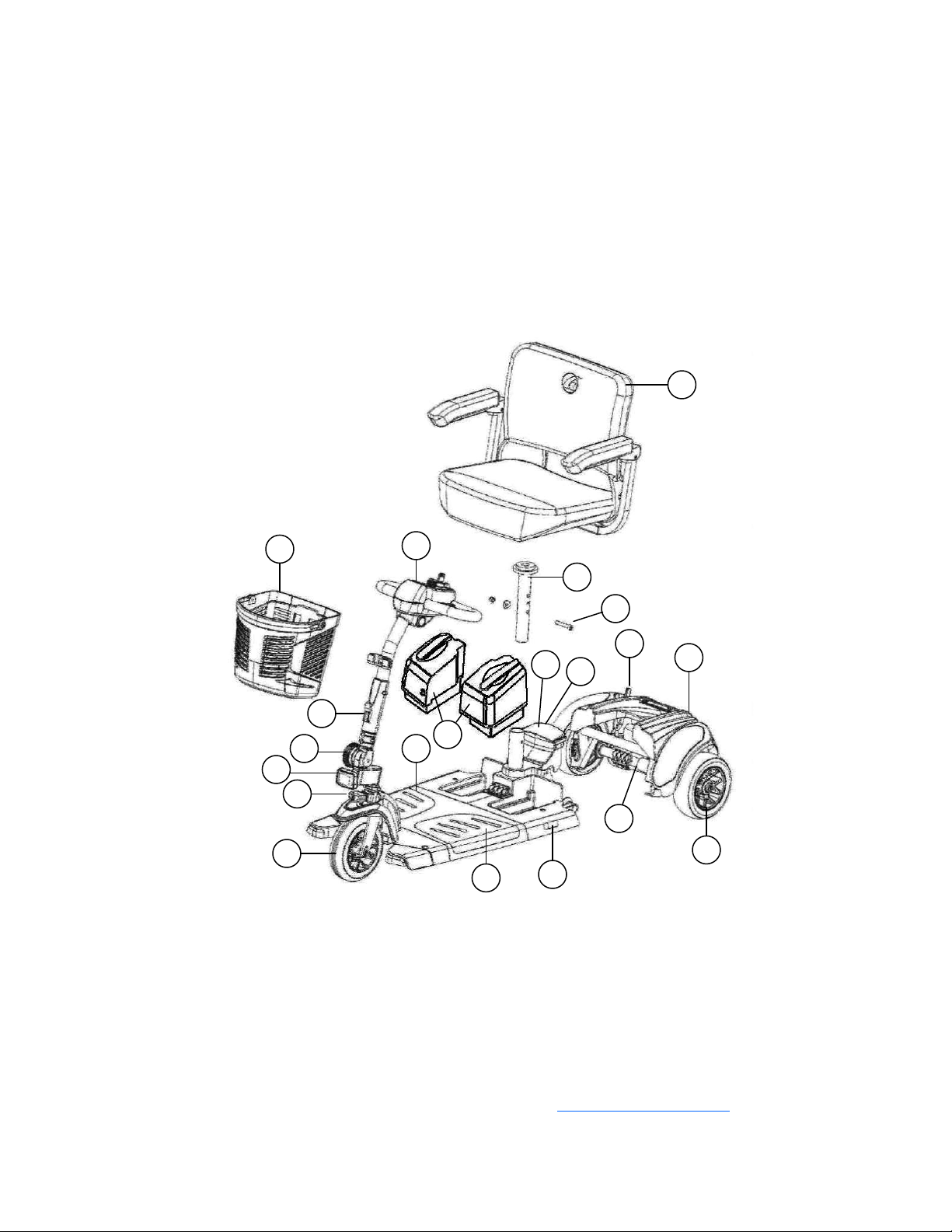
Buzzaround Extreme Components............................................................................................................5-10
Wiring Diagram.......................................................................................................................................11-12
SCENARIO 1: Turn the key to the on position and no power.....................................................................13
SCENARIO 2: Batteries will not charge......................................................................................................14
BEEP/FLASH CODES...........................................................................................................................15-20
BEEP/FLASH CODE #1 – Batteries Low (Scooter may drive slowly).......................................................15
BEEP/FLASH CODE #2 – Batteries Low (Scooter will not operate).........................................................15
BEEP/FLASH CODE #3 - High Battery Voltage........................................................................................15
BEEP/FLASH CODE #4 - Current Limit Timeout.................................................................................15-16
BEEP/FLASH CODE #5 - Brake Fault..................................................................................................16-17
BEEP/FLASH CODE #6 - Paddle Fault (out of neutral).............................................................................17
BEEP/FLASH CODE #7 - Paddle Fault/Speed Control Fault (voltage error)........................................18-19
BEEP/FLASH CODE #8 - Motor Voltage Fault (Open/Shorted)..........................................................19-20
BEEP/FLASH CODE #9 - Controller Fault.................................................................................................20
BUZZAROUND EXTREME REPLACEMENT INSTRUCTIONS......................................................21-27
Drive Wheel..................................................................................................................................................21
Drive Train....................................................................................................................................................21
Throttle Pot...................................................................................................................................................21
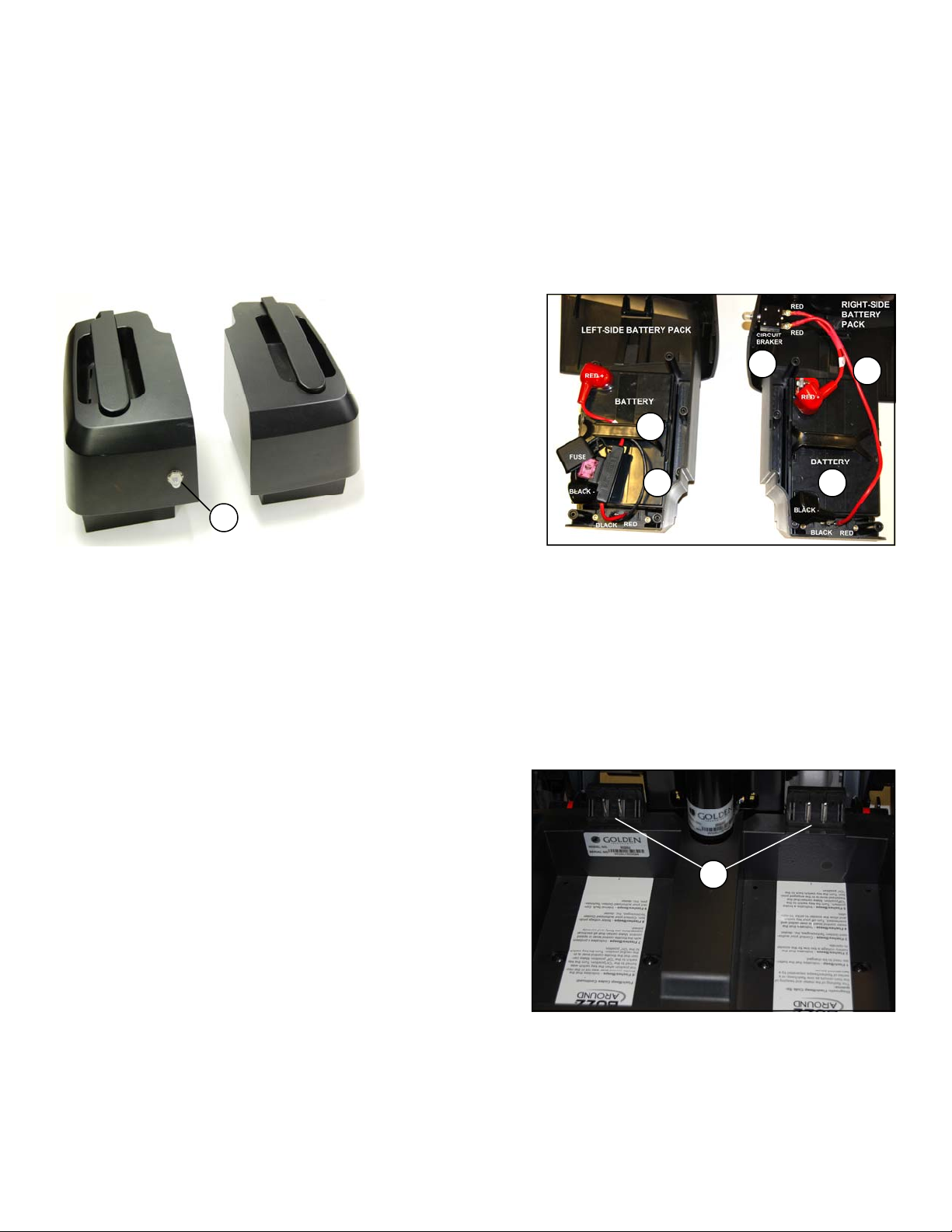
Battery...........................................................................................................................................................22
Circuit Breaker..............................................................................................................................................23
Battery Harness Fuse....................................................................................................................................23
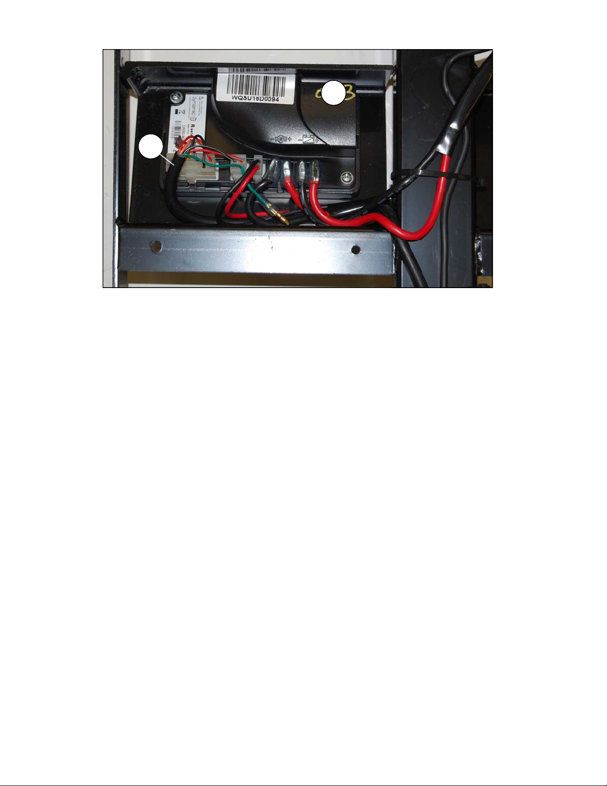
Controller......................................................................................................................................................23
Main Harness................................................................................................................................................24
Control Panel................................................................................................................................................24
Motor/Brake..................................................................................................................................................25
Front Intermediate Harness.....................................................................................................................25-26
Rear Intermediate Connector........................................................................................................................26
Power Harness..............................................................................................................................................27
APPENDIX A - HOW TO USE A VOLTMETER......................................................................................28
APPENDIX B - HOW TO USE AN OHM METER...................................................................................29

4
BUZZAROUND EXTREME NOMENCLATURE
Figure 1. Buzzaround Extreme (Model GB118EX)
1
2
3
10
4
5
6
7
8
9
11
12
13
14
15
16
1 - Seat Assembly with arms
2 - Control Panel
3 - Battery packs
4 - Rear Section
5 - Freewheel Lever
6 - Drive Wheel
7 - Front Section
8 - Controller (located under floor panel)
9 - Removable Anti-Slip Floor Panels (Gray/Textured)
10 - Front Wheel
11 - Tiller
12 - Front Basket
13 - Seat Post
14 - Bolt, Arc Washer, and Nut
15 - Lockup Handle
16 - LED Headlight
17 - Tiller Adjustment Knob
18 - Tiller Lock Knob
19 - LED Taillight
20 - Drive Train (Transaxle, Motor, and Brake)
17
18
19
Contact Information
Golden Technologies
401 Bridge Street
Old Forge, PA 18518
Toll-free: 800-624-6374
Mobility Tech: x501
Lift Chair: x502
VA Tech: x505
Fax: 800-628-5165
Email: [email protected]
20

5
This service guide provides you with the information necessary to troubleshoot the Golden Technologies
Buzzaround Extreme GB118EX/GB148EX. The troubleshooting scenarios in this manual consist of
procedures that enable you to systematically trace and correct faults in the system. Appendices A and B
include instructions on how to measure voltage and continuity with a multimeter.
Before troubleshooting, check the following:
Make sure that the circuit breaker is reset.
Visually check terminals for corrosion. Check wires for missing insulation.
Make sure the battery terminals are securely tightened.
Make sure that the batteries are fully charged and are in good working order. When possible, keep
sets of known good batteries of various ratings in your shop at all times. The Buzzaround Extreme
uses two (2) U1 batteries. Problems that surface during troubleshooting are often due to the fact that
the batteries are not fully charged or can not hold their charge.
Make sure that the electrical connections are secure. Unplug the connectors and make sure all the
pins in the connectors are seated securely. If necessary, push any unseated pins back into their con-
nector housings to securely seat them.
If you get to a point during troubleshooting where you cannot continue, call
Technical Support at 800-624-6374.
BUZZAROUND EXTREME COMPONENTS
The Buzzaround Extreme is a battery-operated scooter with a controller that monitors the system and beeps
when it detects a fault in the system. The Buzzaround Extreme was designed to operate within a range of
between 18 - 24 volts (V) of direct current (DC).
The Buzzaround Extreme control system is made up of the components listed below. Each
of these components is designated by its assigned number. Refer to the wiring diagram on page 11.
• Circuit Breaker (1)
• 12V Batteries (2 and 3)
• Battery Harnesses (4)
• Power Harness (5)
• Dynamics R-Series Controller (6)
• Main Harness (7)
• Front Intermediate Harness (8)
• Rear Intermediate Connector (9)
• Motor/Brake Assembly (10)
• Brake (11)
• Control Panel - includes Speed Pot (12), Key Switch (13), Horn Button, and Battery Meter
• Throttle Pot (14)
• Charger Harness (15)
• Off-Board Battery Charger – (Not shown)
Parts and service must be authorized by the Golden Technologies Service
Department. Unauthorized parts or service may void the warranty. For more information, contact the

6
Component: Circuit Breaker - #1
Location: Mounted on the right-side battery pack. See figure 2.
Function: Protects battery circuit from current overload. When the current draw exceeds the breaker rating, the circuit
breaker will open.
Connections: The circuit breaker is connected to the positive (+) terminal on one battery and the negative (-) terminal
on the other. (Note: Both circuit breaker wires are orange in color.)
Failure Signs: Opens repeatedly. May indicate failed circuit breaker or short in the wiring. May also open if the
motors are overloaded (from excessive weight, excessive uphill driving, etc).
Test: Measure the resistance across the circuit breaker and the wires that connect the circuit breaker to the batteries.
Expected reading: Less than 10 ohms.
Serviceable: 40 amp circuit breaker must be replaced with exact current rating.
Figure 2. Battery packs (Qty. 2) Figure 3. Inside Battery packs
Component: 2-12VDC Batteries - #2 and #3
Location: Inside the Battery packs. See figure 3.
Function: Supply 24VDC to the motor and/or accessories (12VDC x 2).
Connections: Connected in series. The positive (+) terminal of one battery is connected to the negative (-) of the
other (red wires) through the circuit breaker (1). The most positive and negative terminals are connected to the (red and
black wires) to the controller through the power harness (5). Refer to the wiring diagram on page 11.
Failure Signs: Batteries drain quickly. Scooter runs slowly or not at all. Batteries will not charge, but charger is
working properly. Beep Code #1 or #2.
Tests: Fully charge the batteries first and load test. Make sure the contacts are not corroded. See figure 4 below and
figure 16 on page 14.
Expected Readings: 12 - 14VDC each when fully charged.
Serviceable: Replace batteries as necessary.
Component: Battery Harness - #4
Location: Inside the Battery packs. See figure 3.
Function: Connects the batteries to the Power Harness (5).
Provides short circuit protection through a 100-amp inline fuse,
located on the left-side battery harness only.
Connections: Connected to the power harness, batteries, and
battery fuse. Refer to the wiring diagram on page 11.
Failure Signs: Corroded wires may cause the batteries not to
work properly. Make sure connector pins are seated properly.
Batteries will not charge if the inline fuse is blown. Figure 4. Scooter Battery Connection
Tests: Test the harness for continuity. Test the fuse for continuity.
Expected Readings: Less than 10 ohms.
Serviceable: Replace the harness as necessary. Replace inline fuse with exact type and rating. See figure 3.
5
2
3
4
CircuitBreaker
1
Right‐side
Left‐side
4
1

7
Figure 5. Controller
Component: Power Harness - #5
Location: Mounted to the front frame – located under the battery packs. See #5, figure 4 on page 6.
Function: Connects the Battery packs to the controller.
Connections: Connects the battery packs to the controller (Bat -) and (Bat +) connections.
Refer to the wiring diagram on page 11.
Failure Signs: Scooter will not power up. The controller is not receiving the correct battery voltage.
Tests: Test harnesses for continuity. Check connectors. Make sure the contacts are not corroded and are seated
properly. Slide a quarter into each of the four contacts to test the spring tension. Each one should retain the quarter, not
allowing it to fall out.
Expected Readings: Continuity (less than 10 ohms).
Serviceable: Replace as necessary.
Component: Controller - #6
Location: Mounted to the front frame - under the floor shroud. See #1 on figure 5.
Function: Controls and monitors the system. Uses a series of beeps/flashes when something in the system is out of
range.
Connections: Connected to the main harness, charger & inhibit, brake, motor (M-M+), battery (B-B+). See figure 5.
Refer to the wiring diagram on page 11.
Failure Signs: Beep Code #9. No power to the control panel or the motor.
Tests: Test for voltage coming into and out of the controller.
Expected readings: Battery voltage.
Serviceable: Replace as necessary.
Component: Main Harness - #7
Location: Inside the tiller and under the frame. See #2 on figure 5.
Function: Provides connectivity for the tiller components and the controller.
Connections: Connected to the controller, and control panel. Refer to the wiring diagram on page 11.
Failure Signs: Scooter will not run.
Tests: Test for voltage and continuity. Check connectors. Make sure the pins are not corroded and are seated properly.
Expected readings: Battery voltage. Continuity (less than 10 ohms).
Serviceable: Replace as necessary.
Main
Harness
Charger
& inhibit
Brake
M-
M+
Bat-
Bat+
1
2

8
Component: Front Intermediate Harness - #8
Location: Mounted on the front frame. See figure 6.
Function: Provides connectivity between the motor/brake
and the controller.
Connections: Connected to the rear intermediate connector (9)
and the controller (6). Refer to the wiring diagram on page 11.
Failure Signs: Scooter will run slowly or not at all.
Tests: Test for voltage and continuity. Check connectors.
Make sure the pins are not corroded and are seated properly.
Expected readings: Continuity (less than 10 ohms).
Serviceable: Replace as necessary.
Component: Rear Intermediate Connector - #9
Location: Mounted on the rear frame. See figure 7.
Function: Provides connectivity between the motor/brake Figure 6. Front Intermediate Harness
and the controller.
Connections: Connected to the front intermediate
harness (8) and the motor/brake assembly (10).
Refer to the wiring diagram on page 11.
Failure Signs: Scooter will run slowly or not at all.
Tests: Test for voltage and continuity. Check connectors.
Make sure the contacts are not corroded.
Expected readings: Continuity (less than 10 ohms).
Serviceable: Replace as necessary.
Component: Motor/Brake Assembly - #10
Location: Mounted on the transaxle. See #1 on figure 8.
Function: Drives the scooter.
Connections: Connected to the rear intermediate connector (9)
and the brake (11). Refer to the wiring diagram on page 11.
Failure Signs: Scooter runs slowly or not at all. Figure 7. Rear Intermediate Connector
Tests: Test for internal resistance in motor. Test motor
wires for continuity. See Beep Codes #5 and #8.
Expected readings: Internal motor resistance is
0.8 ohms – 1.5 ohms. Brake resistance is 45 ohms – 52 ohms.
Serviceable: Replace the motor/brake assembly.
Component: Brake - #11
Location: Mounted on the end of the motor. See #2 on figure 8.
Function: Keeps the motor from moving when the power is off.
Connections: Connected to the rear intermediate connector (9).
Refer to the wiring diagram on page 11.
Failure Signs: Scooter runs slowly or not at all.
Tests: Test for internal resistance. See Beep Code #5 on page 16
and Beep Code #8 on page 19.
Expected readings: Brake resistance is 45 ohms – 52 ohms.
Serviceable: Replace the motor/brake assembly.Figure 8. Motor/Brake Assembly
2
1

9
Component: Speed Pot (Potentiometer) - #12
Location: Mounted on the control panel. See #1 on figure 9.
Function: The speed pot uses variable resistance to control the
speed of the scooter.
Connections: Connected to the main harness through the control panel
harness.
Failure Signs: Beep Code #7
Tests: Call Tech Support
Expected readings: Depends on speed pot position.
Serviceable: Yes. Replace the speed pot.
Component: Key Switch - #13
Location: Mounted on the control panel. See #2 on figure 9.
Function: Completes the circuit to provide power to the motor.
Connections: Connected to the main harness through the
control panel harness.
Failure Signs: No power when the key is in the “ON” position.
Tests: Continuity when the key is in the “ON” position. Make
sure the connector pins are seated properly.
Expected readings: Less than 10 ohms.
Serviceable: Yes. Replace the key switch.
Component: Throttle Pot (Potentiometer) - #14 Figure 9. Control Panel (Back)
Location: Below the control panel. See #1 on figure 10.
Function: The throttle pot uses variable resistance
to control speed and direction of travel by varying voltage.
Connections: Connected to the main harness (7) and 1amp in-line fuse.
Refer to the wiring diagram on page 11.
Failure Signs: Beep Codes #6 and #7.
Tests: Test resistance across pins 1, 2, and 3 on the throttle pot.
Expected readings: Depends on direction of deflection.
Serviceable: Replace as necessary.
Component: Charger Harness - #15
Location: Left-side of tiller below the control panel. See #15 on figure 11
on page 11.
Function: Connects the charger to the batteries.
Connections: Connected to the controller (6), and the charger not shown.
Refer to the wiring diagram on page 11.
Failure Signs: Batteries will not charge.
Tests: Test for voltage and continuity. Check connectors.
Make sure the pins are not corroded and are seated properly.
Expected readings: Continuity (less than 10 ohms).
Serviceable: Replace the harness as necessary.
Figure 10. Throttle Pot
1
2
1

10
Component: Off-Board Charger (Not shown)
Location: Stored inside a pouch on the seatback.
Function: Recharges batteries.
Connections: Connects to the charger port on the tiller. Refer to
the wiring diagram on page 11.
Failure Signs: Charger power LED does not go on. Batteries
will not charge.
Tests: With the charger connected to the charger port, measure
voltage across the most negative (black wire) and most positive
(red wire) battery terminals. While observing the voltage reading,
plug the charger into the wall outlet and make sure the voltage
reading increases.
Expected readings: Battery voltage first, approximately 27 volts
when fully charged. Then voltage should increase to approximately
29.5 volts with the charger connected and plugged into the wall outlet.
Also, refer to the charger test on page 13. Test charger harness and
fuse for continuity.
Serviceable: Replace if necessary.
Only use the charge that was supplied with the scooter. The charger was specifically
designed and tested for the product it came with.
Some Off-Board Battery Chargers may have a switch that enables them to be used with either
110 VAC or 230 VAC. This switch is typically located on the end of the charger. Some may also have a removable
glass fuse. *Fuses must be replaced with exact type and rating.*

11
Figure 11. Buzzaround Extreme Wiring Diagram
Speed Pot (12)
Throttle Pot (14) Horn Switch
Battery Meter
To LED Lights
See (C18-075-01100)
on page 12.
Key Switch (13)
Horn
Charger Harness (15)
Battery (2)
12V
Battery (3)
12V
40 AMP
Circuit Breaker (1)
Dynamic R-Series
Controller (6)
Battery Harnesses (4)
Power Harness (5)
Main Harness (7)
Rear Intermediate Connector (9)
Brake (11) Motor / Brake
Assembly (10)
Front Intermediate Harness (8)
Fuse1A
Fuse10A
Fuse 100A
Note: Blinking red LED is the diagnostic
flash code indicator. (Purple wire)

12
Figure 11a. Buzzaround Extreme Wiring Diagram

13
SCENARIO 1: TURN THE KEY TO THE ON POSITION AND NO POWER
Put the key into the key switch and turn to the on position. There is no power to the control panel. The horn does not
work and the battery condition meter does not work. Battery voltage travels from the batteries, through the controller
and the key switch. The test below will verify that there is battery voltage at the batteries, the controller, the main
harness, and the key switch.
Make sure that the batteries are fully-charged and connected properly. Refer to the battery connection diagram inside
the battery packs. You can also refer to the wiring diagram on page 11. If the batteries will not charge, go to “Scenario
2: Batteries will not charge.”
If you are unsure of the correct way to measure
voltage or resistance, refer to Appendix A and B in this manual
before proceeding.
Check Battery Voltage at Battery packs.
1. Remove the battery packs.
2. Measure voltage across the two inside terminals on the connector
of each battery pack. See figure 12.
• 12VDC (or battery voltage on each pack?) - Go to the next step.
• More than 8VDC on each pack? - Try to recharge the batteries.
Load test and replace if necessary.
• 0VDC? - Check main circuit breaker (1) and battery
harnesses (4) for continuity.
Check Voltage at Power Harness.
3. Remove the two gray floor panels by pushing them up from
the underside of the scooter frame.
4. Remove the four screws fastening the floor shroud.
5. Disconnect the power harnesses (5) from the controller.
6. Reinstall the two battery packs.
7. Measure voltage across the red B+ and black B- wires. See figure 13.
• 24VDC (or battery voltage?) - Go to the next step.
• 0VDC? - Check power harness for continuity.
Replace as necessary.
Check Voltage Out of Controller.
8. Reconnect the power harness to the controller.
9. Insert the multimeter probes into the terminal with the red
wire (pin 7) and the terminal with the black wire (pin 13)
on the back of the main harness connector (7). See figure 14.
• 24VDC (or battery voltage?) - Go to the next step.
• 0VDC? - Replace the controller.
Check Voltage at Main Harness.
10. Open the control panel.
11. Disconnect the red key switch connector harness (13).
12. Measure voltage across the two pins on the male connector
(red and blue wires). See figure 15.
• 24VDC (or battery voltage?) - Check continuity across the
key switch. No continuity? – Replace key switch.
Continuity? - Replace the control panel.
• 0VDC? – Check the fuse for continuity. No continuity? –
Replace the 1 amp fuse. Refer to the wiring diagram on page 11.
Continuity? - Replace the main harness (7).
Red +
Red +

14
SCENARIO 2: BATTERIES WILL NOT CHARGE
Most battery chargers need to “see” at least 16VDC at the charger port. Otherwise, they may not send a charging
current to the batteries. This test will ensure that the battery voltage is making it to the charger port. You will need
to check battery voltage and wiring harness continuity inside the battery packs.
If you are unsure of the correct way to measure voltage or resistance, refer to Appendix A and B
in this manual before proceeding.
Check Battery Charger Voltage.
1. Separate the front and rear halves of the scooter.
2. Plug the charger into the charger port and then into a wall outlet.
3. Measure voltage across the two outside terminals on the back-side of battery harness connector (4). See figure 16
and figure 16a.
Does the voltage increase?
• Yes? - Load test the batteries and replace as necessary.
• No? - But there is voltage. If the voltage is lower than 16VDC, then replace the batteries. If the voltage is 16VDC
or greater, then replace the charger.
• No? - And there is no voltage. Open the right-side battery pack and check the circuit breaker, and battery
harness for continuity. Open the left-side battery pack and check the 100 amp fuse and battery harness for
continuity. Replace the individual components as necessary. If all continuity readings are good, go to the next step.
Figure 16. Connector 4
4. Open the control panel.
5. Check the charger harness (15) and fuse for continuity.
• Less than 10 ohms? – Go to the next step.
• Open? – Replace the 10 amp fuse or the charger harness as necessary. See figure 17. Also, refer to the wiring
diagram on page 11.
Figure 17. Charger Harness and Fuse
6. If both the charger harness and fuse continuity readings are correct, replace the main harness (7).
Figure 16a. Connector Close up
Outside Terminal Outside Terminal
Outside Terminal
Right-side
Outside Terminal
Left-side
10AmpFuse
ChargerHarness

15
BEEP/FLASH CODES
The controller uses audible beeps/flashes to indicate the status of the system. When the controller notices that there is
a malfunction in the system, it will beep/flash a code when the power is on. For example, when it beeps/flashes five
times and stops that indicates beep/flash code #5 – Brake Fault.
The following beep/flash codes are used to help diagnose system errors:
Beep/Flash Code #1 – Batteries Low (Scooter will operate)
Beep/Flash Code #2 – Batteries Very Low (Scooter will not operate)
Beep/Flash Code #3 – High Battery Voltage
Beep/Flash Code #4 – Current limit timeout
Beep/Flash Code #5 – Brake Fault
Beep/Flash Code #6 – Paddle Fault (out of neutral)
Beep/Flash Code #7 – Throttle Pot/Speed Pot Fault
Beep/Flash Code #8 – Motor Voltage Fault (Open/Shorted)
Beep/Flash Code #9 – Controller Fault
If you are unsure of the correct way to measure voltage or resistance, refer to Appendix A and B
in this manual before proceeding.
BEEP/FLASH CODE #1 – BATTERIES LOW (SCOOTER MAY DRIVE SLOWLY)
This Beep/Flash Code occurs when the battery voltage drops below a certain level. Recharge the batteries immediately.
If the batteries will not recharge, then load test them or refer to “Scenario 2: Batteries will not Charge”, on page 14.
BEEP/FLASH CODE #2 – BATTERIES LOW (SCOOTER WILL NOT OPERATE)
This Beep/Flash Code occurs when the battery voltage drops lower than Beep Code #1. Recharge the batteries
immediately. If the batteries will not recharge, load test them or refer to “Scenario 2: Batteries will not Charge”, on
page 14.
BEEP/FLASH CODE #3 - HIGH BATTERY VOLTAGE
This Beep/Flash Code occurs when the battery voltage climbs above 26VDC.
1. Insert the key into the key switch and turn it to the on position. Allow the battery level to drop. Do not allow the
battery voltage to fall into the red area on the battery meter.
2. Check the battery charger. Make sure it is an approved charger.
BEEP/FLASH CODE #4 - CURRENT LIMIT TIMEOUT
This Beep/Flash Code occurs when the motor has been exceeding its maximum current rating for too long. This may
be due to a faulty motor, poor battery condition, excessive uphill driving, or excessive weight. First turn off the scooter
and allow it to cool for ten minutes. If this does not work, use the following procedure.
Inspect Motor/Brake and Rear Intermediate Connector.
1. Remove the seat.
2. Remove the battery packs.
3. Separate the front and rear halves of the scooter, and inspect the connection between the motor/brake assembly (10)
and the rear intermediate connector (9). Is there visible damage, discolored or melted wires? Refer to the wiring
diagram on page 11.
• Yes? - Replace the motor/brake assembly or rear intermediate connector as necessary.
• No? - Go to the next step.
Check Motor Resistance at Motor.
4. Measure resistance across the two outside pins on connector (9)
that have the thick black wire and the thick red wire.
(Internal resistance of the motor). See figure 18.
• 0.8 ohms – 1.5 ohms but not shorted? – Go to the next step.
• Out of that range, or open? – Replace the motor/brake assembly.
Figure 18. Connector 9

16
Check for Continuity on the Front Intermediate Harness.
5. Remove the two gray floor panels by pushing them up from the underside of the scooter frame.
6. Remove the four screws fastening the floor shroud.
7. Disconnect the front intermediate harness (8) from the controller. Refer to the wiring diagram on page 11.
8. Make sure that the pins are not damaged or discolored. On the front intermediate harness, check the continuity
between the M- and M+ (thick black and red ) wires and the two outside pins on connector 8.
• 10 ohms or less? – Replace the controller.
• Open? – Go the next step.
9. Inspect the front intermediate harness (8) and rear intermediate connector (9). Refer to the wiring diagram on
page 11.
Are they discolored, corroded, or damaged?
• Yes? - Replace as necessary.
• No? - Go to the next step.
10. Take a quarter and slide into each contact
on the front intermediate harness connector (8). See figure 19.
Does each contact hold the quarter firmly in place?
• No? - Replace the front intermediate harness (8).
• Yes? - Go to the next step.
11. Check the rear intermediate connector (9) and the
motor/brake harnesses connected to connector (9).
• No damage or discoloration? – Replace the controller.
• Damaged or discolored? – Replace as necessary. Figure 19. Quarter Test (Connector 8)
BEEP/FLASH CODE #5 - BRAKE FAULT
This Beep/Flash Code occurs because the park brake release switch is active or the park brake may be faulty.
Check the Park Brake Position
1. Turn the key to the off position.
2. Disengage and then re-engage the park brake.
3. Turn the key to the on position. Did the beep code clear?
• Yes? - OK.
• No? - Go to the next step.
Check Park Brake Resistance at the Controller.
4. Remove the seat.
5. Remove the battery packs.
6. Remove the two gray floor panels by pushing them up
from the underside of the scooter frame.
7. Remove the four screws fastening the floor shroud.
8. Disconnect the (J3) connector of the front intermediate harness (8)
from the controller. Refer to the wiring diagram on page 11.
9. Make sure that the pins on J3 are seated properly. Measure resistance
across (J3) pin 1 and pin 2 on the front intermediate harness (8)
with the park brake engaged. See figure 20.
• 45 ohms – 52 ohms? – Replace the controller.
• Shorted or open? – Go to the next step.
Figure 20. Connector J3

17
Check for Continuity on the Front Intermediate Harness.
10. Separate the front and rear halves of the scooter.
11. Measure resistance from the connector (J3) pin 1 an pin 2 to the two middle pins on the connector of the front
intermediate harness (8).
• 10 ohms or less? – Go to the next step.
• Open? – Replace the front intermediate harness (8).
12. Inspect the front intermediate harness (8) and rear intermediate connector (9). Refer to the wiring diagram on
page 11.
Are they discolored, corroded, or damaged?
• Yes? - Replace harness(es) as necessary.
• No? - Go to the next step.
13. Take a quarter and slide into each contact on the front intermediate harness connector (8). See figure 19 on
page 16.
Does each contact hold the quarter firmly in place?
• No? - Replace the front intermediate harness (8).
• Yes? - Go to the next step.
Check Resistance at Park Brake.
14. Measure resistance across the two inside pins on the
rear intermediate harness connector (9) with park brake
engaged. See figure 21.
• 45 ohms – 52 ohms? – Replace the controller.
• Out of range? – Replace the motor/brake assembly.
• Open? – Check the connections at connector (9).
• Shorted? – Replace the motor/brake assembly.
Figure 21. Connector 9
BEEP/FLASH CODE #6 - PADDLE FAULT (OUT OF NEUTRAL)
This Beep/Flash Code means that the throttle control lever was not in the neutral position when the key is turned to the
on position.
1. Turn the key to the off position.
2. Make sure that the paddle pot is not obstructed and it can return to the neutral (center) position.
3. Move the throttle pot forward and then reverse. Make sure that it is not obstructed. Does it spring back to the neutral
position?
• Yes? – Go to the next step.
• No? – Check for obstructions. Adjust if necessary. Replace if the adjustment does not work or if there are no
obstructions.
4. Turn the key to the on position. Does the code return?
• No? – OK
• Yes? – Go to Beep CODE #7 to test the paddle pot.

18
BEEP/FLASH CODE #7 - THROTTLE POT/SPEED CONTROL FAULT
This Beep/Flash Code occurs because there is a fault with the throttle pot,
speed pot, or the associated wiring.
Check Throttle Pot Resistance at Controller.
1. Remove the seat.
2. Remove the battery packs.
3. Remove the two gray floor panels by pushing them up
from the underside of the scooter frame.
4. Remove the four screws fastening the floor shroud.
5. Turn the speed pot to full rabbit.
6. Set your multimeter to measure resistance.
7. Disconnect the main harness (7) from the
controller. Refer to the wiring diagram on page 11.
8. Insert multimeter probes into the main harness Figure 22. Connector 7
connector 7 at pin 8 and pin 2 (orange wire and yellow wire).
See figure 22.
• 5k ohm ±10%? – Replace the controller.
• Outside that range? - Go to the next step.
9. Insert the multimeter probes into the main
harness connector 7 at pin 1 and pin 8
(gray wire and orange wire). See figure 23.
Note the resistance reading. Insert the multimeter probe
into the main harness connector at pin 1 and pin 2
(gray wire and yellow wire). See figure 24.
Note the resistance reading.
• Are both readings within 500 ohms of each Figure 23. Connector 7
other? - Replace the controller.
• Are either of the readings outside that range? - Go
to the next step.
Check Throttle Pot Resistance at Throttle Pot.
10. Open the control panel.
11. Disconnect the main harness (7) from
the throttle pot (14). Note: This is a red connector
with three wires, yellow, white, and orange.
Refer to the wiring diagram on page 11.
12. Insert multimeter probes into the throttle pot Figure 24. Connector 7
connector (14) at the yellow wire and the orange
wire (outside two pins). See figure 25.
• 5k ohm ±10%? - go to the next step.
• Outside that range? - Replace the throttle pot.
Figure 25. Connector 14

19
13. Insert the multimeter probes into the throttle pot
connector (14) at the orange wire and the white wire.
See figure 26. Note the resistance reading.
Insert the multimeter probes into the
throttle pot connector (14) at the yellow wire
and the white wire. See figure 27. Note the resistance reading.
• Are both readings within 500 ohms of
each other? - Go to the next step.
• Are either of the readings outside that
range? – Replace the throttle pot. Figure 26. Connector 14
14. Check the orange, gray, and yellow wires on
the main harness (7) for continuity.
• 10 ohms or less on each one? - Replace the
speed pot.
• Open on any wire? - Replace the main harness.
BEEP/FLASH CODE #8 - MOTOR VOLTAGE FAULT (OPEN)
This Beep/Flash Code occurs when there is an internal problem
with the motor or its wiring.
Check Motor Resistance at Controller. Figure 27. Connector 14
1. Remove the seat.
2. Remove the battery packs.
3. Remove the two gray floor panels by pushing them up
from the underside of the scooter frame.
4. Remove the four screws fastening the floor shroud.
5. Disconnect the (M- and M+) connections on the
front intermediate harness (8) from the controller.
Refer to the wiring diagram on page 11.
6. Measure resistance across the front intermediate
harness (M- and M+). See figure 28.
• 45 ohms – 52 ohms? – replace the controller.
• Out of that range? – Go to the next step.
Check for Continuity on the Front Intermediate Harness.
7. Separate the front and rear halves of the scooter.
8. Inspect the front intermediate harness connector (8).
Discolored, corroded, or damaged?
• Yes? - Replace as necessary.
• No? - Go to the next step.
9. Check the continuity between M- and connector 8, Figure 28. Connectors M-M+, J3, and 8
and M+ and connector 8.
Refer to the wiring diagram on page 11.
• 10 ohms or less? – Go to the next step.
• Open? – Replace the front intermediate harness (8).
10. Take a quarter and slide into each contact on the front intermediate harness connector (8). See figure 19 on
page 16.
Does each contact hold the quarter firmly in place?
• No? - Replace the front intermediate harness (8).
• Yes? - Go to the next step.

20
Check Motor Resistance at Motor.
11. Measure resistance across the two outside pins on connector (9) that have the thick black wire and the thick
red wire. (Internal resistance of the motor). See figure 29.
• 0.8 ohms – 1.5 ohms? – Replace the controller.
• Out of range? – Replace the motor/brake assembly.
• Open? – Check the connections at connector (9).
• Shorted? – Replace the motor/brake assembly.
BEEP/FLASH CODE #9 - CONTROLLER FAULT
This Beep/Flash Code means that the controller has an internal fault.
1. Remove the key from the key switch and allow
the controller to cool down. If the code continues,
then replace the controller.
Figure 29. Connector 9
This manual suits for next models
1
Table of contents
Other Golden Technologies Mobility Aid manuals
Popular Mobility Aid manuals by other brands

Mobilex
Mobilex DYNAWALK 313002 user manual

Drive Medical
Drive Medical i-walker user manual

lifestyle mobility aids
lifestyle mobility aids H6500H manual

Pharmaquip Healthcare
Pharmaquip Healthcare RCN0501BL manual

EZee Life
EZee Life CRP0100 quick start guide

NRS Healthcare
NRS Healthcare M48465 User instructions

Darco
Darco FX Pro Instructions for use

Ossenberg
Ossenberg 722P Instructions for use

iWALKFree
iWALKFree iWALK 2.0 user guide

My Child
My Child IM-151122-V3 instruction manual

Lumex
Lumex FREEDOM 80500 user manual

Direct Healthcare Group
Direct Healthcare Group SystemRoMedic BureDouble 2.0 Instructions for use