Golden JS-1500R User manual

17611 East St, North Fort Myers, FL 33917
(239) 337-4141
GoldenMarineSystems.com GoldenBoatLifts.com
REVISION A
PUBLISHED 10/18/2020
INSTALLATION
MANUAL
MODELS:
JS-1500R
SWINGER LIFT

2
TABLE OF CONTENTS
TABLE OF CONTENTS............................................................................. 2
INTRODUCTION & FEATURES............................................................... 2
SAFETY REQUIREMENTS....................................................................... 3
SPECIFICATIONS………………………….………………………………………………………….4
PART IDENTIFICATION TABLE..............................................................5
REQUIRED PARTS & HARDWARE ....................................................... 6
GENERAL ASSEMBLY ............................................................................ 7
SWINGER LIFT MOUNT LOCATION...................................................... 7
ATTACH PILING MOUNT......................................................................... 8
ATTACH SEAWALL MOUNT................................................................... 9
MOUNT MAST & MAST HOUSING .......................................................10
ATTACH CRADLE ARMS & CABLE ......................................................11
MOUNT BUNK BRACKETS....................................................................12
MOUNT BUNKS .......................................................................................13
MOUNT SEADRIVE………………………………………………………………………………….14
MOUNT MOTOR……………………………………………………………………………………….15
REFERENCE NOTES .............................................................................16
INTRODUCTION
We at Golden are proud to introduce the Swinger Lift to our
line of lifts.
The Swinger Lift is designed to easily lower small vessels
into the water directly off a seawall or dock.
This mounted lift is manufactured with T-6 marine grade
aluminum and stainless-steel hardware. This lift is ideal for
freshwater and saltwater applications and requires no shore
power.
The Swinger Lift was intentionally engineered to minimize
the space needed to operate the lift, making it extremely
versatile for many applications.
All non-adjustable components for the JS-1500R Swinger
Lift are welded together, decreasing premature loosening of
parts.
We use only eco-friendly biodegradable fluid. It is 100 %
water soluble and meets the strict guidelines of the US Fish
& Wildlife Service as non-toxic.
FEATURES
•Simple Installation Procedure
•Seawall and Piling Mount Options Available
•Welded 6061-T6 Marine Grade Aluminum Frame / 300
Series Stainless Steel Hardware and Cables
•13′or 15′Travel Distance Options Available (3.9m or
4.5m)
•Adjustable Bunks for Varying PWC Width
•Adapts to Fluctuating Water Levels
•Brake Winch Controls Up-And-Down Movement
•Grab Rails Provide Stability During Boarding
•Standard and XW Models Support JS-1500R Swingers
Up To 250 Pounds (113 kg)
•Supports PWC’s Up To 1,500 Pounds (680 kg)
SWINGER LIFT (Pile Mount)

3
SAFETY
SAFETY INFORMATION
(READ THOROUGHLY)
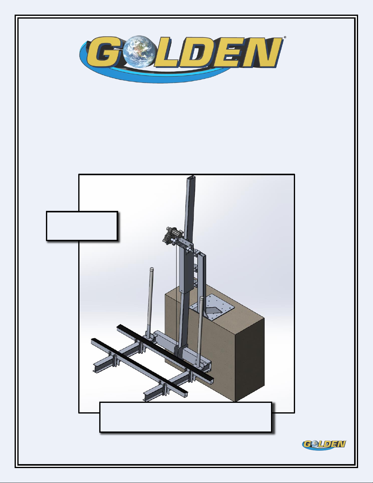
The JS-1500R PWC (Personal Water Craft) Swinger Lift was
designed, tested and certified to be installed in the
recommended area approved by certified and approved
personnel under the specific installation and operation
guidelines laid out in the installation and operation manuals
issued by GOLDEN BOAT LIFTS.
Note: Any installation or operation methods outside the
guidelines described within the manual(s) mentioned above
will void the product warranty.
Note: It is recommended that a trained professional install the
JS-1500R Swinger Lift.
Note: Before beginning installation of the Swinger Lift, please
ensure that the area selected for installation meets all local
and state guidelines and regulations.
Note: To avoid damage to the lift and/or personal injury/death,
carefully follow each step outlined in the manual(s).
Note: Before beginning installation of the Swinger Lift clear
adequate space around the installation site so that all parts,
hardware, and tools can be laid out in a safe and organized
fashion.
When completing the steps outlined in this Installation Manual,
please ensure that only proper handling and lifting techniques
are used to transport parts to desired locations. In some
circumstances, machinery may be required to move individual
parts.
The Swinger Lift comes with a RBC DC 3/4 HP 1725 RPM motor
which provides the power for operation of the Swinger Lift.
Note: After installation of the Swinger Lift, please reference
the motor manufacturer manual(s) to continue installation of
the power supply for the Swinger Lift. Failure to reference and
follow these instructions before attempting to operate the
Swinger Lift may cause damage to the lift and/or personal
injury/death.
After completing the steps outlined in the JS-1500R SWINGER
INSTALLATION MANUAL, the Swinger Lift should be ready to
operate.
Note: Before operation, it is important to verify that every step
outlined in the JS-1500R SWINGER INSTALLATION MANUAL.
Note: Never Exceed the maximum capacity of the lift.
Note: Never go under the lift or vessel, especially when the lift
is in the raised position. Never operate a lift while on the lift
or inside the vessel.
Note: It is recommended that the Swinger Lift be raised to the
upward position when not in use.
SAVE THESE SAFETY INSTRUCTIONS
FOR FUTURE REFERENCE
WARNING
!
!
MOVING PARTS HAZARD
Failure to follow this warning can result in personal injury or
death and/or damage to the Swinger Lift.
The Swinger Lift has moving parts while in operation. To avoid
bodily harm and/or damage to the Swinger Lift, ensure the lift
is operated from the dock or seawall, and never on the lift or
vessel.
Note: Never operate a lift while on the lift or
inside the vessel.
caution
!
!
HEAVY OBJECTS
Failure to follow this warning can result in personal injury or
death and/or damage to the Swinger Lift.
The Swinger Lift has heavy parts. To avoid bodily harm and/or
damage to the Swinger Lift, ensure that proper handling and
lifting techniques are used.
SAVE THESE INSTRUCTIONS

4
JS-1500R
1
2
3
4
5
6
7
8
9
10
11
CAPACITY MAST
MAST
HOUSING
ASSEMBLY
MOUNTING
BRACKET(S)
PILING
MOUNT
SEAWALL
MOUNT
CABLE
GUIDEPOST(S)
BUNK(S)
BUNK
BRACKET
CRADLE
BEAM(S)
CRADLE
ARM(S)
1,500 lb.
(680 kg)
STANDARD
4 X 6 X 156”
1/4 X 5 X 10”
ALUMINUM
TUBE
ALUMINUM
1.72 X 4”
/.320”
ALUMINUM
CHANNEL
ALUMINUM
1/4" DIA.
SS
DOUBLE
PULL
1.5” SCH. 40
ALUMINUM
2 X 8 X
96”
2 X 2 X .25”
ALUMINUM
ANGLE
4 X 8 X .25”
ALUMINUM
TUBE
4.03 X 4 X
6”
ALUMINUM
I-BEAM
EXTENDED
4 X 6 X 180”

5
PART IDENTIFICATION
MAST
QTY: ( 1 )
MAST HOUSING
QTY: ( 1 )
3/4 HP MOTOR
QTY: ( 1 )
SEA-DRIVE
QTY: ( 1 )
BUNK
QTY: ( 1 )
CRADLE ARM
QTY: ( 2 )
RETURN ROLLER
QTY: ( 1 )
PILING MOUNT
QTY: ( 1 )
*PILE MOUNTED
SEAWALL MOUNT
QTY: ( 1 )
*SEAWALL MOUNTED
BUNK MOUNT BRACKET
QTY: ( 8 )

6
HARDWARE (cont.)
REQUIRED TOOLS
9/16” Open End Wrench
3/4” Open End Wrench
15/16” Open End Wrench
3/8” Drive Ratchet
9/16” Socket
3/4” Socket
15/16” Socket
Hex Bolt QTY:
3/8” X 1” (5)
1/2” X 1-1/2” (4)
1/2” X 2-1/2” (2)
1/2” X 4-1/2” (2)
1/2” X 5” (5)
5/8” X 4-1/2” (4)
3/4” X 5” (1)
5/8” x 4-1/4” (w/ pin) (1)
Flat Washer QTY:
3/8” (9)
1/2" (10)
5/8” (11)
3/4" (3)
Lock Washer QTY:
3/8” (5)
1/2” (10)
5/8” (5)
3/4" (2)
Lag Bolt QTY:
5/8” X 4”
(5)
Finish Nut QTY:
3/8” (5)
1/2" (10)
5/8” (5)
3/4" (2)
Power Drill
**5/8” Auger Drill Bit
Nylon Washer QTY:
3/4” (6)
HARDWARE
MAST STOP PIN QTY:
1/2" X 6-1/2” (1)
COTTER PIN QTY:
1/8” (2)

7
GENERAL ASSEMBLY INSTRUCTIONS
1. Please read all instruction provided before starting
the installation of the JS-1500R Swinger Lift.
2. It is recommended that the Swinger Lift is installed
by trained professionals only.
3. Please ensure that there is an appropriate area
cleared in order to lay out all components, parts,
and applicable tools to ensure there is nothing
missing or damaged before starting installation
process.
NOTE: Inspect all pulleys, verifying all cables are laying
evenly in grooves.
NOTE: Ensure the drill bit is aligned correctly to avoid
drilling holes at an angle as this may cause damage to the
piling or lift.
SWINGER LIFT LOCATION PREP
(Mounting on Piling)
1. Measure the height from the top of the dock decking
to the top of the piling; the height must be a
minimum of 50” to ensure proper rotation of the
cradle(s).
2. Using the three (3) holes on the inside face of the
PILE MOUNT channel, align and mark the hole
locations on the pile.
NOTE: PILE MOUNT should be positioned on either side of
the pile, not on the dock or water side.
3. Using the 5/8” Auger Bit, drill completely through
the piling at the 3 marked locations.
SWINGER LIFT LOCATION PREP
(Mounting on Seawall)
1. Place the SEAWALL MOUNT in the desired location
and measure the area around the mount to ensure
there is adequate space for Swinger Lift to rotate
and operate.
NOTE: SEAWALL MOUNT should be positioned away from
any objects or structures that may interfere with
operation or movement. Additionally, make sure the
water depth meets recommended levels for the PWC.
REQUIRED PARTS (Seawall)
SEAWALL MOUNT
QTY: ( 1 )
REQUIRED PARTS (Piling)
PILE MOUNT
QTY: ( 1 )

8
ATTACH MOUNT (Piling)
1. Using three (3) 5/8” Bolts (not included), secure the
mount to the piling by inserting an appropriate bolt
through each of the three (3) holes in the piling
mount, and completely through the piling, as shown
in figure 1.
2. Fasten appropriate hardware to the protruding ends
of the mounting bolts and hand tighten to allow for
adjustments.
NOTE: Ensure the PILE MOUNT is square and plumb to the
piling; adjustments may be required to achieve desired
alignment.
3. Fully tighten mounting hardware using appropriate
tools.
4. Using the four (4) 5/8” x 4” Lag Bolts provided,
secure the four tabs at the top and bottom of the
PILE MOUNT to the piling.
Figure 2
Figure 1
REQUIRED PARTS (Piling)
PILE MOUNT
QTY: ( 1 )
HARDWARE
QTY:
Pile Mount
Hardware
(not included)
3
5/8 X 4” Lag Bolts
4
5/8" Washer
4

9
REQUIRED PARTS (Seawall)
SEAWALL MOUNT
QTY: ( 1 )
HARDWARE
QTY:
3/4" Seawall
Mount Hardware
(not included)
4
1/2" Seawall
Mount Hardware
(not included)
14
ATTACH MOUNT (Seawall)
NOTE: It is recommended to use more than one person for
this step to ensure the lift stays upright at all times.
NOTE: it is recommended to have a trained professional
pre-drill the SEAWALL MOUNT holes into the seawall to
avoid causing damage to the seawall or lift.
1. Using four (4) 3/4” Bolts (not included), secure the
mount to the seawall by inserting an appropriate
bolt through each of the four (4) 3/4" holes in the
SEAWALL MOUNT.
2. Using fourteen (14) 1/2” Bolts (not included), secure
the mount to the seawall by inserting an appropriate
bolt through each of the fourteen (14) 1/2" holes in
the SEAWALL MOUNT.
NOTE: Ensure the SEAWALL MOUNT is square and plumb
to the seawall; adjustments may be required to achieve
desired alignment.
3. Fully tighten mounting hardware using appropriate
tools.
Figure 3
Figure 4

10
MOUNT MAST & MAST HOUSING
NOTE: From the remaining steps, the PILING
MOUNT/SEAWALL MOUNT will be referred to as “MOUNT”
1. Insert the MAST into the MAST HOUSING with the
four holes in the MAST oriented toward the bottom.
NOTE: The Cable Roller should be oriented toward the top
of the MAST.
2. Stand the MAST and MAST HOUSING upright and
position as close to the BASE MOUNT as possible.
3. Align the swivel hinges on the housing above the
hinges on the BASE MOUNT and insert 3 Nylon
Washers between the hinges on the BASE MOUNT
and the housing as shown in figure 4.
4. Slip one (1) flat washer over each of the three (3)
5/8” X 4-1/2” bolts and insert through each of the
three (3) hinges as shown in figure 4.
5. Slip a 5/8" Lock Washer, 5/8" Washer and 5/8" Hex
Nut onto the protruding end of the bolt and securely
fasten.
6. Insert the 1/2" X 6-1/2” MAST STOP PIN into the hole
located at the top of the MAST and slip one (1) 1/2"
washer on either side of the pin as shown in figure
3.
7. Insert one (1) Cotter Pin one each side of the MAST
STOP PIN, making sure to spread the ends of the
COTTER PIN outward, securing the pin and washers
in place (THIS KEEPS THE LIFT FROM
OVERTRAVELING WHEN IN USE).
REQUIRED PARTS
HARDWARE
QTY:
5/8” x 4-1/2" Hex
Bolt
3
5/8" Lock Nut
3
5/8” Washer
6
1/2" Washer
2
3/4" Nylatron
Washer
6
Mast Stop Pin
1
Cotter Pin
2
Mast Housing
QTY: (1)
Mast
QTY: (1)
Figure 5
Figure 6

11
ATTACH CRADLE ARMS &
CABLE
1. Align the four (4) holes in both CRADLE mounting
plates with the four (4) holes on each side of the
lower MAST .
2. Slip one (1) 1/2" Washer over one (1) 1/2" X 5” Hex Bolt,
and insert it through the CRADLE mounting plates
and MAST.
3. Slip one (1) 1/2" Washer, one (1) 1/2" Lock Washer, and
one (1) 1/2" Hex Nuts onto the protruding end of the
bold and securely fasten; repeat for the remaining 3
bolts as shown in figure 7.
4. Slide the CABLE ROLLER between the mounting
plates in front of the MAST and align the holes
accordingly.
NOTE: Ensure the cable is hanging down on the outside of
the CABLE ROLLER
5. Slip one (1) 3/4" Washer over a 3/4" X 5” Hex Bolt and
insert it through the plate and roller.
6. Slip one (1) 3/4" Washer, one (1) 3/4" Lock Washer,
and one (1) 3/4" Hex Nuts onto the protruding end of
the bolt and securely fasten.
7. Wrap the cable around the CABLE ROLLER and bring
back upward between the CABLE ROLLER and the
MAST. Attach the end of the cable to the D-SHACKLE
at the lower end of the MAST HOUSING as shown in
figure 8.
REQUIRED PARTS
HARDWARE
QTY:
1/2” x 5" Hex Bolt
4
3/4" x 5" Hex Bolt
1
1/2" Hex Nut
4
3/4" Hex Nut
1
1/2" Lock Washer
4
3/4" Lock Washer
1
1/2" Washer
8
3/4" Washer
2
Figure 8
CRADLE
QTY: ( 2 )
Attach Cable
Figure 7

12
MOUNTING BUNK BRACKETS
1. Position the brackets so that the side with the single
hole is oriented upwards. Align the brackets so that
all the holes align with the holes on the other
bracket(s) as shown in figure(s) 9 & 10.
2. Position the four (4) brackets around the CRADLE,
making sure the side(s) with one (1) hole are
oriented upward and running parallel to the cradle;
the sides with two (2) holes should be running
across the top and bottom the CRADLE as shown in
figure 10. Repeat for the other three sets of brackets.
3. Slip one (1) Washer over one (1) 3/8” X 5-1/2” Hex Bolt
and insert it into the top hole on the bracket side
with two (2) holes. Repeat seven (7) times for other
bracket sets.
4. Slip one (1) 3/8" Washer, one (1) 3/8" Lock Washer,
and one (1) 3/8" Hex Nuts onto the protruding end of
the bold and hand tighten; repeat for the remaining
seven (7) bolts.
5. Repeat steps 3 & 4 for the lower hole on the
brackets.
NOTE: The bolts should be sitting on top and underneath
the CRADLE(s).
Bunk Bracket
QTY: 2
REQUIRED PARTS
HARDWARE
QTY:
3/8” X 5-1/2” Hex
Bolt
8
3/8” Hex Nut
8
3/8” Lock Washer
8
3/8” Washer
16
Figure 9
Figure 10

13
MOUNTING BUNKS
1. Sliding the connected brackets away from each
other, position the BUNK between two (2) sets of
brackets so that the single hole in the brackets are
aligned with the single hole on the bunk for each set
as shown in figure 11.
2. Slip one (1) Washer over one (1) 3/8” X 4”” Hex Bolt
and insert it into the hole on the bracket side facing
the BUNK Repeat seven (7) times for other bracket
sets.
3. Slip one (1) 3/8" Washer, one (1) 3/8" Lock Washer,
and one (1) 3/8" Hex Nuts onto the protruding end of
the bolt and securely fasten; repeat for the
remaining seven (7) bolts.
4. Slide the BUNKS along the CRADLES to desired
location and securely fasten all BUNK BRACKET and
BUNK hardware.
NOTE: Verify with your PWC manufacture about proper
BUNK positioning to avoid damage or personal injury.
Figure 11
Figure 12
REQUIRED PARTS
Bunk
QTY: 2
HARDWARE
QTY:
3/8” X 4” Hex Bolt
8
3/8” Hex Nut
8
3/8” Lock Washer
8
3/8” Washer
16

14
SEA-DRIVE INSTALLATION
1. Insert the drive shaft into the cable spool shaft,
making sure the holes in both shafts are aligned
properly to allow for hardware.
2. Rotate the SEA DRIVE so the motor mounting flange
is in the upright position as shown in figure 13.
3. Slip one (1) 1/2" Washer over one (1) 1/2” X 2-1/2”” Hex
Bolt and insert it into the hole in the spool shaft,
making sure the bolt goes through the drive shaft.
4. Slip one (1) 1/2" Washer, one (1) 1/2" Lock Washer, and
one (1) 1/2" Hex Nuts onto the protruding end of the
bolt and securely fasten.
5. Rotate the SEADRIVE so the motor mounting flange
is oriented upward; this should align the rear-drive
mount tab with the torque angle tube as shown in
figure 14.
6. Slip one (1) 1/2" Washer over one (1) 1/2” X 4-1/2”” Hex
Bolt and insert it into the hole in the spool shaft,
making sure the bolt goes through the rear-drive
mount tab and the torque angle tube.
7. Slip one (1) 1/2" Washer, one (1) 1/2" Lock Washer, and
one (1) 1/2" Hex Nuts onto the protruding end of the
bolt and securely fasten.
REQUIRED PARTS
HARDWARE
QTY:
1/2" X 2-1/2”Bolt
1
1/2" X 4-1/2”Bolt
1
1/2” Hex Nut
2
1/2” Lock Washer
2
1/2” Washer
4
Figure 13
Figure 14
Mini Sea Drive
QTY: 1

15
MOTOR INSTALLATION
1. Align keyway in motor shaft with key slot in the
motor mount flange and insert completely until flush
against motor.
NOTE: Lubrication may be needed for a smooth and proper
insertion; DO NOT use force to insert motor, as this may
cause damage to system.
2. Rotate motor so that capacitor cover is oriented
upward and the four holes in the motor housing align
with the four holes in the flange as shown in figure
15.
3. Slip one (1) 3/8" Lock Washer over one (1) 3/8” X 1”
Hex Bolt and insert it through the hole in the motor
mount and into the threaded hole in the flange and
securely fasten.
NOTE: Golden Boat Lifts recommends that a licensed
electrician wire and install the electrical components on
the Swinger Lift. Failure to follow this recommendation
may lead to injury, death, or damage to the lift.
NOTE: Please contact the remote-control manufacturer
for detailed instructions on setting up your remote and
operating the motor.
REQUIRED PARTS
HARDWARE
QTY:
3/8” X 1” Hex Bolt
4
3/8” Lock Washer
4
Figure 15
3/4 HP Motor
QTY: 1

16
REFERENCE NOTES
JS-1500R SWINGER LIFT PILING ☐SEAWALL ☐
INSTALLATION PROVIDER: ___________________________________________________ INSTALLATION DATE: _________________________
INSTALLATION ADDRESS: _______________________________________________________________________________________________________
INSTALLATION CHECKLIST:
STEP
DATE/TIME
INITIAL
NOTES
SAFETY REQUIREMENTS
PART IDENTIFICATION TABLE
REQUIRED PARTS & HARDWARE
SWINGER LIFT MOUNT LOCATION
ATTACH MOUNT (PILING/SEAWALL)
MOUNT MAST & MAST HOUSING
ATTACH CRADLE ARMS & CABLE
MOUNT BUNK BRACKETS
MOUNT BUNKS
FINAL HARDWARE/ OPERATION CHECK
ADDITIONAL COMMENTS:
I, _____________________________________, hereby verify that all guidelines and procedures were read and followed to the best of my
ability.
SIGNATURE : ____________________________________________ DATE OF COMPLETION: _____________________________
Table of contents
Other Golden Boating Equipment manuals
Popular Boating Equipment manuals by other brands

MAX PROP
MAX PROP Easy installation instructions

Vetus
Vetus BPAS Wiring diagram

Seastar Solutions
Seastar Solutions Seastar PROTAP Controller Installation instructions and owner's manual

Shadow-Caster
Shadow-Caster SCM-MFD-LC-KIT Installation & operation manual

Quick
Quick DP1 312 user manual

Aqua-Marina
Aqua-Marina ISLAND BT-I250 user guide

Bennett Marine
Bennett Marine AutoTrimPro Quick start installation guide

DIGITAL YACHT
DIGITAL YACHT BOATraNET Installation & quick start guide

NVequipment
NVequipment SPRAYHOOD Assembly instructions

Vetus
Vetus BPPPA user manual

MAKE A WAKE MARINE
MAKE A WAKE MARINE Bimini Pro installation guide

Quick
Quick AL3 ALEPH Series Installation and user manual