Golden PATRIOT GR575 User manual

Patriot
Service Guide
This Service Guide contains:
Troubleshooting
Replacement Instructions
Illustrated Parts Breakdown
Model GR575

Patriot_SG_REVA_050714
1

Patriot_SG_REVA_050714
2
Table of Contents
Nomenclature and Contact Information…………………………………………………………………..3
ABOUT THIS SERVICE GUIDE..............................................................................................................4
GR575 Components.................................................................................................................................4-7
S-Drive Wiring Diagram......……………………………………………………………………………...8
S-Drive tiller Interface Socket Details (Connector CN7)...........................................................................8
Patriot Wiring Diagram...............................................................................................................................9
SCENARIO 1: Turn the Key to the On Position and No Power...............................................................10
SCENARIO 2: Batteries will not Charge...........................................…...................................................11
BEEP CODES.....................................................................................................................................12-14
BEEP CODE #2 - Low Battery Voltage...................................................................................................12
BEEP CODE #3 - High Battery Voltage..................................................................................................12
BEEP CODE #5 - Solenoid Brake Trip...............................................................................................12-13
BEEP CODE #6 - Throttle Trip (out of neutral).......................................................................................13
BEEP CODE #7 - Throttle Trip / Speed Control Fault (voltage error).....................................................13
BEEP CODE #8 - Motor Disconnected....................................................................................................14
BEEP CODE #9 - Possible Controller Fault.............................................................................................14
COMPONENT REPLACEMENT INSTRUCTIONS.........................................................................15-23
Controller...................................................................................................................................................15
Drive Wheel...............................................................................................................................................16
Dash...........................................................................................................................................................16
Key Switch, High/Low Switch, and Motor Brushes.................................................................................17
Motor/Brake Assembly........................................................................................................................18-19
Transaxle..............................................................................................................................................18-19
Batteries.................……………………………………………………………………………………....20
Shrouds.................................................................................................................................................21-23
APPENDIX A – HOW TO USE A VOLTMETER……………………………………………………..24
APPENDIX B - HOW TO USE AN OHM METER……………………………………………………25
APPENDIX C - WIRING DIAGRAMS..............................................................................................26-28
ILLUSTRATED PARTS BREAKDOWN..........................................................................................29-48
DASHBOARD AND HAND BRAKE.....................................................................................................49
WIRING DIAGRAM................................................................................................................................50

Patriot_SG_REVA_050714
3
PATRIOT NOMENCLATURE
1 – Seat Assembly
2 – Dash
3 – Tiller
4 – Front Basket
5 – Headlights
6 – Front Bumper
7 – Front Wheel
8 – Circuit Breaker
9 – Rubber Floor Mat
10 – Side Rail
11 – Drive Wheel
12 – Rear Bumper
13 – Freewheel Lever
14 – Battery Cover
15 – Arm Assembly
16 – Hand Brake
17 – Tiller Adjustment Lever
Figure 1. Patriot (Model GR575)
Contact Information
Golden Technologies
401 Bridge Street
Old Forge, PA 18518
Toll-free: 800-624-6374
Fax: 800-628-5165
1
11
2
4
5
7
6
3
8
9
12
15
14
13
16
17
10

Patriot_SG_REVA_050714
4
ABOUT THIS SERVICE GUIDE
This service guide provides you with the information necessary to repair the Golden Technologies Patriot
scooter. There are two parts to the service guide: Troubleshooting and Component Replacement. The
Troubleshooting section will assist you in finding the source of the problem. The Component Replacement
section contains step-by-step replacement instructions for key components.
Before troubleshooting, check the following:
• Make sure that the circuit breaker is reset.
• Visually check terminals for corrosion. Check wires for missing insulation.
• Make sure that the batteries are in good working order. When possible, keep sets of known good batteries of
various ratings in your shop at all times. The GR575 requires 75AH batteries. Problems that surface during
troubleshooting are often due to the fact that the batteries are not fully charged or cannot hold their charge.
• Make sure that the electrical connections are secure. Unplug the connectors and make sure all of the pins are
seated properly. Push the pins back into the connector housing if necessary.
If you get to a point during troubleshooting where you cannot continue, call tech
support at 800-624-6374.
GR575 COMPONENTS
The GR575 is a battery-operated scooter controlled by a P+G Drives S-Drive controller. The S-Drive controller
monitors the systems and displays BEEP codes when it detects a fault in the system. The GR575 was designed
to operate with between 18 – 24 volts (V) of direct current (DC).
The GR575 control system is made up of the following components:
• 12V/75AH Batteries (2)
• Battery Harness(es) (2)
• Main Circuit Breaker
• Off-Board Battery Charger
• Power Harness
• Motor Brake
• P+G S-Drive Controller
• Main Harness
• Dash
• Paddle (Throttle pot)
• Speed Pot
• Key Switch
• High/Low Switch
Parts and service must be authorized by Golden Technologies Service Department.
Unauthorized parts or service may void the warranty. For more information, contact the Golden
Component: 12VDC/75AH Batteries (2)
Location: Connected in series inside the battery compartment.
Function: Supply 24VDC to the motor and/or accessories (12VDC x 2).
Connections: BAT+ and BAT- are located on each battery.
Failure Signs: Batteries drain quickly. Scooter runs slowly or not at all. Batteries will not charge, but charger is
working properly. Beep Codes #2 and #3.
Tests: Load test. Fully charge the batteries first. Make sure the charging system is working.
Expected Readings: 12 - 14VDC each when fully charged. 24VDC across the B+ and B- terminals of opposite
batteries. Serviceable: Replace battery.
Component: Battery Harness(es) (2)
Location: Connected to each of the batteries.
Function: Supply 24VDC from the batteries to the S-Drive controller. (12VDC each battery x 2).
Connections: BAT+ and BAT- are located on each battery.

Patriot_SG_REVA_050714
5
Failure Signs: Scooter will not operate or stops operating abruptly. Batteries will not charge, but charger is
working properly. Beep Codes #2 and #3.
Tests: Check for corrosion and/or loose hardware. Check for 12VDC out of each battery harness. Check battery
harness(es) connections for continuity.
Expected Readings: 12 - 14VDC each when fully charged. 0 ohms resistance across each battery cable.
Serviceable: Replace harness(es) if necessary.
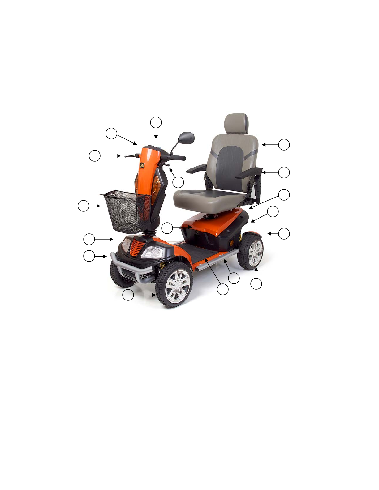
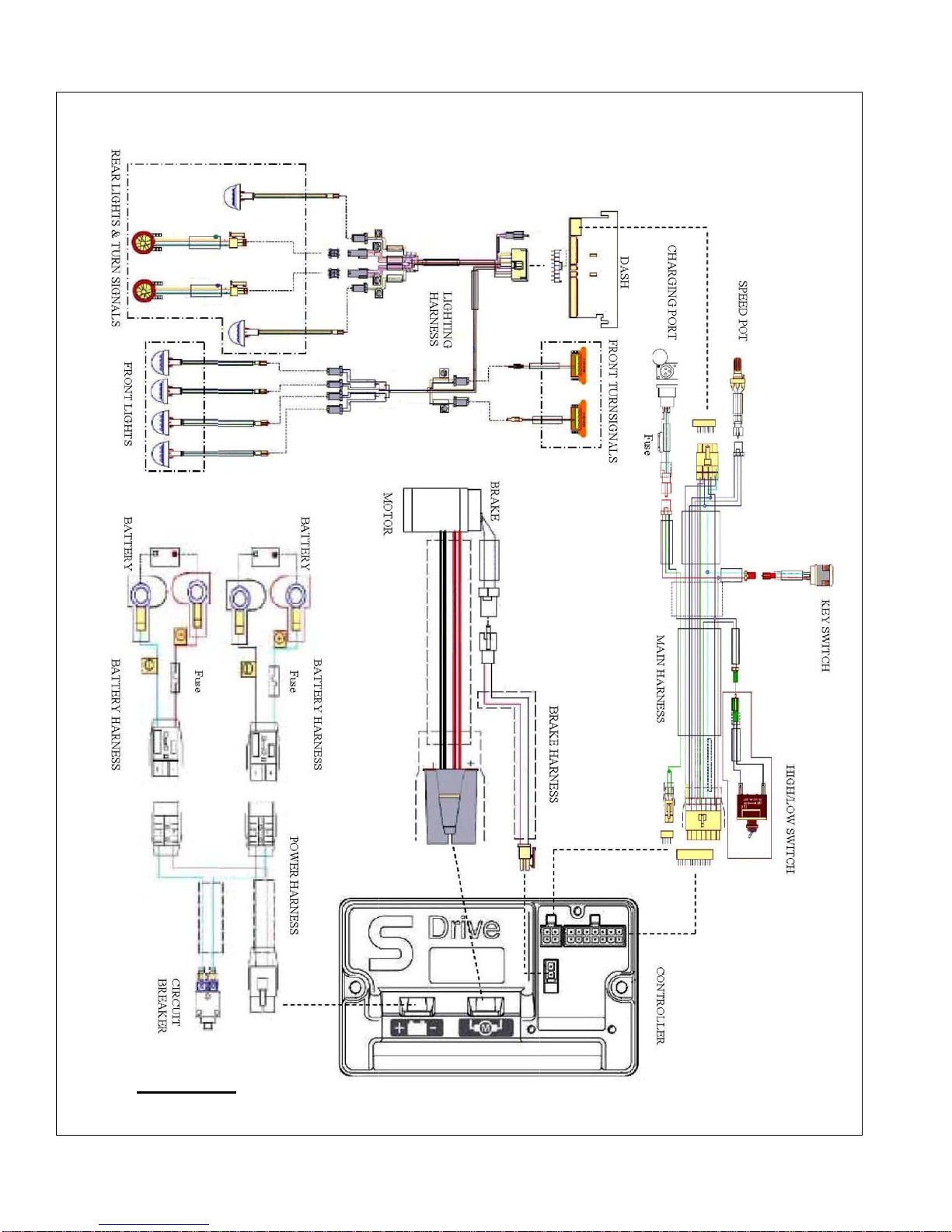
Component: Circuit Breaker
Location: Mounted on the front of the battery compartment.
Function: Protects battery circuit from current overload. When the current draw exceeds breaker rating, the
circuit breaker will open.
Connections: Two terminals on the circuit breaker connect the circuit breaker to the batteries.
Failure Signs: Opens repeatedly. May indicate a failed circuit breaker or short in the wiring. Also, may open if
the motors are overloaded (from excessive weight, excessive uphill driving, etc).
Test: Measure resistance across circuit breaker. Check for continuity across wires between circuit breaker and
batteries.
Expected reading: Less than 10 ohms.
Serviceable: Circuit breaker must be replaced with exact current rating. Replace wires as necessary.
Component: Battery Charger (Model: HP1202B, off-board charger only).
Location: Off-Board
Function: Recharges batteries. There is one LED on the charger. The LED is red when the charger is plugged
into an electrical outlet. If the LED does not go on, then check the electrical outlet. When the charger is on and
plugged into the charger port, an orange LED indicates that the batteries are charging. A green LED indicates
that the batteries are fully charged.
Connections: Charging Port and AC wall outlet.
Failure Signs: LED does not go on. Batteries will not charge.
Tests: Test for voltage. Test by measuring DC output of the charger.
Expected reading: 24.5VDC - 27VDC
Serviceable: Replace if necessary.
Component: Charging Harness
Location: Inside the rear tiller shroud.
Function: Provides external charger with connection to the batteries.
Connections: Charger port
Failure Signs: Batteries will not charge.
Tests: Test for voltage across the two outside pins of the charging port. Test harness for continuity.
Expected readings: Total battery voltage.
Serviceable: Replace as necessary.
Component: Power Harness
Location: Mounted inside the battery compartment.
Connections: Batteries, Circuit Breaker, and Controller
Function: Provides voltage to the controller.
Failure Signs: Scooter will not run.
Tests: Test for continuity.
Expected readings: Not open.
Serviceable: Replace as necessary.

Patriot_SG_REVA_050714
6
Component: Motor
Location: Rear section of scooter on transaxle.
Function: Drives the scooter.
Connections: Controller
Failure Signs: Scooter runs slowly or not at all.
Tests: Test for internal resistance in motor. Test motor wires for continuity. See Beep Code #8.
Expected readings: Internal resistance is less than 50 ohms but not shorted. (Note: Can be as low as 0.2 ohms).
Serviceable: Replace motor brake.
Component: Motor Brake
Location: End of motor.
Function: Parking brake for the motor.
Connections: Controller
Failure Signs: Scooter will not move or moves sluggishly. No audible click when the scooter stops.
Tests: Test for open. See Beep Code #5.
Expected readings: Less than 80 ohms but not shorted.
Serviceable: Replace motor brake.
Component: Controller
Location: Mounted inside the battery compartment.
Function: Monitors the system and beeps when something in the system is out of range. These faults are heard
as a fast series of Beeps, followed by a Beep Code (BEEP CODES 2, 3, and 5-9).
Connections: Batteries, Motor, Motor Brake, Charging Port, and Main Harness.
Failure Signs: Beep Code #9.
Tests: Test for voltage to motor when paddle is pressed.
Expected readings: Voltage varies.
Serviceable: Replace as necessary.
Component: Main Harness
Location: Front and rear sections of the scooter.
Function: Connects controller to the dashboard.
Connections: Dashboard, Hand Brake, Key Switch, Charging Port, High/Low Switch, and Controller.
Failure Signs: Scooter does not run or runs slowly.
Tests: Test for voltage at (batteries and key switch), resistance at (speed pot and throttle pot), and continuity.
Expected readings: 24VDC (batteries and key switch), resistance (speed and throttle pot) varies, and continuity
not open.
Serviceable: Replace as necessary.
Component: Paddle Assembly (throttle Pot)
Location: Underside of the dash.
Function: The throttle pot uses variable resistance to control speed and direction of travel by reversing polarity.
Connections: Dashboard
Failure Signs: Beep Codes #6 and #7
Tests: Test resistance with the paddle deflected either way.
Expected readings: Depends on direction of deflection.
Serviceable: Replace dash.

Patriot_SG_REVA_050714
7
Component: Speed Pot
Location: Dash
Function: The speed potentiometer (pot) uses variable resistance to control the top speed of the scooter.
Connections: Dashboard and Main Harness
Failure Signs: Speed will not vary when knob is turned.
Tests: See Beep Code #7
Expected readings: Depends on speed pot position.
Serviceable: Replace the dash.
Component: Dash
Location: Mounted on top of the tiller
Function: Provides connectivity between controller and key switch, battery meter, throttle pot, and speed pot.
Connections: Main Harness, Lighting Harness(es), and Throttle Pot.
Failure Signs: Damaged or loose connectors. Pins not seated properly in connectors.
Serviceable: Replace as necessary.
Component: High/Low Switch
Location: Mounted on the rear tiller
Function: Provides connectivity to the controller.
Connections: Main Harness
Failure Signs: Scooter speed does not increase/decrease when the switch is operated.
Serviceable: Replace as necessary.

Patriot_SG_REVA_050714
8
TYPICAL S-DRIVE WIRING DIAGRAM
S-DRIVE TILLER INTERFACE SOCKET DETAILS
PIN NUMBER DESCRIPTION WIRE COLOR
1 Throttle Wiper Yellow
2 Throttle High Reference Orange
3 Audible Alarm Purple
4 Slow/Fast Switch Yellow
5 On/Off Switch White
6 Inhibit 2 N/A
7 24V Red
8 Throttle Low Reference Blue
9 Speed Limiting Potentiometer Gray
10 Status Indicator Green
11 Spare N/A
12 Reverse Switch N/A
13 0V Black
14 Inhibit 3 N/A

Patriot_SG_REVA_050714
9
PATRIOT
WIRING DIAGRAM

Patriot_SG_REVA_050714
10
Scenario 1: Turn the Key to the On Position and No Power
Put the key into the key switch and turn to the on position. There is no power to the control panel. The horn
does not work, the lights do not work, and the battery condition meter does not work. Battery voltage travels
from the batteries, through the controller and the key switch. The test below will verify that there is battery
voltage at the batteries, the controller, the main harness, and the key switch.
Check Battery Voltage
1) Remove the seat.
2) Remove the battery cover.
3) Measure voltage across the terminal with the red wire on one battery and the terminal with the black wire on
the other battery.
• 24VDC (or battery voltage?) - Go to the next step.
• More than 16VDC? - Try to recharge the batteries. Load test and replace if necessary.
• 0VDC? - Check the battery fuse for continuity. Replace with 125A fuse if necessary. Check main circuit
breaker (1) and main power harnesses for continuity (6a to 6b/6c and 7a to 7b/7c.) Replace as necessary.
Check Voltage at Controller
4) Unplug the power harness from the controller. This connection is marked with the symbol. Measure
the voltage across the red and black wires.
• 24VDC (or battery voltage?) - Go to the next step.
• 0VDC? - Check circuit breaker and wire harnesses for continuity. Replace as necessary.
Check Voltage out of Controller
5) Make sure that the power harness is plugged back into the controller.
6) Insert the multimeter probes into the terminal with the red wire (pin 7) and the terminal with the black wires
(pin 13) on the back of the main harness. Refer to the “Interface Socket Details” on page 8 and/or the wiring
diagram on page 27.
• 24VDC (or battery voltage?) - Go to the next step.
• 0VDC? - Replace the controller.
Check Voltage at Main Harness
7) Place the multimeter probes into pin 1 and pin 2 (outside pins) of the charging port.
8) Measure voltage.
• 24VDC (or battery voltage?) - Go to the next step.
• 0VDC? - Replace the main harness.
Check Key Switch
9) Remove the front basket bracket.
10) Remove the front tiller shroud.
11) Open the control panel fuse holder. Check the fuse for continuity.
• Open? - Replace the 3A fuse.
• Less than 10 ohms? - go to the next step.
12) Disconnect the key switch connector from the main harness. Make sure that the key is in the on position.
Measure continuity across the two pins on the key switch connector.
• Continuity? - Replace the main wiring harness.
• Open? - Replace the key switch.

Patriot_SG_REVA_050714
11
Scenario 2: Batteries Will Not Charge
Most battery chargers need to "see" least 16VDC at the charger port. Otherwise, they may not send a charging
current to the batteries. This test will ensure that the battery voltage is making it to the charger port. You will
need to check battery voltage at the batteries, at the controller, out of the controller, and at the charger port.
Check Battery Charger Voltage
1) Remove the seat.
2) Remove the battery cover.
3) Plug the charger into the charger port and then into a wall outlet.
4) Measure voltage across the terminal with the red wire on one battery and the terminal with the black wire on
the other battery. Does the voltage increase?
• Yes? - Load test the batteries and replace as necessary.
• No? - But there is voltage. If the voltage is lower than 16VDC, then replace the batteries. If the voltage is
16VDC or greater, then go to the next step.
• No? - And there is no voltage. Check the circuit breaker, power wire harness, battery harnesses and their
fuses for continuity. Replace the individual components as necessary.
Check Voltage Into the Controller
5) Measure voltage across the B+ (red wire) and B- (black wire) of the power harness. This is the large black
connector on the controller marked with the symbol.
• 24VDC (or battery voltage?) - Go to the next step.
• 0VDC? - Check circuit breaker and wire harnesses for continuity. Replace as necessary.
Check Voltage Out of the Controller
6) Insert the multimeter probes into the terminal with the red wire (pin 7) and the terminal with the black wire
(pin 13) on the back of the main harness (14-pin) connector. Refer to the wiring diagram on page 27.
• 24VDC (or battery voltage?) - Go to the next step.
• 0VDC? - Replace the controller.
Check Voltage at the Main Harness
7) Remove the front basket bracket.
8) Remove the front tiller shroud.
9) Disconnect the charger harness (red 3-pin connector with a red, green, and black wire) from the main harness.
10) Measure voltage across the two outside terminals, a black wire and a red wire on the main harness connector.
Refer to the wiring diagram on page 27.
• 24VDC (or battery voltage?) - Go to the next step.
• 0VDC? - Replace the main harness.
11) Check the charger harness fuse for continuity.
• Continuity? - Replace the charger harness.
• Open? - Replace the 15A fuse.

Patriot_SG_REVA_050714
12
BEEP CODES
The S-Drive controller uses audible beeps to indicate the status of the system. When the controller notices that
there is a malfunction in the system, it will beep a code when the power is on. The signal will be a set of fast
beeps lasting two seconds. The slower diagnostic pattern will then be sounded once. For example, when it
Beeps five times and stops, that indicates BEEP code #5 – Brake Trip.
The following BEEP codes are used to help diagnose system errors:
BEEP Code #2 – Low Battery Voltage
BEEP Code #3 – High Battery Voltage
BEEP Code #5 – Solenoid Brake Trip
BEEP Code #6 – Throttle Trip (Out of Neutral)
BEEP Code #7 – Throttle Trip/Speed Control Fault (Voltage Error)
BEEP Code #8 – Motor Disconnected
BEEP Code #9 – Possible Controller Trip
BEEP CODE #2 – LOW BATTERY VOLTAGE
The batteries need charging or there is a bad connection to the batteries. Check the connections to the batteries.
If the connections are good, try charging the batteries. If the batteries will not charge, load test them or refer to
“Scenario 2: Batteries will not Charge.”
BEEP CODE #3 - HIGH BATTERY VOLTAGE
An excessive voltage has been applied to the S-drive. This is usually caused by a poor battery connection.
Check the battery connections. NOTE: The error may only be present when going down hill and power goes
back to the batteries.
1) Insert the key into the key switch and turn it to the on position. Allow the battery level to drop. Do not allow
the battery voltage to fall into the red area on the battery meter.
2) Check the battery charger. Make sure it is an approved charger.
BEEP CODE #5 – SOLENOID BRAKE TRIP
The parking brake has a bad connection. Check the parking brake and motor connections. Make sure all the
system connections are secure.
1) Turn the key to the off position.
2) Disengage and then re-engage the park brake.
3) Turn the key to the on position. Did the flash code clear?
• Yes? - OK.
• No? - Go to the next step.
4) Remove the seat and the battery cover.
5) Disconnect the brake harness (2-pin connector) from the controller.
6) Make sure that the pins are seated properly. Measure resistance across pin 1 (red wire) and pin 2 (black wire)
of the brake harness with the park brake engaged.
• 80 ohms or less but not shorted? – Replace the controller.
• Shorted or open? – Go to the next step.
7) Disconnect the brake harness from the brake.
8) Make sure that the pins are seated properly. Make sure the contacts are not corroded or discolored. Check the
continuity between pin 1 and pin 2 of the brake with the park brake engaged.
• 80 ohms or less but not shorted? – Replace the brake harness.
• Corroded or discolored? – Replace as necessary.

Patriot_SG_REVA_050714
13
• Shorted or open? – Replace the motor/brake assembly.
BEEP CODE #6 – THROTTLE TRIP (OUT OF NEUTRAL)
A throttle trip is indicated. Make sure the paddle is in the neutral position before switching on the scooter.
1) Turn the key to the off position.
2) Make sure that the paddle pot is not obstructed and it can return to the neutral (center) position.
3) Move the paddle forward and then reverse. Make sure that it is not obstructed. Does it spring back to neutral
position?
• Yes? – Go to the next step.
• No? – Check for obstructions. Replace the dash assembly.
4) Turn the key to the on position. Does the code return?
• No? – OK
• Yes? – Go to FLASH CODE #7 to test the throttle pot.
BEEP CODE #7 – THROTTLE TRIP/SPEED CONTROL FAULT (VOLTAGE ERROR).
A throttle trip is indicated. Indicates a problem with the throttle control or speed control.
1) Remove the seat.
2) Remove the battery cover.
3) Turn the speed pot to full rabbit.
4) Set your multimeter to measure resistance.
5) Disconnect the main harness from the controller.
7) Insert the multimeter probes into the main harness connector at pin 1 (yellow wire) and pin 8 (blue wire).
Note the resistance reading. Insert the multimeter probe into the main harness connector at pin 1 (yellow wire)
and pin 2 (orange wire). Note the resistance reading. Readings should be 2.5k ohm ±10%.
• Are both readings within 250 ohms? - Replace the controller.
• Either of the readings outside that range? - Go to the next step.
8) Remove the front basket bracket.
9) Remove the 10 screws that fasten the front tiller shroud to the rear tiller shroud.
10) Remove the 2 screws connecting the dashboard to the front tiller shroud.
11) Disconnect the (P1) connector from the dashboard.
12) Measure the resistance from the center pin (P0) of the throttle pot to either of the outside pins. Note the
resistance reading. Measure the resistance from the center pin (P0) of the throttle pot to the opposite outside pin.
Note the resistance reading. Readings should be 2.5k ohm ±10%.
• 2.5k ohm ±10%? - Note the resistance reading and go to the next step.
• Outside that range? - Replace the dash assembly.
13) Check the orange, blue, and yellow wires on the main harness for continuity. On the controller side, pin 1
(yellow),
pin 2 (orange), and pin 8 (blue). On the dashboard connector (P1), pin 1 (yellow), pin 2 (orange), and pin 3
(blue). Refer to the wiring diagram on page 27.
• 10 ohms or less on each one? - Replace the speed pot.
• Open on any wire? - Replace the main harness.

Patriot_SG_REVA_050714
14
BEEP CODE #8 - MOTOR DISCONNECTED
Check the position of the freewheel switch. (Key must be turned off and back on to clear the fault code). The
motor has a bad connection. Check all the connections and leads between the motor and the S-drive.
1) Remove the seat.
2) Remove the battery cover.
3) Disconnect the motor harness from the controller. This is the large gray connector marked with the
symbol.
4) Make sure that the pins are seated properly on the motor harness.
4) Measure resistance across the motor + (thick red wire) and the motor – (thick black wire) on the motor harness.
• 50 ohms but not shorted? (NOTE: Can be as low as 0.2 ohms.) – replace the controller.
• Out of that range? – Go to the next step.
19) Remove the four brushes from the motor and inspect them. See figure 10 on page 17. Indications of a bad
brush include broken springs, cracked carbon, black or discolored wire, and black or discolored contacts.
• Worn or physically damaged? – Replace the brushes.
• Not worn or physically damaged? - Replace the motor/brake assembly.
BEEP CODE #9 – POSSIBLE CONTROLLER TRIP
A control system trip is indicated. Make sure all connections are secure.
1) Make sure that all connections are secure.
• If the code continues, then shut down the scooter and allow the controller to cool down.
• If the problem still persists, then replace the controller.

Patriot_SG_REVA_050714
15
Component Replacement Instructions
CONTROLLER REPLACEMENT
To replace the controller:
1) Place the freewheel lever in the engaged position.
2) Remove the key from the key switch.
2) Remove the seat.
3) Remove the four screws fastening the battery cover.
4) Unplug the connectors from the controller. Note the location of any wire ties used to secure the harnesses.
5) Remove the two screws that attach the controller to the controller bracket.
6) Remove the controller.
7) Install the new controller using the two screws removed in step 6.
8) Reconnect the harness connectors. See figure 3.
9) Reinstall the battery cover.
10) Reinstall the seat.
11) Insert the key into the key switch and operate the scooter.
Figure 2. Controller Location
Figure 3. Controller Connections
BAT+
BAT-
MOTOR BRAKE
MAIN HARNESS
CHARGER INHIBIT
MOTOR -
MOTOR+
CONTROLLER
CONTROLLER MOUNTING
BRACKET
SCREWS (QTY. 2)

Patriot_SG_REVA_050714
16
DRIVE WHEEL REPLACEMENT
To replace the drive wheel:
1) Place the freewheel lever in the engaged position.
2) Remove the key from the key switch.
3) Place a support under the scooter frame to raise the drive wheel.
4) Remove the center cap.
5) Remove the 19mm nut and washer that fastens the drive wheel to the axle. See figure 4.
6) Remove the drive wheel from the axle. Retain the axle key.
7) Place a new wheel onto the axle. Make sure the axle key is installed properly.
8) Reinstall the nut and washer and tighten securely.
8) Reinstall the center cap.
Figure 4. Drive Wheel
DASH REPLACEMENT
To replace the dash:
1) Place the freewheel lever in the engaged position.
2) Remove the key from the key switch.
3) Remove the (10) Phillips screws in the rear tiller cover. See figure 5.
4) Remove the (2) Phillips screws securing the basket bracket to the front tiller cover. See figure 6.
5) Remove the front tiller cover and the dash assembly by lifting them up.
6) Unplug the (4) cables from the dash and the (2) cables from the turn signals.
7) Remove the (2) Phillips screws on the underside of the dash, which secure the dash assembly to the tiller. See
figure 7 on page 17.
8) Assembly in the reverse order.
Figure 5. Rear Tiller Cover Figure 6. Basket Bracket
AXLE KEY (not shown)
DRIVE WHEEL
NUT
WASHER
CAP SPACER
19mm

Patriot_SG_REVA_050714
17
KEY SWITCH & HIGH/LOW SWITCH REPLACEMENT
To replace either switch:
1) Perform steps 1-7 of the dash replacement instructions on page 16.
2) Remove the (6) Phillips screws at the backside of the front tiller cover to access the switches. See figure 8.
3) Replace the switch(es) and assemble in reverse order.
4) Install the (6) Phillips screws removed in step 2 to secure the front tiller cover.
5) Perform steps 1-7 of the dash replacement instructions above in reverse order to complete the installation.
Figure 7. Inside Dash Figure 8. Inside Tiller (front section)
MOTOR BRUSH REPLACEMENT
To replace the motor brushes:
1) Remove the rear shroud. See figure 11 on page 18.
2) Remove a brush cap with a slotted screw driver.
2) Remove brush by gently prying it out of the holder.
3) Inspect the brush for discoloration, carbon build up, rust, uneven or excessive wear.
4) If defective, replace brush.
5) Repeat steps 2-4 for all four brushes. See figures 9 and 10.
Figure 9. Motor Brush Caps Figure 10. Brushes (shown removed)
Screws
Screws
CRACKED CARBON
BAD GOOD
DISCOLORED WIRES
WORN
SPRINGS

Patriot_SG_REVA_050714
18
MOTOR/BRAKE REPLACEMENT
To replace the motor/brake assembly:
1) Place the freewheel lever in the engaged position.
2) Remove the key from the key switch.
3) Remove the seat.
4) Remove the battery cover. (Optional: removal of the batteries will reduce the weight.)
5) Disconnect the motor and brake connections at the controller.
6) Remove the (4) Phillips screws that fasten the rear shroud and remove the shroud. See figure 11.
7) Cut the tie wrap(s) securing the motor/brake cable. See figure 12.
8) Remove the (2) 5mm Allen bolts (top and bottom bolts only) from the transaxle. See figure 12.
9) Slide the motor off the transaxle. Retain the motor coupler.
10) Install the motor coupler onto the shaft of the new motor/brake assembly.
12) Assemble in the reverse order.
Figure 11. Rear Shroud Figure 12. Motor/Brake Assembly
TRANSAXLE REPLACEMENT
To replace the transaxle:
1) Perform steps 1-7 of the motor/brake replacement instructions.
2) Place a support under the scooter frame forward of the u-brackets to raise the drive wheels off the ground to
allow removal of the transaxle. See figure 11.
3) Remove the center cap.
4) Remove the nut and washer that fastens the drive wheel to the axle. See figure 4 on page 16.
5) Remove the left-side drive wheel from the axle. Retain the axle key.
6) Remove the right-side drive wheel.
7) Slide the drum off the transaxle. See figures 13 and 14 on page 19.
8) Remove the hand brake cable.
9) Remove the hand brake assembly. Retain the axle key.
10) Remove the (2) 8mm bolts connect each u-bracket. Repeat on the opposite side. See figure 14 on page 19.
11) Remove the transaxle from the rear frame.
12) Assemble in the reverse order.
Screws
Bolts
(5mm)
Moto
r
Motor/Brake Cable

Patriot_SG_REVA_050714
19
Figure 13. Drum Brake (Rear Section)
Figure 14. Scooter (Rear Section)
Transaxle
Hand Bra
k
e
Drum
Drum
Hand Brake Assembly
Hand Brake Cable
Place support here.
Bolts
(
8mm
)
U - Bracket
Transaxle
Axle Key
Axle Key
Axle Key
Other manuals for PATRIOT GR575
1
Table of contents
Other Golden Mobility Aid manuals