manuals.online logo
Brands
  1. Home
  2. •
  3. Brands
  4. •
  5. golmar
  6. •
  7. Intercom System
  8. •
  9. golmar PE4-91C User manual

golmar PE4-91C User manual

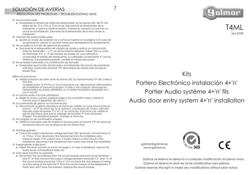
PORTERO ELECTRÓNICO
CHALET
CHALET AUDIO DOOR
ENTRY SYSTEMS
La comunicación por sistema
STOP
Golmar se reserva el derecho a cualquier modificación sin previo aviso.
Golmar reserves the right to make any modifications without prior notice.
PE4-91C
PES4-91C
T93
rev. 0100
ESQUEMA INSTALACIÓN: Dos puertas de acceso con dos pulsadores.
INSTALLATION DIAGRAM: Two access doors with two push buttons.
CV CV
A-490C/1
NR
+
-
2
0 230
PRI 1
A-490C/2
1
Vout Vin
L1 L2 CV CV A
2
+
--
PE4-91C
12 3
SW
4
STOP
1
Vout Vin
L1 L2 CV CV A
2
+
--
PE4-91C
12 3
SW
4
STOP
SA HZ
+
-
T-840
1
12345678 910
SA HZ
+
-
T-840
1
12345678 910
SECCIONES MINIMAS. / MINIMUM SECTIONS.
0.5mm
+~1~2
1.0mm
1.0mm2.5mm
100m.200m.300m.
2.5mm
2
22
2
2
-
0.75mm
2
1. Normas de instalación.
1.1 No apretar excesivamente los tornillos de la regleta de los alimentadores.
1.2 Conectar siempre los alimentadores a través de un magnetotérmico o de un enchufe macho.
1.3 Cuando se instale el equipo, hacerlo sin alimentación. Desconectar la alimentación para cualquier
modificación en la instalación.
1.4 No coloque los teléfonos hasta verificar la instalación.
2. Comprobación de la instalación.
2.1 Conectar el alimentador A-490C/1 a la red. Verificar que la tensión de entrada al alimentador no supera
los 230Vc.a.
2.2 Comprobar que las tensiones del alimentador son las indicadas en las instrucciones adjuntas con el
alimentador; si no es así, desconecte el alimentador de la instalación y vuelva a medir las tensiones. Si
ahora son correctas, hay un cruce en la instalación. Desconecte el alimentador y revise la instalación.
2.3 El indicador de canal ocupado “Stop” debe estar apagado; si no es así, la instalación no es correcta.
Revise la instalación y, ante cualquier duda, llame a su distribuidor.
2.4 Codificar los teléfonos en función del código correspondiente al pulsador que debe realizar la llamada a
cada vivienda, según se indica en las instrucciones adjuntas al teléfono.
2.5 Instalar ahora los teléfonos, y comprobar que cada pulsador llama a la vivienda que le corresponde; si no
es así, revisar la codificación de los teléfonos.
1. Installation rules.
1.1 Do not use excessive force when tightening the connector screws on the transformer.
1.2 Always connect the transformers using a magnetothermic or a male plug.
1.3 Install the equipment without the power connected. Disconnect from power for any modification to the
system.
1.4 Do not connect the telephones until the installation has been checked.
2. Checking the installation.
2.1 Connect the A-490C/1 transformer to the mains. Check that the input voltage is lower than 230Va.c.
2.2 Check that the output voltages are as shown on the power supply instructions; if not, disconnect the
transformer from the installation and measure again. If they are correct now, it means there is a short
circuit in the installation. Disconnect the transformer and check the installation.
2.3 The “Stop” busy channel indicator should be off; if not, the installation is wrong. Check the installation and,
if any doubt, contact your distributor.
2.4 Code the telephones according to the code corresponding to its push button on the door panel, as shown
on the telephone instruction manual.
2.5 Install the telephones now and check that each push button calls to the corresponding flat; if not, check the
telephone coding.
IMPORTANTE.
IMPORTANT.
ESQUEMA INSTALACIÓN: Una puerta de acceso con dos pulsadores.
INSTALLATION DIAGRAM: One access door with two push buttons.
1
Vout Vin
L1 L2 CV CV A
2
+
--
CV
A-490C/1
NR
+
-
2
0 230
PRI 1
A-490C/2
SA HZ
+
-
T-840
1
12345678910
SA HZ
+
-
T-840
1
12345678910
SECCIONES MINIMAS. / MINIMUM SECTIONS.
0.5mm
+~1~2
1.0mm
1.0mm 2.5mm
100m. 200m. 300m.
2.5mm
2
22
2
2
-
0.75mm
2
12 3
SW
4
PE4-91C
STOP
DESCRIPCIÓN DE LAS PLACAS.
DOOR PANELS DESCRIPTION.
i
j
L2 ACV CVIN
V
-L1
V
OUT+
21 -
ARRIBA UP
P1CV~
k
n
i
o
p
q
r
s
t
m
l
255
a
b
c
h
cf
128
e
d
STOP
g
Módulo informativo. / .Informative modulea
Pulsador de luz. / .Light push button
Indicador de canal ocupado. / .Busy channel indicator
Pulsador(es) de llamada. / .Call push button(s)
Orificio micrófono. / .Microphone hole
Rejilla protectora altavoz. / .Protective speaker grille
Marcos laterales. / .Side frames
Cabezales embellecedores. / .Decorative head frames
Orificios sujeción placa. / Panel fixing holes.
b
c
d
e
f
g
h
i
Pulsadores. / Push buttons.
Junta de estanqueidad. / Waterproof seal.
Módulo de sonido. / Sound module.
Ajuste de volúmenes de audio. / Audio volume adjustments.
Puentes configuración placa. / Door panel configuration jumpers.
Circuito C.V.O. / C.V.O. circuit.
Lengüeta sujeción lámpara. / Lamp placing tab.
Orificios sujeción circuito C.V.O. / C.V.O. circuit fixing holes.
Regleta conexión C.V.O. / C.V.O. terminal connector.
l
m
n
o
p
q
r
s
t
Soporte módulo informativo. / Informative module holder.
j
Regleta de conexión PLUZ-91. / PLUZ-91 terminal connector.
k
~1 L1ICO +VO M-+V
ESQUEMA INSTALACIÓN: Una puerta de acceso con un pulsador.
INSTALLATION DIAGRAM: One access door with one push button.
1
Vout Vin
L1 L2 CV CV A
2
+
--
PES4-91C
12 3
SW
4
CV
A-490C/1
NR
+
-
2
0 230
PRI 1
A-490C/2 STOP
SECCIONES MINIMAS. / MINIMUM SECTIONS.
0.5mm
+~1~2
1.0mm
1.0mm 2.5mm
100m. 200m. 300m.
2.5mm
2
22
2
2
-
0.75mm
2
SA HZ
+
-
T-840
1
1234567 8910
INSTALACIÓN DE LA PLACA.
DOOR PANEL INSTALLATION.
1Colocar las etiquetas identificativas en los pulsadores. 2Empotrar, enrasar y nivelar la caja de empotrar.
Level and flush fit the box.Place the identifying labels in the push buttons.
6Cerrar la placa y colocar los marcos embellecedores.
Close the door panel and use the decorative frames.
5Verifique y ajuste el sistema.
Check and adjust the system.
Pulsador doble
Double push button
Comprobar que el equipo funciona correctamente.
En caso de ser necesario, ajustar mediante un destornillador el
volumen de audio.
Check that the system is working properly.
If necessary, adjust the audio level by using an screw driver.
Pulsador individual
Single push button
1650
1850
1450
3Fijar el circuito CVO en la caja y configurar los puentes.
Fix the CVO circuit in the flush fitting box and set the jumpers.
1
2
3
4
. Cuando haya más de una placa, quitarlo en todas, excepto
en la placa más próxima a los teléfonos.
. No quitar nunca. /
.
When there is more than one door panel, remove in all,
except at the closest panel to the telephones.
Never remove.
No quitar nunca. /
. No quitar nunca. /
Never remove.
Never remove.
ARRIBA UP
116 1 20
123 4
V
IN
-21 +V
OUT
-CVL2L1 CV A
AJUSTE VOLUMENES.
AUDIO LEVEL ADJUSTMENTS.
4Sujetar la placa a la caja de empotrar con los muelles bisagra.
Fix the panel in the flush fitting box using the springed hinge.
Conectar el circuito CVO a la placayalainstalación.
Connect the CVO circuit to the door panel and to the installation.
1. Recepción de llamadas procedentes de la placa.
Para realizar la llamada el visitante deberá presionar el pulsador de la placa correspondiente a la
vivienda con la que desea establecer comunicación. Durante la pulsación, un tono acústico confirmará que la
llamada se está realizando. Si se ha presionado por equivocación el pulsador de la otra vivienda, pulsar
sobre el que corresponda con la vivienda deseada; esto anulará la primera llamada.
Caso de existir más placas, éstas quedarán desconectadas, visualizándose mediante el indicador “Stop”.
En este instante el teléfono recibe la llamada, que tendrá una duración de 5 segundos. Si transcurridos
30 segundos no se ha descolgado el auricular del teléfono, teléfono y placas pasarán al estado de reposo.
Para establecer comunicación descolgar el auricular del teléfono: en dicho instante se iluminará el
indicador “Stop” de la placa activa. La comunicación tendrá una duración máxima de un minuto y medio, o
hasta colgar el auricular. En dicho instante la(s) placa(s) pasará(n) al estado de reposo inicial.
Para accionar el abrepuertas, pulsar el botón naranja durante los procesos de llamada o comunicación;
con una sola pulsación se acciona el abrepuertas durante unos 4 segundos aproximadamente.
2. Llamada desde la puerta del rellano.
Este teléfono permite la sustitución del timbre convencional de puerta. Al recibir la llamada desde el
pulsador de puerta, el teléfono emite un tono continuo, distinto al de la llamada desde la placa.
FUNCIONAMIENTO.
OPERATION.
1. Calling from the door panel.
To make a call, the visitor should press the button corresponding to the apartment he wishes to contact.
An acoustic tone will be heard confirming the call as the button is pushed. During the call the visitor can correct
his call by pressing a button corresponding to a different apartment, in wich case the original call is cancelled.
In case of several door panels, they will be disconnected, shown by the “Stop” busy channel indicator.
At this moment the call sound will be received at the telephone in the dwelling, lasting in 5 seconds. If the
call is not answered after 30 seconds, the channel will be freed.
To stablish communication, pick up the telephone handset: at that moment the indicator light “Stop” at
the active door panel will light. Communication lasts for one and a half minutes or until the handset is
replaced. The “Stop” light at the panel(s) goes out, and the channel is freed.
To open the door, press the door release button during call or communication progresses; with one
press, the door release operates for approximately 4 seconds.
2. Call reception from the flat door bell push button.
This telephone allows the replacement of the door bell. When a call is received from the door push
button, an acoustic tone will be heard on the telephone, different that the produced when the call is done from
the door panel.
This manual suits for next models

1

Other golmar Intercom System manuals

golmar G2+ Soul S5110 Art 4 User manual

golmar

golmar G2+ Soul S5110 Art 4 User manual

golmar SHINER-90 User manual

golmar

golmar SHINER-90 User manual

golmar Stadio Plus T4000ML User manual

golmar

golmar Stadio Plus T4000ML User manual

golmar 50124319 User manual

golmar

golmar 50124319 User manual

golmar Kit SOUL S5110/ART 4 LITE User manual

golmar

golmar Kit SOUL S5110/ART 4 LITE User manual

golmar T500ML User manual

golmar

golmar T500ML User manual

golmar T631/PLUS User manual

golmar

golmar T631/PLUS User manual

golmar Stadio Plus User manual

golmar

golmar Stadio Plus User manual

golmar TKIT632 User manual

golmar

golmar TKIT632 User manual

golmar T22ML Surf User manual

golmar

golmar T22ML Surf User manual

golmar 7W/G2+ User manual

golmar

golmar 7W/G2+ User manual

golmar Rock Series User manual

golmar

golmar Rock Series User manual

golmar GB2 Vesta 2 User manual

golmar

golmar GB2 Vesta 2 User manual

golmar Gtwin Series User guide

golmar

golmar Gtwin Series User guide

golmar G2+ Art 4 User manual

golmar

golmar G2+ Art 4 User manual

golmar SV-372S Colour User manual

golmar

golmar SV-372S Colour User manual

golmar T-540 Uno User manual

golmar

golmar T-540 Uno User manual

golmar Stadio Plus 4113/AL User manual

golmar

golmar Stadio Plus 4113/AL User manual

golmar EL620/2Plus User manual

golmar

golmar EL620/2Plus User manual

golmar TEKNA-S GTWIN User manual

golmar

golmar TEKNA-S GTWIN User manual

golmar G2+ User manual

golmar

golmar G2+ User manual

golmar Jazz GB2 User manual

golmar

golmar Jazz GB2 User manual

golmar TSzena ML User manual

golmar

golmar TSzena ML User manual

golmar NHEA PLUS SE TERMINAL User manual

golmar

golmar NHEA PLUS SE TERMINAL User manual

Popular Intercom System manuals by other brands

HIK VISION DS-KD8003-IME1 quick start guide

HIK VISION

HIK VISION DS-KD8003-IME1 quick start guide

Audio Tech 560W-A operating instructions

Audio Tech

Audio Tech 560W-A operating instructions

Clear-Com FreeSpeak II user guide

Clear-Com

Clear-Com FreeSpeak II user guide

HIK VISION DS-1350HM user manual

HIK VISION

HIK VISION DS-1350HM user manual

Sentryus NC-DS2 Operation and installation manual

Sentryus

Sentryus NC-DS2 Operation and installation manual

VIDEOTECH DX471 Firmware update

VIDEOTECH

VIDEOTECH DX471 Firmware update

HIK VISION DS-KH6320-WTE1-W installation guide

HIK VISION

HIK VISION DS-KH6320-WTE1-W installation guide

Aiphone RY-SP instructions

Aiphone

Aiphone RY-SP instructions

Silvercrest STK 16 B3 Assembly, operating and safety instructions

Silvercrest

Silvercrest STK 16 B3 Assembly, operating and safety instructions

HIK VISION DS-KH6100-E1 user manual

HIK VISION

HIK VISION DS-KH6100-E1 user manual

Channel Plus 6110 owner's manual

Channel Plus

Channel Plus 6110 owner's manual

Nywint DJ5A quick start guide

Nywint

Nywint DJ5A quick start guide

Telegärtner DoorLine Slim DECT Operating and assembly instructions

Telegärtner

Telegärtner DoorLine Slim DECT Operating and assembly instructions

DoorBird D10x Series installation manual

DoorBird

DoorBird D10x Series installation manual

ADATIS TouchEntry-XS manual

ADATIS

ADATIS TouchEntry-XS manual

Konig SEC-PH360 manual

Konig

Konig SEC-PH360 manual

Fasttel Wizard Classic manual

Fasttel

Fasttel Wizard Classic manual

BARIX Annuncicom 60 quick start guide

BARIX

BARIX Annuncicom 60 quick start guide

manuals.online logo
manuals.online logoBrands
  • About & Mission
  • Contact us
  • Privacy Policy
  • Terms and Conditions

Copyright 2025 Manuals.Online. All Rights Reserved.