manuals.online logo
Brands
  1. Home
  2. •
  3. Brands
  4. •
  5. golmar
  6. •
  7. Intercom System
  8. •
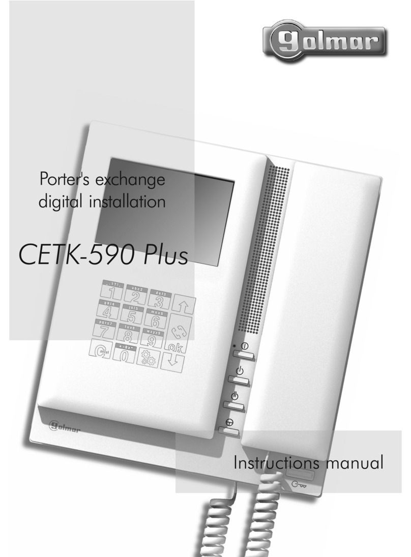
  9. golmar Soul kit User manual

golmar Soul kit User manual

TS ART5110 7W ML GR .0419REV
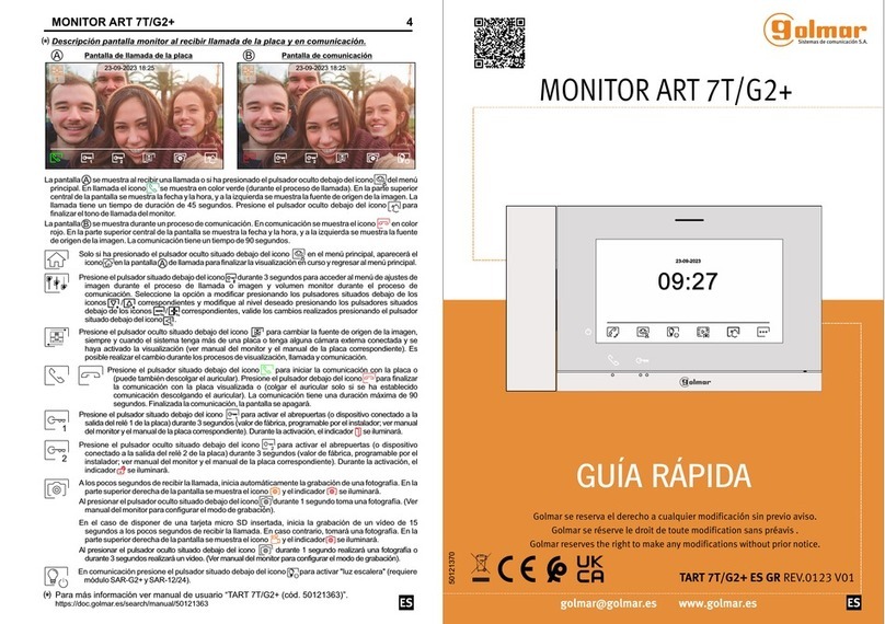
Guía rápida / / /Quick guide Guide rapide Guia rápidoSnel handleiding /
Kit Soul
12Vc.c. / 270mA12Vd.c. /
ABREPUERTAS / / /LOCK RELEASE GÂCHE ÉLÉCTRIQUE DEUROPENER TRINCO/
PULSADOR DE SALIDA / / /EXIT BUTTON BOUTON DE SORTIE DEUROPENERKNOP /
12Vc.a. / 12Va.c. /850mA.
Utilizar , y el varistor suministradoun relé y un transformador adecuados al consumo . El
ejemplo muestra un relé Golmar -12/24 y un transformador -104 (12Vc.a. / 1,5A).SAR TF
Use um relé e um transformador adequado para consumo, e o varistor fornecido. O exemplo
mostra um relé Golmar SAR-12/24 e um transformador TF-104 (12Vc.a./1.5A).
Use a correct power supply and relay to control the door opener, also apply the varistor. As an
example, a Golmar SAR-12/24 relay and power supply TF-104 (12Vac. / 1.5A) is used.
Gebruik een juiste voeding en relais om de deuropener te kunnen sturen pas ook de varistor
toe Als voorbeeld een
,
. Golmar SAR-12/24 TF-104 (12V c. / 1,5A).rela ais en
Utilisez un relais et un transformateur adaptés à la consommation et la varistance fournie.
L'exemple montre un relais Golmar -12/24 et un transformateur -104 (12Vc.a./1.5A).
,
SAR TF
CV-BUS CV+ AP+BUS
CV-BUS CV+ AP+BUSININCNC NA
PRIPRI
SECSEC
100~240V ac
S5110/ 7WART Art 7W Wi-Fi
8
CV-
GND
BUS
C
CV+
CCTV
AP+
AP-
BUS
NA
Golmar S.A. - Silici 13 - 08940 Cornellá de Llobregat - Spain
- www. golmar.es
Golmar se reserva el derecho a cualquier modificación sin previo aviso.
Golmar se réserve le droit de toute modification sans préavis.
Golmar reserves the right to make any modifications without prior notice.
golmar@golmar.es
50122096
/BOTÃO DE SAÍDA
Manual de instrucciones escanear el código QR.
Manuel d'instructions scannant le code .QR
Handleiding beschikbaar door de QR-code te scannen.
Manual de instruções digitalizando o código .QR
Instrucctions manual by scanning the code.QR
QR
Cód. 5012 1262
Abrepuertas
12Vc.a / 850mA
Abrepuertas
12Vc.c / 270mA
S5110/ 7WART 2S5110/ 7WART 3
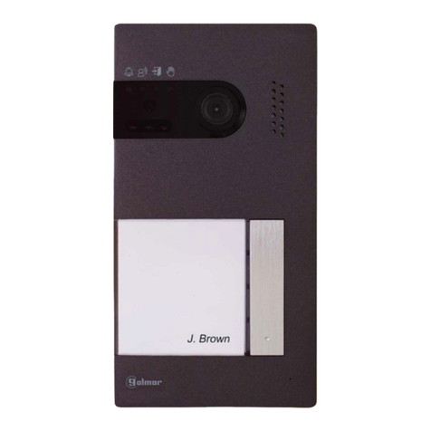
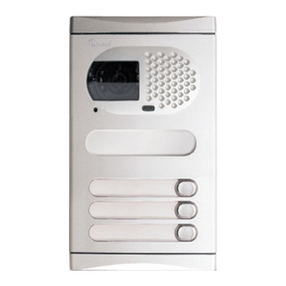
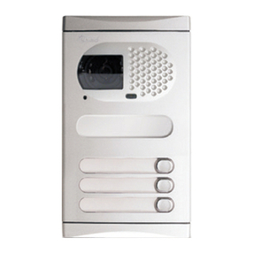
PLACA SOUL / /SOUL DOOR PANEL PLAQUE DE RUE SOUL /SOUL BUITENDEUPANEEL
Instalación
Installation
Antes de volver a colocar el lector y cerrar la placa, realice los ajustes indicados en el manual
de instrucciones (programación de llaves de proximidad, ajuste del nivel de audio, ...).
Asegúrese de que la junta de estanqueidad del lector de proximidad está bien colocada.
1. Ubique la parte superior de la plantilla a una altura de , y realice tres agujeros de 6mm
en los puntos indicados. Coloque los tacos suministrados.
1,65m
3. Quite los tornillos que sujetan el lector de proximidad y pase los cables de instalación a través de
la junta pasacables.
5. Conecte los cables a los terminales extraíbles siguiendo las indicaciones de los esquemas.
Evite exponer la placa a contraluces provocados por . Para una
correcta instalación, utilice la plantilla suministrada.
fuentes de luz (sol, farolas, ...)
4. Fije la placa a la pared mediante los tornillos suministrados.
2. Retire el frontal metálico de la placa aflojando el tornillo de la parte inferior con la llave que se
adjunta. En la parte posterior del frontal encontrará la etiqueta de personalización del pulsador.
4. Fix the door panel to the wall using the screws provided.
2. Remove the metal front of the door panel by loosening the screw on the bottom with the key
that is attached. On the back of the front you will find the name holder label.
Before replacing the proximity reader and closing the door panel, make the adjustments
indicated (programming of proximity keys, adjusting the audio
level, ...). Make sure that the sealing gasket of the proximity reader is correctly positioned.
on the installation manual
Avoid exposing the door panel to backlighting caused by light sources (sun, lampposts, ...). For
a correct installation, use the supplied template.
5. Connect the cables to the removable wiring connectors following the installation diagrams.
3. Remove the screws that hold the proximity reader and pass the installation cables through
the cable gland seal.
1. Locate the top of the template at a height of 1.65m, and make three 6mm holes at the
indicated points. Insert the supplied plugs.
Installation
Éviter les reflets générés par les éventuelles sources de lumière Pour
une installation correcte, utilisez le gabarit fourni.
(soleil, réverbères, ...).
3. Retirez les vis qui retiennent le lecteur de proximité et faites passer les câbles d'installation à
travers l'entrée pour câblage.
1. Localisez le haut du gabarit à une hauteur de 1,65 m et faites trois trous de 6 mm aux points
indiqués. Placez les fourni schevilles e .
2. à l'aide
de la clé fournie.
Retirez l’avant métallique en desserrant la vis située sur la partie inférieure de la plaque
Au verso de l'avant, vous trouverez l'étiquette de personnalisation du bouton.
5. .Connectez les câbles aux terminaux amovibles en suivant les indications des schémas
Avant de remplacer le lecteur et de fermer la plaque, effectuez les paramétrages indiqués dans
le manuel d'instructions (programmation des clés de proximité, réglage du niveau audio, ...).
Assurez-vous que le joint d'étanchéité du lecteur de proximité est correctement positionné.
4. .Fixez la plaque au mur à l'aide des vis fournies
PLACA SOUL / /SOUL DOOR PANEL PLAQUE DE RUE SOUL /SOUL BUITENDEUPANEEL
Installatie
3. Verwijder de schroeven waarmee de proximity-lezer is bevestigd en leid de
installatiekabels door de kabelafdichting.
Voordat u de proximitylezer vervangt en het deurpaneel sluit, moet u de in de
installatiehandleiding aangegeven aanpassingen aangeven (programmeren van de
proximitysleutel, aanpassen van het audiovolume, ...). Zorg ervoor dat de afdichting van
de proximity-lezer correct is geplaatst.
4. Bevestig het deurpaneel aan de muur met behulp van de meegeleverde schroeven.
5. Sluit de kabels aan op de verwijderbare bedradingsconnectoren volgens de chema’s.
Stel het deurpaneel niet bloot aan tegenlicht veroorzaakt door lichtbronnen (zon,
lantaarnpalen, ...). Gebruik de meegeleverde sjabloon voor een correcte installatie.
1. Zet de bovenkant van de sjabloon op een hoogte van 1,65 m en boor drie gaten van 6
mm op de aangegeven punten. Plaats de meegeleverde pluggen.
2. Verwijder de metalen voorkant van het deurpaneel door de schroef aan de onderkant los
te draaien met de sleutel die is meegeleverd. Aan de achterkant van het front vindt u het
label voor de naamhouder.
Instalação
E .vite a contraluz provocada por fontes de luz (sol, faróis, ...) Para uma instalação correta, use
o modelo fornecido.
1. Localize a parte superior do modelo a uma altura de 1,65m e faça três furos de 6mm nos
pontos indicados. Coloque os plugues fornecidos.
2. Retire o frontal metálico da placa soltando o parafuso na parte inferior com a chave que está
fornecida com a placa. Na parte de trás da frente está a etiqueta de personalização do botão.
3. Retire os parafusos que fixam o leitor de proximidade e passe os cabos de instalação através
do bucim.
4. Fixe a placa na parede usando os parafusos fornecidos.
5. Conecte os cabos aos terminais removíveis seguindo as indicações dos diagramas.
Antes de substituir o leitor e fechar a placa, faça as configurações indicadas no manual de
instruções (programação das chaves de proximidade, ajuste do nível de áudio, ...). Certifique-se
de que a junta de vedação do leitor de proximidade esteja posicionada corretamente.
S5110/ 7WART 4
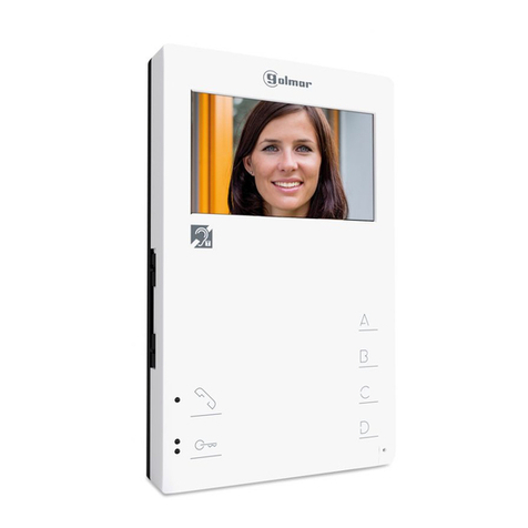
MONITOR ART 7W / /ART MONITOR MONITEUR ART7W 7W
S5110/ 7WART 5
Instalación
Installation
Installation
MONITOR ART 7W / /ART MONITOR MONITEUR ART7W 7W
ALIMENTADOR FA-G2+ / /FA-G2+ POWER SUPPLY ALIMENTATION FA-G2+ FA-G2+/VOEDING
Installatie
Instalación / / / /Installation Installation Instal Instalalatie ção
4. Bevestig de verwijderbare aansluitpunten op de monitor en plaats de monitor vervolgens
vóór de montageplaat, in de bevestigingshaken. Schuif vervolgens de monitor naar
beneden totdat deze stevig op de montageplaat is bevestigd.
Vermijd plaatsen in de buurt van warmtebronnen, stoffig of rokerig ruimtes. .
1. Plaats de bonenzijde van de monitor op een hoogte van 1,65 m.
2. Bij gebruik van een ingebouwde doos, zorg dan dat deze overeenkomen met de gaten van
de montageplaat. Als u de montageplaat liever direct aan de muur bevestigt, boor dan vier
gaten van 6 mm op de aangegeven punten (A); steek de meegeleverde pluggen erin en
schroef de basis erin.
3. Leid de installatiekabels door het middengat en sluit deze aan op de verwijderbare
aansluitklemmen volgens de instructies in de installatieschema's. Voordat u de verwijderbare
connectoren op de monitor aansluit, stelt u de dip-schakelaar in volgens de installatieschema’s.
Evite emplazamientos cercanos a fuentes de calor, polvorientos o con mucho humo. Para una
correcta instalación, utilice la plantilla suministrada.
1. Ubique la parte superior de la plantilla a una altura de 5 .1,6 m
2. Si va a utilizar una caja de empotrar para pasar los cables, hágala coincidir con los agujeros
correspondientes al modelo de caja escogido y fije la regleta. Si prefiere fijar la regleta
directamente sobre la pared, realice cuatro agujeros de 6mm en los puntos indicados (A);
coloque los tacos suministrados y atornille la regleta.
3. Pase los cables de instalación a través del agujero central y conéctelos a los terminales
extraibles siguiendo las indicaciones de los esquemas de instalación.Antes de conectar los
terminales extraibles al monitor, configure el interruptor siguiendo los esquemas de
instalación.
4. Conecte los terminales extraibles al monitor y coloque el monitor frontalmente a la regleta,
haciendo coincidir los anclajes. Desplace el monitor hacia abajo para fijarlo.
4. Connect the wiring connectors to the monitor and place the monitor front to the bracket,
matching the slots. Move the monitor down to fix it.
2. If you are going to use an embedding box to pass the cables, match it with the holes
corresponding to the chosen box model and fix the b . If you prefer to fix the
directly on the wall, make four 6mm holes at the indicated points ; insert the supplied
plugs and screw the .
racket bracket
(A)
bracket
3. Pass the installation cables through the central hole and connect them to the removable
wiring connectors following the indications of the installation diagrams. Before connecting
the wiring connectors to the monitor, set the configuration switch as indicated on the
installation diagrams.
Avoid locations near heat sources, dusty or with a lot of smoke. For a correct installation, use
the supplied template.
1. Locate the top of the template at a height of 1.65m.
Éviter les emplacements trop proches d'une source de chaleur, poussiéreux ou exposés à la
fumée. Pour une installation correcte, utilisez le gabarit fourni.
1. Localisez le haut du gabarit à une hauteur de 1,65 m.
2. Si vous utilisez un boîtier encastré pour faire passer les câbles, faites correspondre les trous
correspondant au modèle de boîtier choisi et fixez l’etrier. Si vous préférez fixer l’etrier
directement au mur, faites quatre trous de 6 mm aux points indiqués ; insérez les
chevilles fournies et vissez le bornier.
(A)
3. Faites passer les câbles d’installation par le trou central et connectez-les aux terminaux
amovibles en respectant les indications des schémas d’installation. Avant de connecter les
terminaux amovibles au moniteur, configurez l’interrupteur en suivant les schémas d'installation.
4. Connectez les terminaux amovibles au moniteur, puis installez le moniteur face à l'étrier en
veillant à faire correspondre les le moniteur vers le bas jusqu'à le
moniteur soit fermement fixé sur l'étrier
ancrages. Glisser
-La instalación y manipulación debe ser realizada por personal autorizado y en ausencia de
corriente eléctrica. La normativa vigente obliga a proteger el alimentador con un interruptor
magnetotérmico. No quite la tapa de protección sin antes desconectar el alimentador de la
corriente, y vuélvala a colocar una vez finalizadas todas las conexiones.
-The installation and manipulation must be carried out by authorized personnel. urrent
regulations require to protect the power supply with a circuit breaker. o not remove the
protection cover without first disconnecting the power supply. Re-install it once all
connections are complete
C
D
.
-L'installation et la manipulation doivent être effectuées par du personnel autorisé. Les
réglementations en vigueur exigent de protéger l'alimentation avec un disjoncteur. Ne retirez
pas le capot de protection sans avoir au préalable débranché l'alimentation. Réinstallez-le une
fois toutes les connexions terminées.
Instale el alimentador en un lugar seco, protegido y ventilado. Bajo ningún concepto obstruya
las rejillas de ventilación. Utilice una guía para su fijación .DIN 46277 (8 elementos)
Install the power supply in a dry, protected and ventilated place. Under no circumstances
obstruct the ventilation grilles. Use a 46277 guide for fastening (8 elements).DIN
Instalação
Evite locais próximos de fontes de calor, pulverulentos ou com muito fumo. Para uma
instalação correta, use o modelo fornecido.
2. Se você for usar uma caixa embutida para passar os cabos, combine-a com os orifícios
correspondentes ao modelo de caixa escolhido e fixe a . Se preferir fixar a
diretamente na parede, faça quatro furos de 6 mm nos pontos indicados ; insira os plugues
fornecidos e aparafuse a ba .
base base
(A)
se
4. Conecte os terminais removíveis ao monitor, depois coloque o monitor em frente da base,
fazendo coincidir os ganchos de fixação. Seguidamente desloque o monitor para baixo até
ficar bem montado na base.
1. Localize a parte superior do modelo a uma altura de 1,65m.
3. Passe os cabos de instalação pelo orifício central e conecte-os aos terminais removíveis
seguindo as indicações dos diagramas de instalação. Antes de conectar os terminais
removíveis ao monitor, configure o interruptor seguindo os diagramas de instalação.
S5110/ 7WART 7
S5110/ 7WART 6
ALIMENTADOR FA-G2+ / /FA-G2+ POWER SUPPLY ALIMENTATION FA-G2+ FA-G2+/VOEDING
4 monitores_2 placas / / (A)4 monitors_2 door panels 4 monitoren en 2 deurpanelen
BUS (M) BUS PL( )
ON
1 2 3 4
ON
1 2 3 4
ON
1 2 3 4 5 6 7 8
ON
1 2 3 4 5 6 7 8
LN
ON
1 2 3 4 5 6 7 8
12
BUS BUS BUS BUS BUS BUS BUS BUS BUS BUS
M1 S1 S3
100~240V ac
BUSBUS BUSBUS
BUS BUS BUS BUSBUS BUS BUS BUS
BUS (M) BUS PL( )
ON
1 2 3 4
ON
1 2 3 4
ON
1 2 3 4 5 6 7 8
ON
1 2 3 4 5 6 7 8
ON
1 2 3 4 5 6 7 8
ON
1 2 3 4 5 6 7 8
LN
M1
12
BUS IN BUS IN
BUS out A BUS out B BUS out C BUS out D
D4L-ART
ON
4 monitores_2 placas / / (B)4 monitors_2 door panels 4 monitoren en 2 deurpanelen
S1 S2 S3
100~240V ac
Instalación / / / /Installation Installation Instal Instalalatie ção
Cable A B C
2 x 0,75mm² ( 18)AWG 30 m 30 m 15 m
60 m 60 m 30 m
60 m 60 m 30 m
CAT5 (*)
RAP GTWIN HF- /
Utilisez deux paires torsadées pour chaque ligne de bus.
Use dois pares trançados para cada linha de bus.
Distance between power supply and the farthest door panel.
Distância entre o alimentador e a placa mais distante.
Distance between power supply and the farthest monitor (or video distributor).
A Distancia entre el alimentador y la placa más lejana..
B Distancia entre el alimentador y el monitor (o distribuidor) más lejano..
C Distancia entre un distribuidor y el monitor más lejano conectado a una de sus salidas..
Distance entre un répartiteur vidéo et le moniteur le plus éloigné connecté à une de ses sorties.
Afstand tussen videosplitter en verste monitor aangesloten op de splitter.
Distance e tre l’alimentation et le moniteur (ou répartiteur vidéo) le plus éloignée.n
Distância entre um distribuidor e o monitor mais distante conectado a uma de suas saídas.
( )* Utilizar dos pares trenzados para cada línea de bus.
Use two twisted pairs for each bus line.
Afstand tussen voeding en verste buitendeurpaneel
Distância entre o alimentador e o monitor (ou distribuidor) mais distante.
Distance entre l’alimentation et la plaque de rue la plus éloignée.
Afstand tussen voeding en verste monitor.
Distance between a video distributor and the farthest monitor connected to one of its outputs.
Gebruik een getwiste paar voor de BUS kabel.
ESQUEMAS // / /DIAGRAMS SCHÉMAS SCHEMA’S DIAGRAMAS
Secciones y distancias / /Cross sections and distances Sections et distances
Installez l’alimentation dans un endroit sec, protégé et ventilé. En aucun cas obstruer les
grilles de ventilation. Utilisez le guide 46277 pour la fixation (8 éléments).DIN
-De installatie moeten worden uitgevoerd door een erkend installateur. De huidige
voorschriften vereisen dat de stroomvoorziening wordt beschermd door een groepenkast
automaat. Verwijder de beschermkap niet zonder eerst de stroomtoevoer af te schakelen.
Plaats deze terug zodra alle verbindingen voltooid zijn.
Instale em um local seco, protegido e ventilado. Sob nenhuma circunstância
obstruir as grades de ventilação. Use o guia 46277 para fixação (8 elementos).
o alimentador
DIN
-A instalação e o manuseio devem ser realizados por pessoal autorizado e na ausência de
energia elétrica. Os regulamentos atuais exigem proteger o alimentador com um interruptor
magnetotérmico. Não remova a tampa protetora sem antes desconectar a energia elétrica
e depois reinstalá-la assim que todas as conexões forem concluídas.
Installeer de voeding op een droge, beschermde en geventileerde plaats. Blokkeer in geen
geval de ventilatieroosters. Gebruik een DIN 46277-rail voor bevestiging (8 elementen).
1 monitor_1 placa / /1 monitor_1 door panel 1 monitor met 1 deurpaneel
BUS (M) BUS PL( )
ON
1 2 3 4
ON
1 2 3 4 5 6 7 8
LN
1
BUS BUS BUS BUS
100~240V ac
M1
FA-G2+
FA-G2+
FA-G2+
ESQUEMAS / / SCHÉMAS / /DIAGRAMS SCHEMA’S DIAGRAMAS

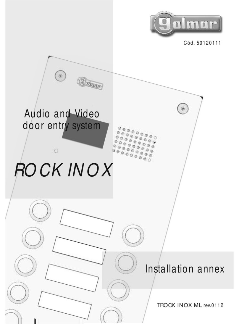
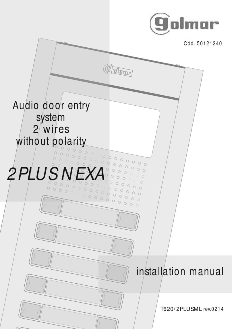
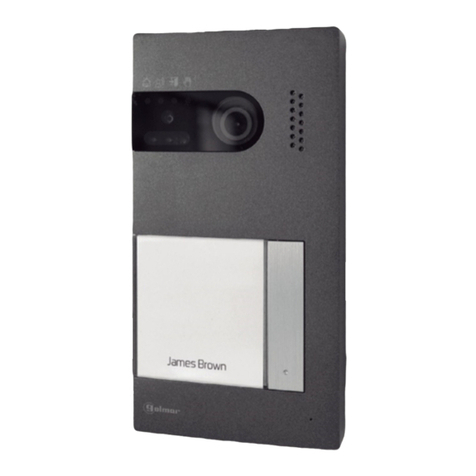
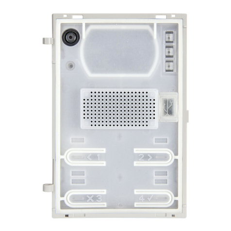
Other manuals for Soul kit

3

This manual suits for next models

1

Other golmar Intercom System manuals

golmar T22ML Surf User manual

golmar

golmar T22ML Surf User manual

golmar KIT SOUL S4110 ART 1 G2+/T-ART G2+ User manual

golmar

golmar KIT SOUL S4110 ART 1 G2+/T-ART G2+ User manual

golmar SOUL 7W KIT User manual

golmar

golmar SOUL 7W KIT User manual

golmar G2+ User manual

golmar

golmar G2+ User manual

golmar S5110/ART 7 User manual

golmar

golmar S5110/ART 7 User manual

golmar 295 Series User manual

golmar

golmar 295 Series User manual

golmar 7W/G2+ User manual

golmar

golmar 7W/G2+ User manual

golmar Stadio Plus T500SE ML User manual

golmar

golmar Stadio Plus T500SE ML User manual

golmar IP ART 7/G+/48 User manual

golmar

golmar IP ART 7/G+/48 User manual

golmar Tekna HF Plus User manual

golmar

golmar Tekna HF Plus User manual

golmar Stadio Plus T555ML User manual

golmar

golmar Stadio Plus T555ML User manual

golmar CE-990 Plus User manual

golmar

golmar CE-990 Plus User manual

golmar Nexa 90 User manual

golmar

golmar Nexa 90 User manual

golmar Jazz GB2 User manual

golmar

golmar Jazz GB2 User manual

golmar T-590VD User manual

golmar

golmar T-590VD User manual

golmar T-540 Uno User manual

golmar

golmar T-540 Uno User manual

golmar TKIT632 User manual

golmar

golmar TKIT632 User manual

golmar SV-370S User manual

golmar

golmar SV-370S User manual

golmar Plus Nexa User manual

golmar

golmar Plus Nexa User manual

golmar TSzena ML User manual

golmar

golmar TSzena ML User manual

golmar GB2 Vesta 2 User manual

golmar

golmar GB2 Vesta 2 User manual

golmar TEKNA-S GTWIN User manual

golmar

golmar TEKNA-S GTWIN User manual

golmar T500ML User manual

golmar

golmar T500ML User manual

golmar Tekna S Plus User manual

golmar

golmar Tekna S Plus User manual

Popular Intercom System manuals by other brands

2N Indoor View user manual

2N

2N Indoor View user manual

HME Clear-Com Encore MS-702 instruction manual

HME

HME Clear-Com Encore MS-702 instruction manual

Sysd ST-VD901 instruction manual

Sysd

Sysd ST-VD901 instruction manual

XONTEL XT-13P user manual

XONTEL

XONTEL XT-13P user manual

RTS BP-325 user manual

RTS

RTS BP-325 user manual

USG EquiCoach 4 Quick setup guide

USG

USG EquiCoach 4 Quick setup guide

Slinex ML-15HR user manual

Slinex

Slinex ML-15HR user manual

Vook VHD670 Operation and installation manual

Vook

Vook VHD670 Operation and installation manual

SynerTech 1 family Installation and operation manual

SynerTech

SynerTech 1 family Installation and operation manual

Technaxx TX-59+ user manual

Technaxx

Technaxx TX-59+ user manual

Ultra Secure ULTRACOM 3 manual

Ultra Secure

Ultra Secure ULTRACOM 3 manual

Clear-Com ICS-2003 instruction manual

Clear-Com

Clear-Com ICS-2003 instruction manual

Sonetics SON201 Series Installation & operation manual

Sonetics

Sonetics SON201 Series Installation & operation manual

Hyundai Telecom HA-201 Operating	 instruction

Hyundai Telecom

Hyundai Telecom HA-201 Operating instruction

Thodukonics N62DP owner's manual

Thodukonics

Thodukonics N62DP owner's manual

Bpt YVL200 UK Instructions for use and installation

Bpt

Bpt YVL200 UK Instructions for use and installation

Radio Shack 20-285 owner's manual

Radio Shack

Radio Shack 20-285 owner's manual

Chamberlain CAPXS installation manual

Chamberlain

Chamberlain CAPXS installation manual

manuals.online logo
manuals.online logoBrands
  • About & Mission
  • Contact us
  • Privacy Policy
  • Terms and Conditions

Copyright 2025 Manuals.Online. All Rights Reserved.