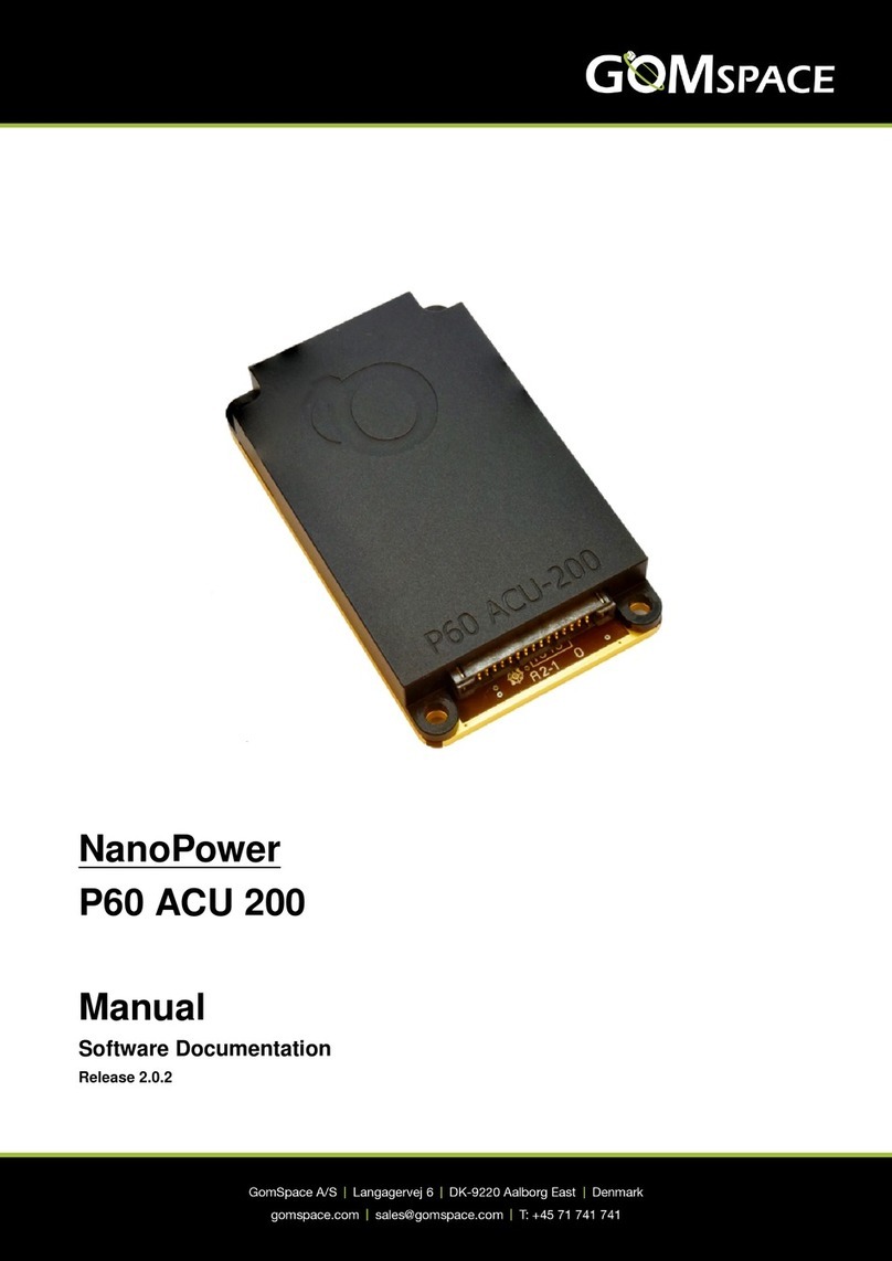
GOMspace NanoPower P60 Dock User manual

NanoPower
P60 Dock
Manual
Software Documentation

NanoPower P60 Dock
July 14, 2017
gs-man-nanopower-p60-dock-2.1
Table of Contents
1 Change Log 3
2 Introduction 4
2.1 Unpacking and Handling Precautions ................................. 4
3 Overview 5
4 Command Interface 6
4.1 Global Settings .............................................. 6
5 Operation 7
5.1 Board Parameters ............................................ 7
5.2 Configuration Parameters ........................................ 7
5.3 Calibration Parameters ......................................... 10
5.4 Telemetry Parameters .......................................... 10
5.5 Configuration ............................................... 11
5.6 Ground Watchdog ............................................ 11
5.7 Bus Watchdogs ............................................. 12
5.8 CSP Watchdogs ............................................. 12
5.9 Antenna Deployment .......................................... 12
6 Client API 13
6.1 CSP Port numbers ............................................ 13
6.2 Get and Set Configuration Parameters ................................ 13
6.3 Retriving Housekeeping Parameters .................................. 14
6.4 Reset Ground Watchdog Timer .................................... 15
7 Parameter Tables 17
7.1 Table 0: Board Parameters ....................................... 18
7.2 Table 1: Configuration Parameters ................................... 19
7.3 Table 2: Calibration Parameters .................................... 21
7.4 Table 4: Telemetry ............................................ 22
© 2016 GomSpace Aps 2

NanoPower P60 Dock
July 14, 2017
gs-man-nanopower-p60-dock-2.1
1. Change Log
Date Revision Author Description
14-06-2016 1.0 KBA Initial version 1.0
© 2016 GomSpace Aps 3

NanoPower P60 Dock
July 14, 2017
gs-man-nanopower-p60-dock-2.1
2. Introduction
The GomSpace NanoPower P60 EPS is a flexible and modular system to rapidly implement power supply
systems based on customer requirements. The P60 Dock is part of the NanoPower P60 EPS modular power
supply system.
This manual describes the P60 Dock firmware version 2.1:
• Command Interface
• CSP Client API
• Parameter Tables
2.1 Unpacking and Handling Precautions
Warning The P60 Dock is an ESD sensitive device. Proper precautions must be observed during
the handling of the device.
Please use an ESD mat and a wrist strap as a minimum. Please wear gloves to avoid fingerprints on the
anodized aluminum parts, as these are particularly difficult to rinse off. If any cleaning of the parts are required
prior to flight, use only ESD safe cleaning methods and a neutral, non-reactive, IPA solvent.
© 2016 GomSpace Aps 4

NanoPower P60 Dock
July 14, 2017
gs-man-nanopower-p60-dock-2.1
3. Overview
The P60 Dock can be operated through the Cubesat Space Protocol (CSP) over CAN, I2C or serial port. This
integrates well with other GomSpace products, and GomSpace provides a client library for commanding the P60
Dock from other systems running CSP. Refer to the Client API page for documentation of the client library API.
For integration and testing purposes, a command line interface is also available as explained in Command
Interface. The command line interface uses the client API internally, so command names generally reflects the
API function names.
The block diagram below shows the different P60 Dock modules.
Fig. 3.1: P60 Dock Block Diagram
© 2016 GomSpace Aps 5

NanoPower P60 Dock
July 14, 2017
gs-man-nanopower-p60-dock-2.1
4. Command Interface
For testing and debugging purposes, the P60 Dock can be operated using the GomSpace Shell (GOSH) in-
terface. The console interface is available in the PJ and P2 connector. The serial connection is 8 databits, 1
stopbit, no parity at 500000 baud. On Linux, the serial connection can be opened using the minicom or tio tools
(tio was formerly known as gotty).
You can now execute commands in the GOSH command interpreter. An example command is cmp ident
which lists identification info of the current subsystem:
p60-dock # cmp ident
Hostname: p60-dock
Model: NanoPower P60 Dock
Revision: v0.1
Date: Nov 3 2015
Time: 09:53:08
A list of available commands can be shown by running the help command in GOSH. Pressing the tab key
automatically completes commands and subcommands, and shows a usage string. Commands specific to
the P60 Dock are assembled under the p60dock command group. These commands are also available in
csp-term for operating the P60 Dock via CSP:
p60-dock # p60dock
node Set node
timeout Set timeout in milliseconds
hk Get HK
gndwdt_clear Clear GND WDT
Note: All of the p60dock commands run over loopback CSP using GOSH command wrappers around the
Client API
4.1 Global Settings
The P60 Dock command line interface is written such that there are a few global variables that can be set first.
The default values of the variables are:
• The P60 Dock CSP address is set to 4.
• Timeout is set to 5000 ms.
These values can be set using the p60dock node <node> and p60dock timeout <timeout>. To show
the current setting, run each command without an argument.
© 2016 GomSpace Aps 6

NanoPower P60 Dock
July 14, 2017
gs-man-nanopower-p60-dock-2.1
5. Operation
The P60 Dock has three configuration parameter tables:
• Board parameters (table 0)
• Configuration parameters (table 1)
• Calibration parameters (table 2)
P60 Dock telemetry parameters are available in parameter table 4.
See Parameter Tables for details on the individual parameter tables.
5.1 Board Parameters
The Board parameters will normally be configured from factory.
If the P60 Dock has been ordered with RS422 interface, it will be enabled. This is done via parameter
rs422_mode set to 1. The default baud rate for RS422 USART is set at 115200. Supported baud rates
are 38400, 115200 and 500000. Baud rate is controlled by parameter rs422_speed. The RS422 USART
uses 8 bit, no parity and one stop-bit (8N1).
CSP address is controlled by parameter is csp_addr. The default CSP address is 4 for the P60 Dock.
5.2 Configuration Parameters
The P60 Dock has a total of 13 channels that all can be turned on and off. Each channel can be configured with
a name. Default names are listed in table below. Seven characters are available for channel names. Channel
names are set by parameter out_name[].
Table 5.1: P60 Dock Output channels
Channel Description Default name
0 X1 VCC x1_vcc
1 X2 VCC x2_vcc
2 X3 VCC x3_vcc
3 X4 VCC x4_vcc
4 X1 VBAT x1_vbat
5 X2 VBAT x2_vbat
6 X3 VBAT x3_vbat
7 X4 VBAT x4_vbat
8 STACK VBAT st_vbat
9 STACK 3.3V st_3v3
10 STACK 5V st_5v
11 GSSB 3.3V gs_3v3
12 GSSB 5V gs_5v
5.2.1 Channel Control
The 13 channels can all be turned on and off manually and/or automatically. From factory the P60 Dock will be
configured to turn on all mounted daughterboard modules in the following way:
© 2016 GomSpace Aps 7

NanoPower P60 Dock
July 14, 2017
gs-man-nanopower-p60-dock-2.1
1. VCC and VBAT for X1 - X4 are turned on automatically when the P60 Dock has completed boot sequence
2. All other channels are not turned on automatically
To turn a channel on or off manually, set the appropriate out_en[] parameter.
To turn a channel on manually with a delay, set the appropriate out_on_cnt[] parameter to turn the channel
on after X seconds. X must be larger than zero.
To turn a channel off manually with a delay, set the appropriate out_off_cnt[] parameter to turn the channel
off after X seconds. X must be larger than zero.
5.2.2 Battery Mode Dependant Output Control
The P60 Dock output channels can be turned on and off automatically depending on the battery mode (see
Battery Voltage Level).
Battery mode FULL
In battery mode FULL, all output channels are left unchanged.
Battery mode NORMAL
To turn a channel on automatically without delay when battery mode is NORMAL, set the appropriate
init_out_norm[] parameter to 1.
To turn a channel on automatically with a delay when battery mode is NORMAL, set the appropriate
init_on_dly[] parameter to turn the channel on after X seconds. X must be larger than zero. In this case
the init_out_norm[] parameter should be 0, otherwise the channel will turn on immediately when battery
mode is NORMAL.
To turn a channel off automatically with a delay when battery mode is NORMAL, set the appropriate
init_off_dly[] parameter to turn the channel off after X seconds. X must be larger than zero. In this
case the init_out_norm[] parameter should be 1 or the init_on_dly[] parameter should have a value
smaller than the init_off_dly[] parameter.
Battery mode SAFE
To keep a channel turned on if battery mode is SAFE mode, set the appropriate init_out_safe[] parameter
to 1 to keep the channel on when battery mode is SAFE. Otherwise the channel will be turned off when entering
SAFE mode.
The parameters init_on_dly[] and init_off_dly[] are not used in battery mode SAFE.
Battery mode CRITICAL
In battery mode CRITICAL, all output channels will turned off automatically without any delay.
5.2.3 Current Limitation
All channels have two current limitation parameters, cur_lu_lim[] and cur_lim[].
The parameter cur_lu_lim[] is a hard limit, and if the channel consumes more than this limit it will be turned
off immediately. It will be turned on again automatically after 5 seconds.
The parameter cur_lim[] is a soft limit, meaning that if the channel over a period of time on average consumes
more than this limit it will be turned off. The average is calculated over time as an Exponential Moving Average
(EMA). The channel will be turned on again automatically after 5 seconds.
5.2.4 Battery Voltage Level
The P60 Dock has a software low voltage protection and will automatically turn channels on and off depending on
battery voltage level and a set of battery level configuration parameters (batt_max,batt_norm,batt_safe
© 2016 GomSpace Aps 8

NanoPower P60 Dock
July 14, 2017
gs-man-nanopower-p60-dock-2.1
and batt_crit). The software low voltage protection is a four state system with a CRITICAL, a SAFE, a
NORMAL and a FULL mode.
In normal mode everything is nominal but should the battery voltage drop below batt_safe, the P60 Dock will
change its output switch configuration to a safe mode configuration. This allows the P60 Dock to switch off of all
non-essential systems and leave a simple low power mode running.
Should the battery voltage continue to drop below batt_crit, the P60 Dock will switch off all channels.
The four battery voltage level parameters (batt_max,batt_norm,batt_safe and batt_crit) are each
configurable and must be set to match the battery and the channel control (see section Channel Control) must
be set accordingly to ensure that daughter boards are turned on/off as required by mission.
The following table shows the default settings for battery voltage levels.
Table 5.2: Recommended settings for battery voltage levels
Battery Pack Voltage 8 V 16 V 32 V
batt_max 8300 mV 16600 mV 32000 mV
batt_norm 7000 mV 14000 mV 28000 mV
batt_safe 6700 mV 13400 mV 26800 mV
batt_crit 6500 mV 13000 mV 26000 mV
5.2.5 Battery Pack
The P60 Dock must be configured with the battery pack type. The parameter batt_pack must be set with the
appropriate value for the batttery pack. The following table shows possible configuration values:
Table 5.3: P60 Dock Battery pack values
Battery pack value Description
0 None
1 Reserved
2 BP4 Battery Pack
3 BPX Battery Pack
5.2.6 Battery Heater
For the BP4 battery pack, it is possible to enable heater control. The heater mode bp_heat_mode parameter
controls how the battery heater is turned on and off. The following table shows possible configuration values:
Table 5.4: P60 Dock Battery heater control modes
Battery heater mode value Description
0 Heater always off
1 Heater on/off controlled by temperature thresholds
2 Heater always on
The heater on/off can be controlled by temperature thresholds by setting the bp_heat_high and
bp_heat_low parameters. The bp_heat_low parameter determines when to turn the heater on, i.e. when
the battery pack temperature goes below the bp_heat_low value, the battery heater turns on. Similar, the
© 2016 GomSpace Aps 9

NanoPower P60 Dock
July 14, 2017
gs-man-nanopower-p60-dock-2.1
bp_heat_high parameter determines when to turn the heater off, i.e. when the battery pack temperature goes
above the bp_heat_high value, the battery heater turns off.
Note: The bp_heat_high and bp_heat_low are set in 0.1 °C. E.g. a value of 50 means 5.0 °C.
5.3 Calibration Parameters
The P60 Dock has a set of calibration parameters for voltage and current measurements.
The calibration parameters are configured from factory and normally don’t need to be changed.
For voltages, there is a gain parameter. The gain is a floating-point number.
For currents, there is a gain and an offset parameter. The gain is a floating-point number. The offset is a signed
16-bit integer that controls the offset in mA.
The following table lists the default values for each calibration parameter:
Table 5.5: P60 Dock Calibration values
Name Voltage gain Current gain Current offset
X1 VCC n/a 1.0 0
X2 VCC n/a 1.0 0
X3 VCC n/a 1.0 0
X4 VCC n/a 1.0 0
X1 VBAT 25.0 1.0 0
X2 VBAT 25.0 1.0 0
X3 VBAT 25.0 1.0 0
X4 VBAT 25.0 1.0 0
STACK VBAT 25.0 1.0 0
STACK 3.3V n/a 1.0 0
STACK 5V n/a 1.0 0
GSSB 3.3V n/a 1.0 0
GSSB 5V n/a 1.0 0
VBAT 25.0 n/a n/a
VCC n/a 1.0 0
BATTERY 20.0 1.0 0
If the calibration value is n/a, it means that this value is not measured by the P60 Dock.
5.4 Telemetry Parameters
The P60 Dock will provide the measured voltage and current for each output channel in parameter v_out[]
and c_out[]. In case of over-current (see section Current Limitation) on an output channel, the latchup[]
parameter will increase by 1 each time an over-current is detected and the output channel is turned off by the
current monitoring function.
The state of each output channel is provided in the out_en[] parameter.
The battery voltage measured by the P60 Dock is provided in the parameter batt_v. The battery voltage is
monitored and the battery state is provided in the parameter batt_mode. The batt_mode can have one of
four values:
© 2016 GomSpace Aps 10

NanoPower P60 Dock
July 14, 2017
gs-man-nanopower-p60-dock-2.1
Table 5.6: P60 Dock Battery mode values
Battery Mode value Battery Mode description
1 CRITICAL
2 SAFE
3 NORMAL
4 FULL
The battery current is also measured and is provided in the parameter batt_c.
Temperature of the P60 Dock is measured in two locations on the module and is available in parameter temp[].
5.5 Configuration
The P60 Dock module has two sets of configuration, the running configuration and the default configuration.
The default configuration is a fallback configuration that will be restored automatically if the ground watchdog is
triggered (see Ground Watchdog)
The P60 Dock has a set of commands to manage the configuration:
p60-pdu # config
status Show FRAM Lock status
lock Lock FRAM upper tables 0x1000 to 0x1800
unlock Unlock FRAM upper tables 0x1000 to 0x1800
gnd_wdt Get or set gnd wdt timeout value
update_default Update default factory settings in FRAM
verify_default Verify default factory settings in FRAM
5.6 Ground Watchdog
The P60 Dock module has a ground watchdog that needs to be reset at least every 48 hours if enabled. The
purpose of the ground watchdog is to enable the P60 Dock to revert to the default configuration if for some
reason the running configuration prevents the P60 Dock from operating.
If the ground watchdog is triggered, the P60 Dock will restore to the default configuration and then do a reset of
the P60 Dock.
To enable the ground watchdog and set the timeout value, run the following command form the GOSH terminal:
config gnd_wdt <timeout in seconds>
The minimum value is 172800 seconds (48 hours). The maximum value 31536000 seconds (365 days). To
disable the ground watchdog, set the timeout to 0 seconds.
Note: The P60 Dock will restore to the default configuration and then do a reset of the P60 Dock and all
mounted daughter baords if the ground watchdog is triggered.
5.6.1 Propagating the Ground Watchdog Reset
The P60 Dock has an optional feature that allows to propagate the ground watchdog reset message to all P60
daughter boards.
The is achieved by setting the p60acu_addr[] and p60pdu_addr[] parameters to the CSP addresses of
the P60 daughter boards. E.g if the P60 Dock has a P60 ACU-200 and tow P60 PDU-200 daughter boards
with CSP addresses 2, 3 and 6 respectively, the p60acu_addr[] and p60pdu_addr[] should be set to [2 0]
and the p60pdu_addr[] should be set to [3 6 0 0]. When the ground wtachdog is reset on the P60 Dock, the
© 2016 GomSpace Aps 11

NanoPower P60 Dock
July 14, 2017
gs-man-nanopower-p60-dock-2.1
P60 Dock will forard the ground watchdog reset message to P60 ACU-200 on CSP address 2 and the two P60
PDU-200 on CSP address 3 and 6.
Using the ground watchdog reset propagation, it is only necessary to sen d the gorund watchdog reset message
to the P60 Dock.
5.7 Bus Watchdogs
The P60 Dock module has two satellite bus watchdogs, one for I2C and one for CAN, which allows the P60 Dock
to monitor if the satellite bus is operational. Both satellite bus watchdogs can be enabled or disabled and has
individual timeout values, wdt_i2c and wdt_can respectively. The P60 Dock can be configured to reboot if the
satellite bus watchdog is triggered, this is controlled by the wdt_i2c_rst and wdt_can_rst, respectively.
When configured and enabled (wdt_i2c_rst/wdt_can_rst is 1 and wdt_i2c/wdt_can > 0), the P60 Dock
will reboot if no traffic is observed on the satellite bus for wdt_i2c/wdt_can seconds.
Note: The satellite bus watchdogs does not run when the battery mode is CRITICAL.
5.8 CSP Watchdogs
The P60 Dock module has two CSP watchdogs that allows to actively monitor two different nodes on the CSP
satellite bus.
If a CSP address is configured for wdt_csp_addr[], the P60 Dock will actively monitor the connectivity to
each of these systems with a ping packet each wdt_csp[] seconds. If wdt_csp_ping[] consecutive pings
are lost (maximum allowed response time is 30 ms), the corresponding power channel wdt_csp_chan[] is
power cycled with a 5 second off time.
The CSP watchdogs will only run if the configured output channel wdt_csp_chan[] is on.
5.9 Antenna Deployment
The P60 Dock module has support for NanoCom ANT6 and NanoCom AR6 deployment.
To enable deployment, it is required to set the GSSB I2C addresses of the ANT6 and/or the AR6 modules and
the deployment delay in parameter table 1. This is done by specifying the ANT6 I2C addresses in the parameter
ant6_addr and the AR6 I2C in the parameter ar6_addr.
It is also required to specify a delay after boot of the deployment. This is done by specifying the deployment
delay in seconds in the parameter depl_delay.
The status and result of the deployment is reflected in the ant6_depl and ar6_depl parameters in table 4
(Parameter Tables for details on the individual parameter tables).
© 2016 GomSpace Aps 12

NanoPower P60 Dock
July 14, 2017
gs-man-nanopower-p60-dock-2.1
6. Client API
The client API consists of a set of wrapper functions that simplify the CSP interface to the P60 Dock. These
functions are implemented in the p60dock_client.c file and can be integrated in custom code by including
the p60dock.h header file. The file p60dock_cmd.c implements the GOSH commands for the P60 Dock and
can be used as an additional reference for the use of the client API.
All the client functions specify a timeout argument that is used to specify the maximum number of milliseconds
to wait for a reply. The client interface automatically performs endian conversion to network byte order on all
arguments.
6.1 CSP Port numbers
The P60 Dock listens on the following CSP port numbers
Table 6.1: P60 Dock CSP port numbers
Port Name Description
0 CSP_CMP Control Port
1 CSP_PING Returns a copy of the packet received
2 CSP_PS Returns process list
3 CSP_MEMFREE Returns memory free
4 CSP_REBOOT Reboots subsystem
5 CSP_BUF_FREE Returns number of free buffers
6 CSP_UPTIME Returns subsystem uptime
7 P60_PORT_RPARAM Controls P60 Dock with parameter system (see Get and Set Con-
figuration Parameters)
9 P60_PORT_GNDWDT_RESET Used for ground watchdog reset (see Reset Ground Watchdog
Timer)
10 P60_PORT_CMDCONTROL Reserved for future use
For a description on how to use the CSP ports, please see libcsp manual. For a description on the parameter
system, please see libparam manual.
6.2 Get and Set Configuration Parameters
Getting and setting configuration parameters is done by using the remote parameter system API provided by
libparam.
Get a single configuration parameter from P60 Dock:
#include <p60dock.h>
/*Get enable status for X1 VCC */
uint8_t vcc_enable;
int res =rparam_get_single(&vcc_enable, /*Pointer to variable */
P60DOCK_OUT_EN(0), /*Logical address of parameter */
PARAM_UINT8, /*Parameter type */
1,/*Parameter size */
P60DOCK_PARAM, /*Parameter table id */
p60dock_node, /*P60 Dock csp node address */
P60_PORT_RPARAM, /*CSP port number */
1000); /*Timeout in milliseconds */
© 2016 GomSpace Aps 13

NanoPower P60 Dock
July 14, 2017
gs-man-nanopower-p60-dock-2.1
if (res >0) {
printf("Get VCC enable: %u\n", vcc_enable);
}
Set a single configuration parameter on P60 Dock:
#include <p60dock.h>
/*Enable X1 VCC */
uint8_t vcc_enable =1;
int res =rparam_set_single(&vcc_enable, /*Pointer to variable */
P60DOCK_OUT_EN(0), /*Logical address of parameter */
PARAM_UINT8, /*Parameter type */
1,/*Parameter size */
P60DOCK_PARAM, /*Parameter table id */
p60dock_node, /*P60 Dock csp node address */
P60_PORT_RPARAM, /*CSP port number */
1000); /*Timeout in milliseconds */
if (res >0) {
printf("Set vcc enable: %u\n", vcc_enable);
}
6.3 Retriving Housekeeping Parameters
Retrieving Housekeeping Parameters from the P60 Dock is provided by the p60dock_get_hk function.
int p60dock_get_hk(param_index_t *mem, uint8_t node, uint32_t timeout);
This function is used to retrieve housekeeping parameters from the P60 Dock. The housekeeping param-
eters are retrieved over CSP using the remote parameter system API provided by libparam. The function
p60dock_get_hk is basically a wrapper around the remote parameter system API. The input parameter mem
must be provided with a pointer to memory to hold the housekeeping parameters. The input parameter node
must provide the CSP node address of the P60 Dock and the timeout must provide the timeout in milliseconds.
An example is shown below.
#include <p60dock.h>
uint8_t p60dock_node =4;
uint8_t hk_mem[P60DOCK_HK_SIZE];
param_index_t p60dock_hk ={0};
p60dock_hk.physaddr =hk_mem;
if (!p60dock_get_hk(&p60dock_hk, p60dock_node, 1000)) {
printf("Error getting p60dock hk\n");
}else {
param_list(&p60dock_hk, 1);
}
Housekeeping parameters can also be retrieved directly from P60 Dock using the remote parameter system API
provided by libparam:
#include <p60dock.h>
uint8_t p60dock_node =4;
uint8_t out_en;
int res =rparam_get_single(&out_en, /*Pointer to variable */
P60DOCK_HK_OUT_EN(0), /*Logical address of parameter */
PARAM_UINT8, /*Parameter type */
1,/*Parameter size */
P60DOCK_HK, /*Parameter table id */
p60dock_node, /*P60 Dock csp node address */
P60_PORT_RPARAM, /*CSP port number */
© 2016 GomSpace Aps 14

NanoPower P60 Dock
July 14, 2017
gs-man-nanopower-p60-dock-2.1
1000); /*Timeout in milliseconds */
if (res >0) {
printf("Get out_en[0]: %u\n", out_en);
}
The above example retrieves a single parameter. It is possible to retrieve all Housekeeping parameters by
retrieving the entire table:
#include <p60dock.h>
uint8_t hk_mem[P60DOCK_HK_SIZE];
param_index_t node_hk ={0};
uint8_t p60dock_node =4;
node_hk.physaddr =hk_mem;
node_hk.table =p60dock_hk;
node_hk.mem_id =P60DOCK_HK;
node_hk.count =P60DOCK_HK_COUNT;
node_hk.size =P60DOCK_HK_SIZE;
int result =rparam_get_full_table(&node_hk,
p60dock_node,
P60_PORT_RPARAM,
node_hk.mem_id,
1000);
if (result != 0) {
printf("Error retrieving P60 Dock housekeeping\n");
}else {
printf("Retrieved P60 Dock housekeeping\n");
/*List all out_en[] values, using parameter name */
const param_table_t *param =param_find_name(node_hk.table,
node_hk.count,
"out_en");
if (param != NULL) {
for (uint8_t index =0; index <13; index++) {
/*Read parameter using name */
uint8_t *out_en =param_read_addr(param->addr +param->size *index,
&node_hk,
param->size);
printf("out_en[%d]: %u\n", index, *out_en);
}
}
/*List all c_out[] values, using parameter address */
param =param_find_addr(node_hk.table, node_hk.count, 0x0000);
if (param != NULL) {
for (uint8_t index =0; index <13; index++) {
/*Read parameter using address */
int16_t *c_out =param_read_addr(param->addr +param->size *index,
&node_hk,
param->size);
printf("c_out[%d]: %d mA\n", index, *c_out);
}
}
}
6.4 Reset Ground Watchdog Timer
The Ground Watchdog Timer is reset by a dedicated command to the P60 Dock. This can for example be used
as a ground communication watch dog, i.e. this command is issued to P60 Dock on each connection with the
ground station. If no communication has been received for a period of 48 hours P60 Dock will switch off and do
a reset back to default configuration.
© 2016 GomSpace Aps 15

NanoPower P60 Dock
July 14, 2017
gs-man-nanopower-p60-dock-2.1
The Ground Watchdog Timer on the P60 Dock is reset by sending a single byte with the value 0x78 to CSP port
P60_PORT_GNDWDT_RESET.
The P60 Dock is also capable of propagating the reset of the Ground Watchdog Timer to NanoPower P60 Input
and Output Modules by configuring the CSP addresses of the NanoPower P60 ACU and PDU modules in the
P60 Dock. See the Parameter Tables section for detail on this.
The following code will reset the Ground Watchdog Timer on the P60 Dock:
#include <p60dock.h>
int p60dock_gndwdt_clear(uint8_t node, uint32_t timeout) {
uint8_t magic =0x78;
return csp_transaction(CSP_PRIO_HIGH,
node,
P60_PORT_GNDWDT_RESET,
timeout,
&magic,
1,
NULL,
0);
}
© 2016 GomSpace Aps 16

NanoPower P60 Dock
July 14, 2017
gs-man-nanopower-p60-dock-2.1
7. Parameter Tables
A number of parameters on the P60 Dock can be adjusted through the GomSpace parameter system. The
parameters are divided across four tables depending on the parameter types.
Table 0 is used for system level parameters that are expected to stay fixed for the entire mission. Table 1 is used
for adjusting the operation and performance parameters. Table 2 is used for system level calibrartion parameters
that are expected to stay fixed for the entire mission. Table 4 is used to store telemetry data.
Table 7.1: P60 Dock Parameter tables
Table File Default Description
0 0 4 Board Configuration
1 1 5 Module Configuration
2 2 6 Calibration parameters
4--Telemetry Data
Through GOSH it is possible to list all parameters in a table by running the param list <table> command.
Here it shows the default configuration parameters:
p60-dock # param list 1
Parameter list 1:
0x0000 out_name STR "x1_vcc" "x2_vcc" "x3_vcc" "x4_vcc"
"x1_vbat" "x2_vbat" "x3_vbat" "x4_vbat"
"st_vbat" "st_3v3" "st_5v" "gs_3v3" "gs_5v"
0x0068 out_en U8 1 1 1 1 1 1 1 1 0 0 0 0 0
0x0076 out_on_cnt U16 0 0 0 0 0 0 0 0 0 0 0 0 0
0x0090 out_off_cnt U16 0 0 0 0 0 0 0 0 0 0 0 0 0
0x00AA init_out_norm U8 1 1 1 1 1 1 1 1 0 0 0 0 0
0x00B7 init_out_safe U8 1 1 1 1 1 1 1 1 0 0 0 0 0
0x00C4 init_on_dly U16 0 0 0 0 0 0 0 0 0 0 0 0 0
0x00DE init_off_dly U16 0 0 0 0 0 0 0 0 0 0 0 0 0
0x00F8 cur_lu_lim U16 2500 2500 2500 2500 2500 2500 2500 2500 2500 2500 2500
2500 2500
0x0112 cur_lim U16 2500 2500 2500 2500 2500 2500 2500 2500 2500 2500 2500
2500 2500
0x012C cur_ema U16 100 112 122 131 140 152 161 170 0 0 0 0 0
0x0148 cur_ema_gain FLT 0.500000
0x0150 vcc_vbat_link U8 0 0 0 0
0x014C vcc_link U8 0 0 0 0
0x0154 batt_pack U8 0
0x0156 batt_hwmax U16 16000
0x0158 batt_max U16 9000
0x015A batt_norm U16 8000
0x015C batt_safe U16 7000
0x015E batt_crit U16 6000
0x0160 bp_heat_mode U8 0
0x0162 bp_heat_low I16 0
0x0164 bp_heat_high I16 0
0x0168 wdt_i2c U32 0
0x0166 wdt_i2c_rst U8 0
0x016C wdt_can U32 0
0x0167 wdt_can_rst U8 0
0x0170 wdt_csp U32 60 60
0x0178 wdt_csp_ping U8 5 5
0x017A wdt_csp_chan U8 0 0
0x017C wdt_csp_addr U8 0 0
0x017E p60acu_chan U8 0 0
0x0180 p60acu_addr U8 0 0
© 2016 GomSpace Aps 17

NanoPower P60 Dock
July 14, 2017
gs-man-nanopower-p60-dock-2.1
0x0182 p60pdu_chan U8 0 0 0 0
0x0186 p60pdu_addr U8 0 0 0 0
0x018A conv_5v_en U8 0
0x0190 ant6_add U8 0 0
0x0194 ar6_addr U8 0 0 0 0
0x0198 depl_delay U32 0
A parameter is modified by first switching to its table with param mem <table> and then running param set
<parameter> <value>. E.g., to adjust the set the out_en value for channel 0 to 1, run the commands:
p60-dock # param mem 1
p60-dock # param set out_en[0] 1
p60-dock # param get out_en[0]
GET out_en[0] = 1
The updated parameter values are only valid until next reboot. To store a parameter permanently, the parameter
table must be stored to its matching file number (listed in the table above). To make our change to the vcc_en
value permanent, we then need to run param save <table> <file>:
p60-dock # param save 1 1
Table CRC 12813
Data CRC 57665
The parameter system protects the stored table with two checksums: one to protect the data itself against
corruption and one to ensure that the stored data matches the table structure.
System parameters in tables 0, 1 and 2 are saved in FRAM file numbers 0, 1 and 2 respectively.
The P60 Dock also has a default factory setting version of table 0, 1 and 2. The default factory settings are
stored in locked FRAM sectors and must be unlocked prior to saving the parameter table. This is done using
the config unlock command. After e.g. the param save 0 4 command has been executed, the FRAM
sectors can be relocked by calling config lock or by rebooting the system.
Note: As a safety measure, the config commands are only available through the GOSH interface and can
not be executed via CSP. It is therefore not possible to unlock and modify the table 0 parameters remotely. This
prevents accidental modification of e.g. the CSP address in orbit.
Telemetry data in table 4 is not saved to permanent storage and thus not backed by a file number or a default
factory setting.
7.1 Table 0: Board Parameters
Table 0 holds system level configuration. Modification of these parameters require a reboot of the system, before
they take effect.
Table 7.2: P60 Dock Parameter table 0: Board parameters
Name Address Type Index Default Value Unit Comment
uid 0x0000 STR (16) 0123456789ABCD Board UID
type 0x0010 U8 1 Board type
rev 0x0011 U8 0 Board revision
csp_addr 0x0012 U8 2 CSP address
i2c_addr 0x0013 U8 2 I2C address
i2c_speed 0x0014 U16 400 kbps I2C bitrate in kbps
can_speed 0x0016 U16 1000 kbps CAN bitrate in kbps
kiss_en 0x0018 U8 0 Enable KISS
rs422_mode 0x0019 U8 0 RS422 mode
rs422_speed 0x001C U32 115200 kbps RS422 bitrate in kbps
csp_rtable 0x0020 STR (96) Empty CSP routing table
© 2016 GomSpace Aps 18

NanoPower P60 Dock
July 14, 2017
gs-man-nanopower-p60-dock-2.1
7.2 Table 1: Configuration Parameters
Table 1 contains P60 Dock runtime configuration parameters.
Table 7.3: P60 Dock Parameter table 1: Configuration parameters (part 1/2)
Name Address Type Index Default Value Unit Comment
out_name 0x0000 STR [0..12] See below Output channel name (see below)
out_en 0x0068 U8 [0..12] 0 .. 0 Output channel enable (on/off)
out_on_cnt 0x0076 U16 [0..12] 0 .. 0 sec Output channel on delay in seconds
out_off_cnt 0x0090 U16 [0..12] 0 .. 0 sec Output channel off delay in seconds
init_out_norm 0x00AA U8 [0..12] 0 .. 0 Output channel on/off in battery normal
mode
init_out_safe 0x00B7 U8 [0..12] 0 .. 0 Output channel on/off in battery safe mode
init_on_dly 0x00C4 U16 [0..12] 0 .. 0 sec Output channel on initial delay
init_off_dly 0x00DE U16 [0..12] 0 .. 0 sec Output channel off initial delay
cur_lu_lim 0x00F8 U16 2500 .. 2500 mA Output channel instant latchup current limit
(mA)
cur_lim 0x0112 U16 2500 .. 2500 mA Output channel ema latchup current limit
(mA)
cur_ema 0x012C U16 0 .. 0 mA Output channel latest current ema value
(mA)
cur_ema_gain 0x0148 FLT 0.5 Output current ema gain
vcc_vbat_link 0x0150 U8 [0..3] 0 0 0 0 Output channel link VCC and correspond-
ing VBAT (0 or 1)
vcc_link 0x014C U8 [0..3] 0 0 0 0 Output channel linked VCC channel [0..3]
batt_pack 0x0154 U8 0 Battery Pack type (0=None, 2=BP4,
3=BPX)
batt_hwmax 0x0156 U16 16000 mV Battery HW max value (mV)
batt_max 0x0158 U16 9000 mV Battery full mode threshold value (mV)
batt_norm 0x015A U16 8000 mV Battery normal mode threshold value (mV)
batt_safe 0x015C U16 7000 mV Battery safe mode threshold value (mV)
batt_crit 0x015E U16 6000 mV Battery critical mode threshold value (mV)
bp_heat_mode 0x0160 U8 0 Battery heater mode (0=heater off, 1=on
when temperature below threshold,
2=heater always on)
bp_heat_low 0x0162 I16 0 0.1 °C Battery heater low threshold
bp_heat_high 0x0164 I16 0 0.1 °C Battery heater high threshold
© 2016 GomSpace Aps 19

NanoPower P60 Dock
July 14, 2017
gs-man-nanopower-p60-dock-2.1
Table 7.4: P60 Dock Parameter table 1: Configuration parameters (part 2/2)
Name Address Type Index Default Value Unit Comment
wdt_i2c 0x0168 U32 0 sec I2C WDT timeout value in seconds
wdt_i2c_rst 0x0166 U8 0 Reboot if I2C WDT expires (0/1)
wdt_can 0x016C U32 0 sec CAN WDT timeout value in seconds
wdt_can_rst 0x0167 U8 0 Reboot if CAN WDT expires (0/1)
wdt_csp 0x0170 U32 [0..1] 60 60 sec CSP watchdog ping interval in seconds
wdt_csp_ping 0x0178 U8 [0..1] 5 5 CSP watchdog failed ping limit
wdt_csp_chan 0x017A U8 [0..1] 0 0 Output channel to monitor via CSP
wdt_csp_addr 0x017C U8 [0..1] 0 0 CSP address to ping when monitoring out-
put channel via CSP
p60acu_chan 0x017E U8 [0..1] 0 0 P60 ACU module channels (for future use)
p60acu_addr 0x0180 U8 [0..1] 0 0 P60 ACU module addresses
p60pdu_chan 0x0182 U8 [0..3] 0 0 0 0 P60 PDU module channels (for future use)
p60pdu_addr 0x0186 U8 [0..3] 0 0 0 0 P60 PDU module addresses
conv_5v_en 0x018A U8 0 Enable 5 V converter manually (for test)
ant6_addr 0x0190 U8 [0..1] 0 0 ANT6 GSSB I2C addresses
ar6_addr 0x0194 U8 [0..3] 0 0 0 0 AR6 GSSB I2C addresses
depl_delay 0x0198 U32 0 sec Deployment delay after boot
The following table shows the output channel names for each Output channel index:
Table 7.5: P60 Dock Parameter table 1: Configuration parameters
Index Output channel name Description
0 .. 3 x1_vcc x2_vcc x3_vcc x4_vcc VCC for X1, X2, X3 and X4
4 .. 7 x1_vbat x2_vbat x3_vbat x4_vbat VBAT for X1, X2, X3 and X4
8 st_vbat Stack VBAT
9 st_3v3 Stack 3.3 V
10 st_5v Stack 5 V
11 gs_3v3 GSSB 3.3 V
12 gs_5v GSSB 5 V
© 2016 GomSpace Aps 20
Table of contents
Other GOMspace Computer Hardware manuals
Popular Computer Hardware manuals by other brands

Texas Instruments
Texas Instruments TSC2007EVM user guide

BCM
BCM NUC-TGU Quick reference guide

BOSER Technology
BOSER Technology HS-4700 manual

Tektronix
Tektronix TMSST1 instruction manual

Renesas
Renesas MCU Board for PC4400 Emulator System... user manual

MF DIGITAL
MF DIGITAL Scribe 9600 series Quick connect guide

XLR8
XLR8 MACh Speed G3 ZIF Installation and user manual

Texas Instruments
Texas Instruments EDMA3 user guide

Advantech
Advantech ADAM-3956 Startup manual

Sinevibes
Sinevibes Extremum user guide

Phytec
Phytec ATOM phyCORE-Z500P(T) Hardware manual

Boardcon Embedded Design
Boardcon Embedded Design Compact3566 user manual