GOMspace NanoPower P60 ACU 200 User manual

NanoPower
P60 ACU 200
Manual
Software Documentation
Release 2.0.2

Product name: NanoPower P60 ACU 200
Document No.: 1018434
Revision: 2.0.2
Author: Gomspace
Approved by: Gomspace
Approval date: 2023
Confidentiality Notice
This document is submitted for a specific purpose as aggred in writing and contains information, which is
confidential and proprietary. The recipient agrees by accepting this document, that this material will not be
used, transferred, reproduced, modified, copied or disclosed in whole or in part, in any manner or to any third
party, except own staff to meet the purpose for which it was submitted without prior written consent.
GomSpace © 2023

Table of Contents
1 Introduction 1
1.1 Unpacking and Handling Precautions . . . . . . . . . . . . . . . . . . . . . . . . . . . . . . . . . 1
2 Overview 2
3 Command Interface 3
3.1 GlobalSettings.............................................. 3
4 Operation 4
4.1 BoardParameters............................................ 4
4.2 ConfigurationParameters........................................ 4
4.2.1 ChargingControl ........................................ 4
4.2.2 Hardwareprotection ...................................... 5
4.3 CalibrationParameters ......................................... 5
4.4 TelemetryParameters.......................................... 6
4.5 Configuration............................................... 6
4.6 GroundWatchdog............................................ 6
5 Client API 8
5.1 CSPPortNumbers ........................................... 8
5.2 Get and Set Configuration Parameters . . . . . . . . . . . . . . . . . . . . . . . . . . . . . . . . 8
5.3 Retriving Housekeeping Parameters . . . . . . . . . . . . . . . . . . . . . . . . . . . . . . . . . . 9
5.4 ResetGroundWatchdogTimer .................................... 10
6 Parameter Tables 12
6.1 Table0:BoardParameters....................................... 13
6.2 Table 1: Configuration Parameters . . . . . . . . . . . . . . . . . . . . . . . . . . . . . . . . . . . 13
6.3 Table 2: Calibration Parameters . . . . . . . . . . . . . . . . . . . . . . . . . . . . . . . . . . . . 14
6.4 Table4:Telemetry............................................ 14
© 2023 GomSpace A/S. All printed copies, and all electronic copies and versions except the one accessible on
the GomSpace A/S server, are considered uncontrolled copies used for reference only.
i
Manual P60 ACU 200
22 March 2023
MAN 1018434 2.0.2

© 2023 GomSpace A/S. All printed copies, and all electronic copies and versions except the one accessible on
the GomSpace A/S server, are considered uncontrolled copies used for reference only.
ii
Manual P60 ACU 200
22 March 2023
MAN 1018434 2.0.2

1. Introduction
The GomSpace NanoPower P60 EPS is a flexible and modular system to rapidly implement power supply
systems based on customer requirements. The P60 ACU-200 is part of the NanoPower P60 EPS modular
power supply system.
This manual describes the P60 ACU-200 firmware version 2.0.2:
• Command Interface
• CSP Client API
• Parameter Tables
1.1 Unpacking and Handling Precautions
Warning The P60 ACU-200 is an ESD sensitive device. Proper precautions must be observed
during the handling of the device.
Please use an ESD mat and a wrist strap as a minimum. Please wear gloves to avoid fingerprints on the
anodized aluminum parts, as these are particularly difficult to rinse off. If any cleaning of the parts are required
prior to flight, use only ESD safe cleaning methods and a neutral, non-reactive, IPA solvent.
© 2023 GomSpace A/S. All printed copies, and all electronic copies and versions except the one accessible on
the GomSpace A/S server, are considered uncontrolled copies used for reference only.
1
Manual P60 ACU 200
22 March 2023
MAN 1018434 2.0.2

2. Overview
The P60 ACU-200 can be operated through the Cubesat Space Protocol (CSP) over CAN, I2C or serial port.
This integrates well with other GomSpace products, and GomSpace provides a client library for commanding
the P60 ACU-200 from other systems running CSP. Refer to the Client API page for documentation of the client
library API.
For integration and testing purposes, a command line interface is also available as explained in Command
Interface. The command line interface uses the client API internally, so command names generally reflects the
API function names.
The block diagram below shows the different P60 ACU-200 modules.
Fig. 2.1: P60 ACU-200 Block Diagram
© 2023 GomSpace A/S. All printed copies, and all electronic copies and versions except the one accessible on
the GomSpace A/S server, are considered uncontrolled copies used for reference only.
2
Manual P60 ACU 200
22 March 2023
MAN 1018434 2.0.2

3. Command Interface
For testing and debugging purposes, the P60 ACU-200 can be operated using the GomSpace Shell (GOSH)
interface. The console interface is available in the FPC Debug connector. The serial connection is 8 databits, 1
stopbit, no parity at 500000 baud. On Linux, the serial connection can be opened using the minicom or tio tools
(tio was formerly known as gotty).
You can now execute commands in the GOSH command interpreter. An example command is cmp ident
which lists identification info of the current subsystem:
p60-acu # cmp ident
Hostname: p60-acu
Model: NanoPower P60 ACU-200
Revision: v1.0
Date: Jun 10 2016
Time: 09:53:08
A list of available commands can be shown by running the help command in GOSH. Pressing the tab key
automatically completes commands and subcommands, and shows a usage string. Commands specific to
the P60 ACU-200 are assembled under the p60acu command group. These commands are also available in
csp-term for operating the P60 ACU-200 via CSP:
p60-acu # p60acu
node Set P60 ACU node address
timeout Set timeout in milliseconds
hk Retrieve and list all housekeeping parameters
gndwdt_clear Clear GND WDT
Note: All of the p60acu commands run over loopback CSP using GOSH command wrappers around the Client
API
3.1 Global Settings
The P60 ACU-200 command line interface is written such that there are a few global variables that can be set
first. The default values of the variables are:
• The P60 ACU-200 CSP address is set to 2.
• Timeout is set to 5000 ms.
These values can be set using the p60acu node <node> and p60acu timeout <timeout>. To show the
current setting, run each command without an argument.
© 2023 GomSpace A/S. All printed copies, and all electronic copies and versions except the one accessible on
the GomSpace A/S server, are considered uncontrolled copies used for reference only.
3
Manual P60 ACU 200
22 March 2023
MAN 1018434 2.0.2

4. Operation
The P60 ACU-200 has three configuration parameter tables:
• Board parameters (table 0)
• Configuration parameters (table 1)
• Calibration parameters (table 2)
P60 ACU-200 telemetry parameters are available in parameter table 4.
See Parameter Tables for details on the individual parameter tables.
4.1 Board Parameters
The Board parameters will normally be configured from factory.
The P60 ACU-200 does not support RS422 USART and rs422 should is set to 0.
CSP address is controlled by the parameter csp_addr. The default CSP address is 2 for the P60 ACU-200. If
multiple P60 ACU-200 modules are included, they will need to use different CSP address.
4.2 Configuration Parameters
The P60 ACU-200 power point tracking can either be Fixed or Tracking mode. This is controlled by the parameter
mppt_mode. To use Fixed mode, set mppt_mode to 2. To use Tracking mode, set mppt_mode to 1.
The P60 ACU-200 module has a total of 6 input channels.
For each input channel, the fixed power point voltage level used for charging the battery can be set by the
parameter vboost[].
In Fixed mode, the voltage is set to the value of parameter vboost[] and is not changed, except if battery
charge is completed.
In Tracking mode, the voltage is initialized to the value of parameter vboost[]. By tracking the power, the input
voltage is regulated to optimize the power generated by the input channels. It is possible to limit how much
the voltage is changed from the initial vboost value. This is controlled by the parameter max_dv. E.g. if the
vboost[] is set to 10000 mV and the max_dv is set to 5000 mV, the minimum voltage allowed will be 5000 mV
and the maximum will be 15000 mV.
In both modes, the lower limit for vboost[] is 4300 mV and the upper limit is 27000 mV.
4.2.1 Charging Control
When the battery becomes fully charged or near to fully charged, the charging will be regulated to avoid over
charging the battery. This is controlled by two parameters, vbat_max_hi and vbat_max_lo. When the
battery voltage exceeds vbat_max_lo, the P60 ACU-200 will regulate the voltage down slowly to reduce the
charging power. If the charging continues, even with reduced voltage, and the vbat_max_hi limit is reached,
the charging will be reduced to a minimum. Charging will not be resumed until the battery voltage drops below
vbat_max_lo. The following table lists the recommended values for vbat_max_hi and vbat_max_lo for 8,
16 and 32 V battery.
© 2023 GomSpace A/S. All printed copies, and all electronic copies and versions except the one accessible on
the GomSpace A/S server, are considered uncontrolled copies used for reference only.
4
Manual P60 ACU 200
22 March 2023
MAN 1018434 2.0.2

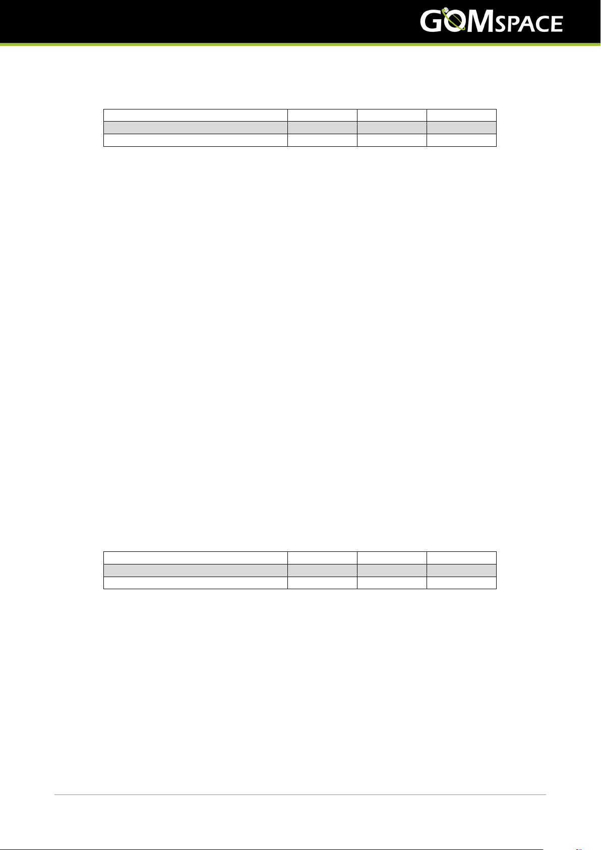
Table 4.1: Recommended settings for vbat_max_hi and
vbat_max_lo
Battery Pack Voltage 8 V 16 V 32 V
vbat_max_hi 8300 mV 16600 mV 33200 mV
vbat_max_lo 8150 mV 16300 mV 32600 mV
The ov_mode defines the photovoltaic converter behavior of the P60 ACU-200 when the battery is fully charged,
i.e. above the vbat_max_hi value.
When the battery voltage is above vbat_max_hi, the charging is minimised by setting the vboost voltage level
to the maximum value (27000 mV) or the minimum value (4300 mV), depending on the parameter ov_mode. If
ov_mode is 1, the vboost voltage level will be set to the minimum value (4300 mV). If ov_mode is 2, the vboost
voltage level will be set to the maximum value (27000 mV).
The default ov_mode is 2, defining that the photovoltaic input is open circuited when the battery is fully charged.
This mode is used on all spacecrafts with 8V, 16V and 32V battery pack, as long as each photovoltaic input
open circuit voltage is guaranteed to be below the maximum operation voltage of the battery pack. E.g. a 8V
battery pack requires an open circuit photovoltaic of no more than 8400 mV.
In special cases it may be desired to have a photovoltaic array with an open circuit input voltage slightly above
the max. battery voltage. If such a case cannot be avoided the ov_mode must be set to 1. When ov_mode
is 1, the photovoltaic input converter set point is as low as possible (4300 mV) when the maximum battery
voltage is reached. Note that in this case, a one-string photovoltaic panel (500 mA) still produces about 2.2 W.
It is recommended to have sufficient amount of subsystems powered ON in normal mode to avoid charging the
battery further.
If the battery is charged further, the P60 Dock will disconnect the battery as a final protection method until the
voltage is within safe operation again. Tripping the P60 Dock overvoltage battery protection may cause the
spacecraft to be power cycled, as the available photovoltaic input power might be insufficient.
4.2.2 Hardware protection
Both the P60 ACU-200 and the P60 Dock has hardware protection circuits to protect the battery. The P60
ACU-200 takes this into account when controlling the charging of the battery. If the battery voltage exceeds the
hardware protection high threshold, the charging will not resume until the battery voltage level has dropped be-
low the hardware protection low threshold. For security reasons, the hardware protection low and high threshold
are not configurable, but are listed here for reference:
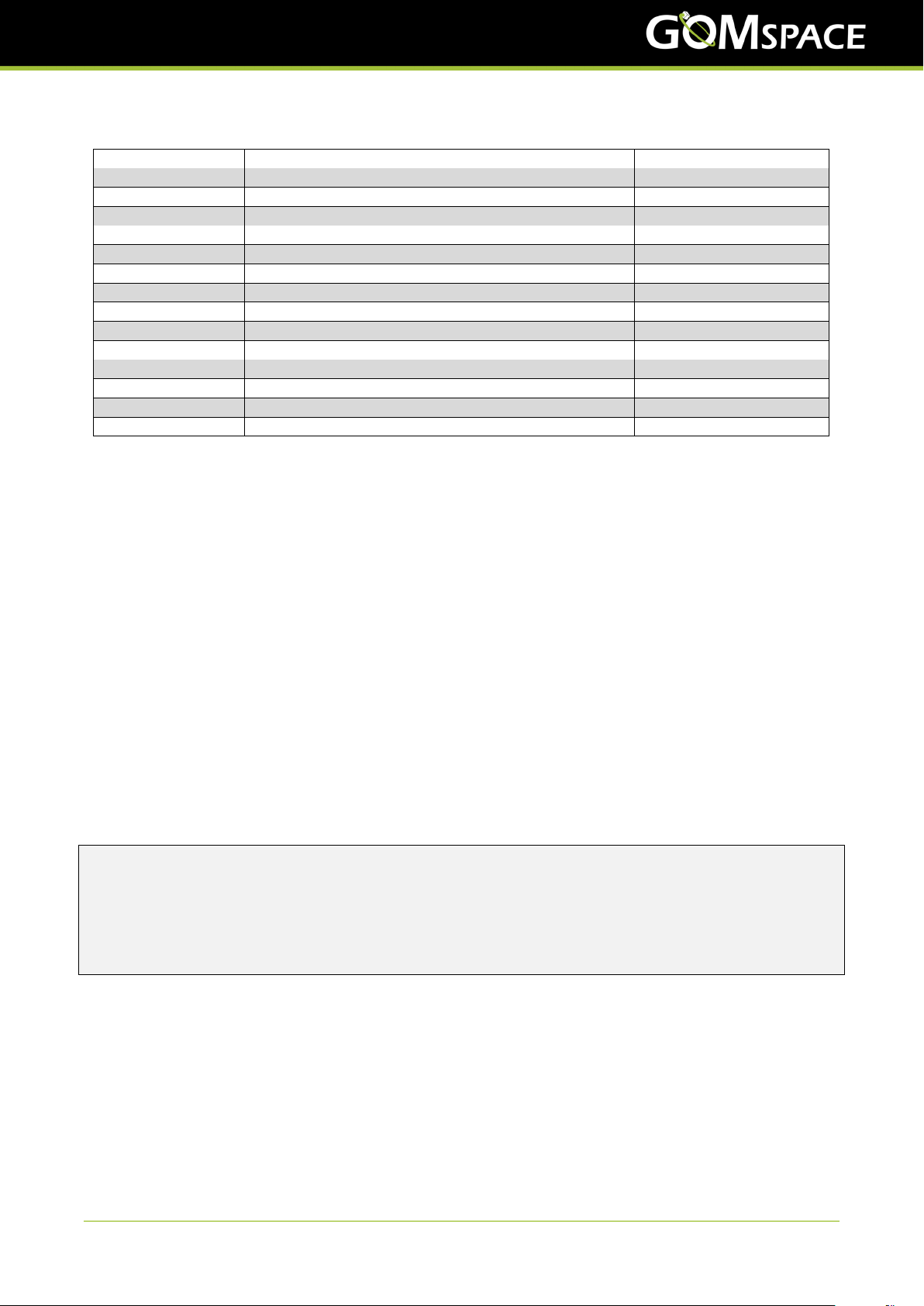
Table 4.2: Hardware protection thresholds for battery voltage
Battery Pack Voltage 8 V 16 V 32 V
High threshold 8400 mV 16800 mV 33600 mV
Low threshold 7625 mV 15250 mV 30500 mV
4.3 Calibration Parameters
The P60 ACU-200 module has a set of calibration parameters for voltage and current measurements.
The calibrations parameters are configured from factory and normally don’t need to be changed.
For voltages, there is a gain parameter. The gain is a floating-point number.
For currents, there is a gain and an offset parameter. The gain is a floating-point number. The offset is a signed
16-bit integer that controls the offset in mA.
The following table lists the default nominal values for each calibration parameter:
© 2023 GomSpace A/S. All printed copies, and all electronic copies and versions except the one accessible on
the GomSpace A/S server, are considered uncontrolled copies used for reference only.
5
Manual P60 ACU 200
22 March 2023
MAN 1018434 2.0.2

Table 4.3: P60 ACU-200 Calibration values
Name Voltage gain Current gain Current offset
V IN channel 0 11.0 1.0 0
V IN channel 1 11.0 1.0 0
V IN channel 2 11.0 1.0 0
V IN channel 3 11.0 1.0 0
V IN channel 4 11.0 1.0 0
V IN channel 5 11.0 1.0 0
VBAT 25.0 n/a n/a
VCC 3.2 n/a n/a
DAC channel 0 11.0 n/a n/a
DAC channel 1 11.0 n/a n/a
DAC channel 2 11.0 n/a n/a
DAC channel 3 11.0 n/a n/a
DAC channel 4 11.0 n/a n/a
DAC channel 5 11.0 n/a n/a
4.4 Telemetry Parameters
The P60 ACU-200 module will provide the measured input voltage and current for each input channel in param-
eters v_in[] and c_in[] respectively. The calculated power is also available in parameter power[]. The
charging voltage is provided in the parameter vboost[].
P60 ACU-200 also measures VCC and VBAT, they available in parameters vcc and vbat. Temperature of the
P60 ACU-200 is measured in three locations on the module and is available in parameter temp[].
The up time measured in seconds is available in the uptime parameter and the number of boots is available in
the bootcnt parameter (see also Parameter Tables for details on the telemetry parameters).
4.5 Configuration
The P60 ACU-200 module has two sets of configuration, the running configuration and the default configuration.
The default configuration is a fallback configuration that will be restored automatically if the ground watchdog is
triggered (see Ground Watchdog)
The P60 ACU-200 has a set of commands to manage the configuration:
p60-pdu # config
status Show FRAM Lock status
lock Lock FRAM upper tables 0x1000 to 0x1800
unlock Unlock FRAM upper tables 0x1000 to 0x1800
gnd_wdt Get or set gnd wdt timeout value
update_default Update default factory settings in FRAM
verify_default Verify default factory settings in FRAM
4.6 Ground Watchdog
The P60 ACU-200 module has a ground watchdog that needs to be activated at least every 48 hours if enabled.
The purpose of the ground watchdog is to enable the P60 ACU-200 to revert to the default configuration if for
some reason the running configuration prevents the P60 ACU-200 from operating.
If the ground watchdog is triggered, the P60 ACU-200 will restore to the default configuration and then do a
reset of the P60 ACU-200.
To enable the ground watchdog and set the timeout value, run the following command form the GOSH terminal:
© 2023 GomSpace A/S. All printed copies, and all electronic copies and versions except the one accessible on
the GomSpace A/S server, are considered uncontrolled copies used for reference only.
6
Manual P60 ACU 200
22 March 2023
MAN 1018434 2.0.2

config gnd_wdt <timeout in seconds>
The minimum value is 172800 seconds (48 hours). The maximum value 31536000 seconds (365 days). To
disable the ground watchdog, set the timeout to 0 seconds.
Note: The P60 ACU-200 will restore to the default configuration and then do a reset of the P60 ACU-200 if the
ground watchdog is triggered.
© 2023 GomSpace A/S. All printed copies, and all electronic copies and versions except the one accessible on
the GomSpace A/S server, are considered uncontrolled copies used for reference only.
7
Manual P60 ACU 200
22 March 2023
MAN 1018434 2.0.2

5. Client API
The client API consists of a set of wrapper functions that simplify the CSP interface to the P60 ACU-200. These
functions are implemented in the p60acu_client.c file and can be integrated in custom code by including the
p60acu.h header file. The file p60acu_cmd.c implements the GOSH commands for the P60 ACU-200 and
can be used as an additional reference for the use of the client API.
All the client functions specify a timeout argument that is used to specify the maximum number of milliseconds
to wait for a reply. The client interface automatically performs endian conversion to network byte order on all
arguments.
5.1 CSP Port Numbers
The P60 ACU-200 listens on the following CSP port numbers
Table 5.1: P60 ACU-200 CSP port numbers
Port Name Description
0 CSP_CMP Control Port
1 CSP_PING Returns a copy of the packet received
2 CSP_PS Returns process list
3 CSP_MEMFREE Returns memory free
4 CSP_REBOOT Reboots subsystem
5 CSP_BUF_FREE Returns number of free buffers
6 CSP_UPTIME Returns subsystem uptime
7 P60_PORT_RPARAM Controls P60 ACU with parameter system (see below)
9 P60_PORT_GNDWDT_RESET Used for ground watchdog reset
10 P60_PORT_CMDCONTROL Reserved for future use
For a description on how to use the CSP ports, please see libcsp manual. For a description on the parameter
system, please see libparam manual.
5.2 Get and Set Configuration Parameters
Getting and setting configuration parameters is done by using the remote parameter system API provided by
libparam.
Get a single configuration parameter from P60 ACU-200:
#include <p60acu.h>
uint16_t vboost;
int res =rparam_get_single(&vboost, /*Pointer to variable */
P60ACU_MPPT_VBOOST(0), /*Logical address of parameter */
PARAM_UINT16, /*Parameter type */
2,/*Parameter size */
P60ACU_PARAM, /*Parameter table id */
p60acu_node, /*P60 ACU csp node address */
P60_PORT_RPARAM, /*CSP port number */
1000); /*Timeout in milliseconds */
if (res >0) {
printf("Get vboost[0]: %u\n", vboost);
}
© 2023 GomSpace A/S. All printed copies, and all electronic copies and versions except the one accessible on
the GomSpace A/S server, are considered uncontrolled copies used for reference only.
8
Manual P60 ACU 200
22 March 2023
MAN 1018434 2.0.2

Set a single configuration parameter on P60 ACU-200:
#include <p60acu.h>
uint16_t vboost =5200;
int res =rparam_set_single(&vboost, /*Pointer to variable */
P60ACU_MPPT_VBOOST(0), /*Logical address of parameter */
PARAM_UINT16, /*Parameter type */
2,/*Parameter size */
P60ACU_PARAM, /*Parameter table id */
p60acu_node, /*P60 ACU csp node address */
P60_PORT_RPARAM, /*CSP port number */
1000); /*Timeout in milliseconds */
if (res >0) {
printf("Set vboost[0]: %u\n", vboost);
}
5.3 Retriving Housekeeping Parameters
Retrieving Housekeeping Parameters from the P60 ACU-200 is provided by the p60acu_get_hk function.
int p60acu_get_hk(param_index_t *mem, uint8_t node, uint32_t timeout);
This function is used to retrieve housekeeping parameters from the P60 ACU-200. The housekeeping pa-
rameters are retrieved over CSP using the remote parameter system API provided by libparam. The function
p60acu_get_hk is basically a wrapper around the remote parameter system API. The input parameter mem
must be provided with a pointer to memory to hold the housekeeping parameters. The input parameter node
must provide the CSP node address of the P60 ACU-200 and the timeout must provide the timeout in millisec-
onds. The following shows an example of this.
#include <p60acu.h>
uint8_t p60acu_node =2;
uint8_t hk_mem[P60ACU_HK_SIZE];
param_index_t p60acu_hk ={0};
p60acu_hk.physaddr =hk_mem;
if (!p60acu_get_hk(&p60acu_hk, p60acu_node, 1000)) {
printf("Error getting p60acu hk\n");
}else {
param_list(&p60acu_hk, 1);
}
Housekeeping parameters can also be retrieved directly from P60 ACU-200 using the remote parameter system
API provided by libparam:
#include <p60acu.h>
uint8_t p60acu_node =2;
uint16_t v_in;
int res =rparam_get_single(&vboost, /*Pointer to variable */
P60ACU_HK_V_IN(0), /*Logical address of parameter */
PARAM_UINT16, /*Parameter type */
1,/*Parameter size */
P60ACU_HK, /*Parameter table id */
p60acu_node, /*P60 ACU csp node address */
P60_PORT_RPARAM, /*CSP port number */
1000); /*Timeout in milliseconds */
if (res >0) {
printf("Get v_in[0]: %u\n", v_in);
}
© 2023 GomSpace A/S. All printed copies, and all electronic copies and versions except the one accessible on
the GomSpace A/S server, are considered uncontrolled copies used for reference only.
9
Manual P60 ACU 200
22 March 2023
MAN 1018434 2.0.2

The previous example retrieves a single parameter. It is possible to retrieve all Housekeeping parameters by
retrieving the entire table:
#include <p60acu.h>
uint8_t hk_mem[P60ACU_HK_SIZE];
param_index_t node_hk ={0};
uint8_t p60acu_node =2;
node_hk.physaddr =hk_mem;
node_hk.table =p60acu_hk;
node_hk.mem_id =P60ACU_HK;
node_hk.count =P60ACU_HK_COUNT;
node_hk.size =P60ACU_HK_SIZE;
int result =rparam_get_full_table(&node_hk,
p60acu_node,
P60_PORT_RPARAM,
node_hk.mem_id,
1000);
if (result != 0) {
printf("Error retrieving P60 ACU housekeeping\n");
}else {
printf("Retrieved P60 ACU housekeeping\n");
/*List all vboost[] values, using parameter name */
const param_table_t *param =param_find_name(node_hk.table,
node_hk.count,
"vboost");
if (param != NULL) {
for (uint8_t index =0; index <6; index++) {
/*Read parameter using name */
uint16_t *vboost =param_read_addr(param->addr +param->size *index,
&node_hk,
param->size);
printf("vboost[%d]: %u\n", index, *vboost);
}
}
/*List all c_in[] values, using parameter address */
param =param_find_addr(node_hk.table, node_hk.count, 0x0000);
if (param != NULL) {
for (uint8_t index =0; index <6; index++) {
/*Read parameter using address */
int16_t *c_in =param_read_addr(param->addr +param->size *index,
&node_hk,
param->size);
printf("c_in[%d]: %d mA\n", index, *c_in);
}
}
}
5.4 Reset Ground Watchdog Timer
The Ground Watchdog Timer is reset by a dedicated command to the P60 ACU-200. This can for example be
used as a ground communication watch dog, i.e. this command is issued to P60 ACU-200 on each connection
with the ground station. If no communication has been received for a period of 48 hours P60 ACU-200 will switch
off and do a reset back to default configuration.
The Ground Watchdog Timer on the P60 ACU-200 is reset by sending a single byte with the value 0x78 to CSP
port P60_PORT_GNDWDT_RESET.
The following code will reset the Ground Watchdog Timer on the P60 ACU-200:
© 2023 GomSpace A/S. All printed copies, and all electronic copies and versions except the one accessible on
the GomSpace A/S server, are considered uncontrolled copies used for reference only.
10
Manual P60 ACU 200
22 March 2023
MAN 1018434 2.0.2

#include <p60acu.h>
int p60acu_gndwdt_clear(uint8_t node, uint32_t timeout) {
uint8_t magic =0x78;
return csp_transaction(CSP_PRIO_HIGH,
node,
P60_PORT_GNDWDT_RESET,
timeout,
&magic,
1,
NULL,
0);
}
© 2023 GomSpace A/S. All printed copies, and all electronic copies and versions except the one accessible on
the GomSpace A/S server, are considered uncontrolled copies used for reference only.
11
Manual P60 ACU 200
22 March 2023
MAN 1018434 2.0.2

6. Parameter Tables
A number of parameters on the P60 ACU-200 can be adjusted through the GomSpace parameter system. The
parameters are divided across four tables depending on the parameter types.
Table 0 is used for system level parameters that are expected to stay fixed for the entire mission. Table 1 is used
for adjusting the operation and performance parameters. Table 2 is used for system level calibrartion parameters
that are expected to stay fixed for the entire mission. Table 4 is used to store telemetry data.
Table 6.1: P60 ACU-200 Parameter tables
Table File Default Description
0 0 4 Board Configuration
1 1 5 Module Configuration
2 2 6 Calibration parameters
4--Telemetry Data
Through GOSH it is possible to list all parameters in a table by running the param list <table> command.
Here it shows the default configuration parameters:
p60-acu # param list 1
Parameter list 1:
0x0000 mppt_mode U8 2
0x0001 mppt_d_mode U8 1
0x0002 vboost U16 5000 5000 5000 5000 5000 5000
0x0010 vbat_max_hi U16 29000
0x0012 vbat_max_hi U16 28000
0x0014 mppt_period U32 100
0x0018 max_dv U16 1000
0x001A ov_mode U8 2
A parameter is modified by first switching to its table with param mem <table> and then running param set
<parameter> <value>. E.g., to adjust the vboost value for channel 0 from 5000 mV to 5200 mV we run the
commands:
p60-acu # param mem 1
p60-acu # param set vboost[0] 5200
p60-acu # param get vboost[0]
GET vboost[0]=5200
The updated parameter values are only valid until next reboot. To store a parameter permanently, the parameter
table must be stored to its matching file number (listed in the table above). To make our change to the vboost
value permanent, we then need to run param save <table> <file>:
p60-acu # param save 1 1
Table CRC 56712
Data CRC 14953
The parameter system protects the stored table with two checksums: one to protect the data itself against
corruption and one to ensure that the stored data matches the table structure.
System parameters in tables 0, 1 and 2 are saved in FRAM file numbers 0, 1 and 2 respectively.
© 2023 GomSpace A/S. All printed copies, and all electronic copies and versions except the one accessible on
the GomSpace A/S server, are considered uncontrolled copies used for reference only.
12
Manual P60 ACU 200
22 March 2023
MAN 1018434 2.0.2

The P60 ACU-200 also has a default factory setting version of table 0, 1 and 2. The default factory settings are
stored in locked FRAM sectors and must be unlocked prior to saving the parameter table. This is done using
the config unlock command. After e.g. the param save 0 4 command has been executed, the FRAM
sectors can be relocked by calling config lock or by rebooting the system.
There is a convenience function for saving the default configuration for each configuration table 0, 1 and 2 or for
all of them at once:
config update_default 0 config update_default 1 config update_default 2 config update_default all
Note: As a safety measure, the config commands are only available through the GOSH interface and can
not be executed via CSP. It is therefore not possible to unlock and modify the table 0 parameters remotely. This
prevents accidental modification of e.g. the CSP address in orbit.
Telemetry data in table 4 is not saved to permanent storage and thus not backed by a file number or a default
factory setting.
6.1 Table 0: Board Parameters
Table 0 holds system level configuration. Modification of these parameters require a reboot of the system, before
they take effect.
Table 6.2: P60 ACU-200 Parameter table 0: Board parameters
Name Address Type Index Default Value Unit Comment
uid 0x0000 STR (16) 0123456789ABCD Board UID
type 0x0010 U8 1 Board type
rev 0x0011 U8 0 Board revision
csp_addr 0x0012 U8 2 CSP address
i2c_addr 0x0013 U8 2 I2C address
i2c_speed 0x0014 U16 400 kbps I2C bitrate in kbps
can_speed 0x0016 U16 1000 kbps CAN bitrate in kbps
kiss_en 0x0018 U8 0 Enable KISS
rs422_mode 0x0019 U8 0 RS422 mode (not used)
rs422_speed 0x001C U32 115200 kbps RS422 bitrate in kbps (not used)
csp_rtable 0x0020 STR (96) Empty CSP routing table
6.2 Table 1: Configuration Parameters
Table 1 contains P60 ACU-200 runtime configuration parameters.
Table 6.3: P60 ACU-200 Parameter table 1: Configuration param-
eters
Name Address Type Index Default Value Unit Comment
mppt_mode 0x0000 U8 2 MPPT mode (1=Tracking, 2=Fixed)
mppt_d_mode 0x0001 U8 1 MPPT delta update mode (Tracking mode
only)
vboost 0x0002 U16 [0..5] 4650 .. 4650 mV Vboost value for input channels
vbat_max_hi 0x0010 U16 33600 mV Maximum Battery value high value
vbat_max_lo 0x0012 U16 32000 mV Maximum Battery value low value
mppt_period 0x0014 U32 50 MPPT period (not used)
max_dv 0x0018 U16 1000 MPPT max step size
ov_mode 0x001A U8 2 Over voltage handling mode (1=lowest
vboost, 2=highest vboost)
© 2023 GomSpace A/S. All printed copies, and all electronic copies and versions except the one accessible on
the GomSpace A/S server, are considered uncontrolled copies used for reference only.
13
Manual P60 ACU 200
22 March 2023
MAN 1018434 2.0.2

6.3 Table 2: Calibration Parameters
Table 2 contains P60 ACU-200 calibration parameters.
Table 6.4: P60 ACU-200 Parameter table 2: Calibration parame-
ters
Name Address Type Index Default Value Unit Comment
vref 0x0000 U16 2500 mV Reference voltage in mV
gain_vcc 0x0004 FLT 3.2 Gain for VCC measurement
gain_vbat 0x0008 FLT 25.0 Gain for VBAT measurement
gain_v_in 0x000C FLT [0..5] 11.0 .. 11.0 Gain for Vboost measurement
gain_c_in 0x0024 FLT [0..5] 1.0 .. 1.0 Gain for input current meas.
offs_c_in 0x003C I16 [0..5] 0 0 0 0 0 0 mA Offset for input current meas.
gain_dac 0x0048 FLT [0..5] 11.0 .. 11.0 Gain for DAC output control
6.4 Table 4: Telemetry
This table contains P60 ACU-200 telemetry data. The values are automatically updated once per second by the
housekeeping task. Only the bootcnt parameter is stored to persistent memory.
Table 6.5: P60 ACU-200 Parameter table 4: Telemetry parameters
Name Address Type Index Default Value Unit Comment
c_in 0x0000 I16 [0..5] 0 0 0 0 0 0 mA Measured input current in mA
v_in 0x000C U16 [0..5] 0 0 0 0 0 0 mV Measured input voltage in mV
vcc 0x001A U16 3300 mV Measured VCC in mV
vbat 0x0018 U16 8000 mV Measured VBAT in mV
temp 0x001C I16 [0..2] 255 0 0 0.1 °C Measured temperature in 0.1 °C
mppt_mode 0x0022 U8 2 MPPT mode
vboost 0x0024 U16 [0..5] 5000 .. 5000 mV Measured Vboost voltage in mV
power 0x0030 U16 [0..5] 0 0 0 0 0 0 mW Power in mW
dac_en 0x003C U8 [0..2] 0 0 0 DAC enable status
dac_val 0x0040 U16 [0..5] 186 .. 186 DAC raw channel value
bootcause 0x0050 U32 0 Boot cause
bootcnt 0x0054 U32 0 Boot count
uptime 0x0058 U32 1 sec Uptime in seconds
resetcause 0x005C U16 0 Reset cause
mppt_time 0x005E U16 15 msec MPPT processing time
mppt_period 0x0060 U16 100 msec MPPT loop time
device_type 0x0064 U8 [0..7] 0 .. 0 Device type (see below)
device_status 0x006C U8 [0..7] 0 .. 0 Device status (0=None, 1=OK, 2=Error,
3=Not found)
wdt_cnt_gnd 0x0074 U32 0 sec Ground WDT reboots
wdt_gnd_left 0x0078 U32 172800 sec Ground WDT value (remaining seconds be-
fore reboot)
© 2023 GomSpace A/S. All printed copies, and all electronic copies and versions except the one accessible on
the GomSpace A/S server, are considered uncontrolled copies used for reference only.
14
Manual P60 ACU 200
22 March 2023
MAN 1018434 2.0.2

The following table shows the device types for the P60 ACU-200:
Table 6.6: P60 ACU-200 Device type overview
Index Type Description
0 7 FRAM
1 1 ADC
2 1 ADC
3 3 DAC
4 3 DAC
5 3 DAC
6 4 Temperature sensor
7 0 Reserved
© 2023 GomSpace A/S. All printed copies, and all electronic copies and versions except the one accessible on
the GomSpace A/S server, are considered uncontrolled copies used for reference only.
15
Manual P60 ACU 200
22 March 2023
MAN 1018434 2.0.2

Disclaimer
Information contained in this document is up-to-date and correct as at the date of issue. As GomSpace A/S
cannot control or anticipate the conditions under which this information may be used, each user should review
the information in specific context of the planned use. To the maximum extent permitted by law, GomSpace
A/S will not be responsible for damages of any nature resulting from the use or reliance upon the information
contained in this document. No express or implied warranties are given other than those implied mandatory by
law.
© 2023 GomSpace A/S. All printed copies, and all electronic copies and versions except the one accessible on
the GomSpace A/S server, are considered uncontrolled copies used for reference only.
16
Manual P60 ACU 200
22 March 2023
MAN 1018434 2.0.2
Table of contents
Other GOMspace Computer Hardware manuals