GoodHome bamia GHAGML90 User manual

V9180319
bamia
GHAGML90
3663602434337

FR Préparation 03
PL Czynności wstępne 03
RO Pregătire 03
Preparation 03
Care &
Maintenance 45
FR Entretien et maintenance 47
PL Czyszczenie i konserwacja 49
RO Îngrijire și întreținere 51
EN Contents
PL Zawartość FR Contenu
RO Cuprins
Installation 04
FR Installation 04
PL Montaż 04
RO Instalare 04
Use 16
FR Utilisation 23
PL Użytkowanie 30
RO Utilizare 38

x 2
EN IMPORTANT - Please read
carefully the separate
safety guide before use.
FR IMPORTANT: lire
attentivement le guide de
sécurité avant utilisation.
PL WAŻNE — przed użyciem
należy się uważnie zapoznać
z dołączonymi oddzielnie
informacjami dotyczącymi
bezpieczeństwa.
RO IMPORTANT - Citiți cu
atenție ghidul separat
privind siguranța înainte de
utilizarea produsului.
CARBFILT 50
3663602480051
Ø150mm)
3663602843153
EN Not included
FR Non inclus
PL Brak w zestawie
RO Neinclus

04
EN Installation FR Installation
PL Montaż RO Instalare
01 A
B
EN VENT PACK (Ø150mm)
FR PACK D’AÉRATION (Ø150mm)
PL ZESTAW WENTYLACYJNY (Ø150 mm)
RO SET EVACUARE (Ø150 mm)
EN Choose a type of installation: Ducted option A (extraction to the outside) or
Recirculation option B (no extraction to the outside). This appliance is for
installation on a wall only.
FR Choisir un type d'installation: option de conduit A (extraction vers l'extérieur)
ou option de recyclage B (pas d'extraction vers l'extérieur). Cet appareil est
uniquement conçu pour une installation murale.
PL Wybrać rodzaj instalacji: Opcja kanałowa (wyciąg na zewnątrz) lub opcja
recyrkulacyjna B (brak wyciągu na zewnątrz). Urządzenie przeznaczone jest do
montażu wyłącznie na ścianie.
RO Alegeți un tip de instalare: Opțiunea cu tubulatură (evacuare în exterior) sau
Opțiunea de recirculare B (fără evacuare în exterior). Acest aparat se poate monta
numai pe un perete.
CARBFILT 50

05
EN Installation FR Installation
PL Montaż RO Instalare
02
EN Mark the wall with the hole positions as shown in the diagram. The fixings supplied are suitable for solid walls only. When fixing to any other
type of wall use suitable alternative fixings.
Warning: Caution! Before drilling it is extremely important to check the wall for hidden pipes, electrical cables etc using an appropriate
detection device.
Drill the holes, insert the wall plugs in all 8 holes. Insert the screws in the holes in the second row from the bottom. The maximum gap between
row three and row four from the bottom should be between 103-335mm, dependent upon the ceiling height.
WARNING: Use only the same size of fittings and mounting screws as recommended in this instruction manual. Failure to follow these
instructions may result in electrical hazards.
PL Zaznaczyć na ścianie położenie otworów, jak pokazano na rysunku. Dołączone mocowania są przeznaczone wyłącznie do ścian litych. W
przypadku montażu na ścianie innego typu należy użyć odpowiednich mocowań zamiennych.
Ostrzeżenie: Uwaga! Przed rozpoczęciem wiercenia niezwykle ważne jest, aby sprawdzić ścianę pod kątem ukrytych rur, przewodów
elektrycznych itp., używając odpowiedniego urządzenia do ich wykrywania.
Wywiercić otwory i włożyć kołki rozporowe we wszystkie 8 otworów. Wkręcić wkręty w otwory w drugim rzędzie od dołu. Maksymalny odstęp
między trzecim a czwartym rzędem od dołu powinien wynosić 103–335mm, w zależności od wysokości sufitu.
OSTRZEŻENIE: Używać wyłącznie mocowań i śrub mocujących o takich samych rozmiarach jak te, które zostały podane w niniejszej
instrukcji obsługi. Nieprzestrzeganie tych zaleceń może skutkować porażeniem prądem elektrycznym.
FR Marquer l'emplacement des trous au mur comme indiqué sur le schéma. Les fixations fournies conviennent à des murs pleins uniquement.
Lors d'une fixation sur n'importe quel autre type de mur, utiliser d'autres fixations adaptées.
Avertissement: Attention! Avant de percer, il est extrêmement important de vérifier si des tuyaux, des câbles électriques, etc., sont
dissimulés dans le mur en utilisant un appareil de détection approprié.
Percer les trous, insérer les chevilles murales dans les 8trous. Insérer les vis dans les trous de la deuxième rangée à partir du bas. L'écart
maximal entre la troisième et la quatrième rangée à partir du bas doit être compris entre 103 et 335mm, selon la hauteur du plafond.
AVERTISSEMENT: n'utiliser que des raccords et des vis de fixation de la taille recommandée dans cette notice. Le non-respect des
présentes instructions peut entraîner un danger électrique.
RO
Marcați pozițiile orificiilor pe perete, conform schiței. Suporturile furnizate sunt adecvate numai pentru pereți masivi. La montarea pe orice alt
tip de perete folosiți dibluri potrivite acelui tip de perete.
Avertisment: Atenție! Înainte de găurirea peretelui, este extrem de important să verificați peretele, pentru a depista țevile, cablurile
electrice sau alte elemente ascunse, utilizând un dispozitiv adecvat de detectare.
Realizați găurile, introduceți diblurile în toate cele 8 găuri. Introduceți șuruburile în al doilea rând de jos. Distanța maximă între rândurile trei și
patru de jos trebuie să fie între 103-335 mm, în funcție de înălțimea tavanului.
AVERTISMENT: Folosiți numai elemente de fixare și șuruburi de montaj cu aceleași dimensiuni ca cele recomandate în prezentul manual.
Nerespectarea prezentelor instrucțiuni poate cauza pericole de natură electrică.

06
EN Installation FR Installation
PL Montaż RO Instalare
03

07
EN Installation FR Installation
PL Montaż RO Instalare
04
05
[03] x1
[04] x1
[05] x4"
[03] / [04]
[05]
103-335mm
694-927mm
01] x1
[01]

08
EN Installation FR Installation
PL Montaż RO Instalare
EN Electrical Installation
All installation must be carried out by a competent
person or qualifed electrician. Before connecting the
mains supply ensure that the mains voltage corresponds
to the voltage on the rating plate.
Direct Connection
The appliance must be connected directly to the mains
using an omnipolar circuit breaker with a minimum
opening of 3mm between the contacts.
The installer must ensure that the correct electrical
connection has been made and that it complies with the
wiring diagram.
The cable must not be bent or compressed.
Regularly check the power plug and power cord for
damage. If the supply cord is damaged, it must be
replaced by a special cord or assembly available from
the manufacturer or its service agent.
WARNING: This is a Class I appliance and MUST
be earthed.
This appliance is supplied with a 3 core mains cable
coloured as follows:
Brown = L or Live
Blue = N or Neutral
Green and Yellow = E or Earth
DOUBLE POLE SWITCHED
FUSED SPUR OUTLET
USE A 3AMP FUSE
EUR UK
(Blue)
(Brown)
N
L
N
L
N
L
FUSE ON
(Green and Yellow)
To avoid the risks that are always present when you use
an electrical appliance it is important that this appliance
is installed correctly and that you read the safety
instructions carefully to avoid misuse and hazards. Please
keep this instruction booklet for future reference and pass
it on to any future owners. After unpacking the appliance
please check that it is not damaged. If in doubt, do not use
the appliance but contact Customer Services - see the
end of the Care & Maintenance section for details.
Once the electrical connection point and routing of the
mains cable is established ensure that any excess cable
is secured in such a way to prevent it falling into the
motor housing and damaging the appliance.
FR Installation électrique
Toute l’installation doit être effectuée par une personne
compétente ou un électricien qualifié. Avant de
raccorder le câble d’alimentation, s’assurer que la
tension de secteur correspond à la tension indiquée sur
la plaque signalétique.
Raccordement direct
L’appareil doit être raccordé directement au secteur à
l’aide d’un disjoncteur omnipolaire avec une ouverture
minimale de 3mm entre les contacts.
L’installateur doit s’assurer que le bon raccordement
électrique a été effectué et qu’il respecte le schéma
de câblage.
Le câble ne doit pas être plié ou comprimé.
Vérifier régulièrement la présence de dommages sur la
fiche secteur et le cordon d’alimentation. Si le cordon
d’alimentation est endommagé, il doit être remplacé
par un cordon spécial ou un ensemble prévu à cet effet,
disponible auprès du fabricant ou de son prestataire de
service.
AVERTISSEMENT: il s’agit d’un appareil de ClasseI. Il
DOIT être raccordé à la terre.
Cet appareil est livré avec un câble secteur à
3conducteurs présentant les couleurs suivantes:
Marron = L ou Phase
Bleu = N ou Neutre
Vert et Jaune = E ou Terre
EUR UK
(bleu)
(marron)
(Vert et Jaune)
N
L
N
L
N
L
FUSE ON
BOÎTIER DE DÉRIVATION AVEC FUSIBLES
AVEC INTERRUPTEUR BIPOLAIRE
UTILISER UN FUSIBLE DE 3A
Afin de prévenir les risques, toujours présents lors de
l’utilisation d’un appareil électrique, il est important
que cet appareil soit correctement installé et de lire
les instructions de sécurité soigneusement en vue
d’empêcher tout danger ou mauvaise utilisation. Veiller à
conserver ce manuel d’instructions pour référence et à le
transmettre à tout futur propriétaire. Après avoir déballé
l’appareil, vérifier qu’il n’est pas endommagé. En cas de
doute, ne pas utiliser l’appareil, contacter le service client
(voir la fin de la section Entretien pour plus de détails).
Une fois le raccordement électrique effectué et
l’acheminement du câble secteur établi, s’assurer que
le câble en excès est fixé de manière à l’empêcher de
tomber dans le boîtier du moteur et d’endommager
l’appareil.

09
EN Installation FR Installation
PL Montaż RO Instalare
PL Instalacja elektryczna
Montaż musi zostać wykonany przez osobę kompetentną
lub wykwalifikowanego elektryka. Przed podłączeniem
zasilania upewnić się, czy napięcie zasilania odpowiada
napięciu na tabliczce znamionowej.
Podłączenie bezpośrednie
Urządzenie należy podłączyć bezpośrednio do sieci
zasilającej, korzystając z wyłącznika wielobiegunowego o
minimalnym odstępie między stykami wynoszącym 3 mm.
Monter powinien upewnić się, czy zostało wykonane
odpowiednie połączenie elektryczne oraz czy jest ono
zgodne ze schematem połączeń.
Przewód nie może być zagięty ani przygnieciony.
Należy regularnie sprawdzać wtyczkę i przewód
zasilania pod kątem uszkodzeń. Jeśli przewód zasilania
jest uszkodzony, należy go wymienić na odpowiadający
przewód lub zespół dostępny u producenta lub u jego
przedstawiciela serwisowego.
OSTRZEŻENIE: Jest to urządzenie klasy I i MUSI być
uziemione.
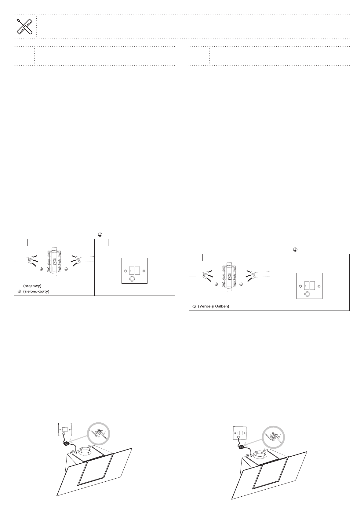
Urządzenie jest dostarczane z 3-żyłowym przewodem
zasilającym o następujących kolorach:
Brązowy = L (pod napięciem)
Niebieski = N (neutralny)
Zielono-żółty = E (uziemienie)
EUR UK
(niebieski)
N
L
N
L
N
L
FUSE ON
GNIAZDO DWUBIEGUNOWE Z
WYŁĄCZNIKIEM I BEZPIECZNIKIEM
UŻYĆ BEZPIECZNIKA 3A
Aby ograniczyć do minimum ryzyko związane z
użytkowaniem urządzenia elektrycznego, niezwykle ważne
jest, aby produkt został prawidłowo zamontowany oraz
aby użytkownik dokładnie zapoznał się z instrukcjami
dotyczącymi bezpieczeństwa i unikał nieprawidłowej obsługi
oraz związanych z tym zagrożeń. Należy zachować instrukcję
obsługi w celu wykorzystania w przyszłości i przekazania jej
kolejnym właścicielom. Po rozpakowaniu urządzenia upewnić
się, że nie jest ono uszkodzone. W przypadku wątpliwości
nie używać urządzenia i skontaktować się z działem obsługi
klienta. Więcej szczegółowych informacji znajduje się na
końcu części Czyszczenie i konserwacja.
Po określeniu punktu połączenia elektrycznego i
poprowadzeniu przewodu zasilania należy upewnić
się, że nadmiar przewodu jest zabezpieczony w taki
sposób, aby uniemożliwić mu upadek na obudowę silnika
i uszkodzenie urządzenia.
RO Conectarea la alimentarea
electrică
Instalarea trebuie să fie realizată în totalitate de o
persoană competentă sau de un electrician calificat.
Înainte de conectarea la rețeaua electrică, asigurați-vă
că tensiunea rețelei corespunde cu tensiunea de pe
plăcuța de identificare.
Conexiune directă
Aparatul trebuie conectat direct la rețea cu ajutorul
unui disjunctor omnipolar cu o deschidere minimă între
contacte de 3 mm.
Instalatorul trebuie să se asigure că a realizat corect
legăturile electrice și că a respectat schema electrică.
Cablul nu trebuie să fie îndoit sau comprimat.
Fișa de rețea și cablul de alimentare trebuie verificate în
mod regulat, pentru a identifica eventualele deteriorări.
În cazul în care cablul de alimentare este deteriorat,
trebuie înlocuit cu un cablu special sau cu o instalație
puse la dispoziție de producător sau agentul de service.
AVERTISMENT: Acesta este un aparat Clasa I și
TREBUIE împământat.
Acest aparat este echipat cu un cablu de alimentare cu
3 fire, colorate după cum urmează:
Maro = L sau fază
Albastru = N sau nul
Verde și galben = E sau împământare
EUR UK
(Albastru)
(Maro)
N
L
N
L
N
L
FUSE ON
IEȘIRE CU ÎNTRERUPĂTOR
BIPOLAR CU SIGURANȚĂ
FOLOSIȚI O SIGURANȚĂ DE 3 A
Pentru a evita riscurile aferente utilizării unui echipament
electric, este important ca acest aparat să fie instalat
corect și să citiți cu atenție instrucțiunile de siguranță, ca
să evitați utilizarea greșită și pericolele. Păstrați această
broșură cu instrucțiuni pentru consultare ulterioară și
predați-o proprietarilor viitori. După despachetarea
aparatului, verificați să nu fie deteriorat. Dacă aveți
îndoieli, nu folosiți aparatul, ci contactați Serviciul clienți
- a se vedea sfârșitul secțiunii Îngrijire și Întreținere,
pentru detalii.
După stabilirea rutei și amplasării cablurilor electrice,
toate cablurile suplimentare trebuie asigurate astfel
încât să se împiedice căderea acestora în carcasa
motorului, deteriorând în acest fel aparatul.

10
EN Installation FR Installation
PL Montaż RO Instalare
06 EN IMPORTANT: To proceed with installation, the cooker hood must be connected to a power
supply. Ensure that the electrical installation is completed before proceeding with step 06.
FR IMPORTANT: pour procéder à l'installation, la hotte aspirante doit être connectée à une
alimentation. S'assurer que l'installation électrique est terminée avant de passer à l'étape06.
PL WAŻNE: Aby kontynuować instalację, należy podłączyć okap kuchenny do źródła zasilania.
Przed przejściem do kroku 06 należy się upewnić, że instalacja elektryczna została zakończona.
RO IMPORTANT: Pentru a începe instalarea, hota de bucătărie trebuie conectată la sursa de
alimentare. Asigurați-vă că instalația electrică este finalizată înainte de a trece la pasul 06.
EN When the hood ON/OFF icon is blinking at step E turn off the power at the isolation switch.
FR Quand l'icône de marche/arrêt de la hotte clignote à l'étapeE, couper l'alimentation au niveau
de l'interrupteur d'isolement.
PL Gdy ikona wł./wył. okapu miga w punkcie E, wyłączyć zasilanie za pomocą odłącznika.
RO Când pictograma pornire/oprire de pe hotă luminează intermitent la pasul E, opriți
alimentarea de la întrerupătorul de izolare.
EN > 4 seconds
FR >4secondes
PL >4 sekundy
RO > 4 secunde
EN > 30 seconds
FR >30secondes
PL >30 sekundy
RO > 30 secunde
D E

11
EN Installation FR Installation
PL Montaż RO Instalare
07
[05] x2
[05]
x2

12
EN Installation FR Installation
PL Montaż RO Instalare
08
09
AEN Only for ducted option.
FR Uniquement pour l'option avec conduit.
PL Tylko dla opcji kanałowej.
RO Doar pentru opțiunea cu tubulatură.
A
A

13
EN Installation FR Installation
PL Montaż RO Instalare
10
11
BEN Only for recirculation option.
FR Uniquement pour l'option de recyclage.
PL Tylko dla opcji recyrkulacyjnej.
RO Doar pentru opțiunea de recirculare.
B
A B
07] x2
[
0
7
]

14
EN Installation FR Installation
PL Montaż RO Instalare
12
13
B
A B
CARBFILT 50

15
EN Installation FR Installation
PL Montaż RO Instalare
14
15
BA
BA
EN Turn the power on at the isolation switch and the glass will retract automatically.
FR
Remettre l'alimentation au niveau de l'interrupteur d'isolement. La vitre se replie automatiquement.
PL Włączyć zasilanie za pomocą odłącznika — szyba cofnie się automatycznie.
RO Porniți alimentarea de la întrerupătorul de izolare și sticla se va retrage automat.
EN Stainless steel only.
FR Acier inoxydable uniquement.
PL Tylko stal nierdzewna.
RO Doar oțel inoxidabil.

16
EN Use FR Utilisation
PL Użytkowanie RO Utilizare
EN Before you start
WARNING: Read the instructions before using the appliance.
Switch on the appliance at the switched fused connection unit. The appliance is ready for use.
EN Functions & Settings
01 Control panel
To obtain the best results from your cooker hood it is recommended that you leave it switched on for a short time after
you have finished cooking.
Timer
Fan Boost Function and Speed Increase
Hood On/Off
LED Display
Fan Speed Reduction
Light On/Off
Movement Sensor
To Set Up For First Time Use
Once you have turned on the appliance at the switched fused connection unit, all the icons will start to blink white. The
hood is now in settings mode.
If you do not want to set up the hood at this stage it can be turned off by pressing the Hood On/Off Icon or
alternatively, it will switch off automatically after 30 seconds.
IMPORTANT: Once in settings mode, you can adjust the recirculation, lighting or sensor options in any order.
However, all actions must be completed within two minutes.
Setting the Ducted or Recirculation mode
Turn off the power first and within 30 seconds of turning on the mains power again, press the Timer Icon and the Timer
Icon will turn blue. The LED display will show the current Ducted or Recirculation mode.
Ducted mode the default setting to extract air to the outside.
Recirculation mode the setting to recirculate the air with carbon filters installed.
To change this option press either or to select the correct mode and then press Timer Icon to accept the change.
Setting the Lighting mode
Within 30 seconds of turning on the mains power, press the Light Icon and the Light Icon will turn blue. The LED
display will show the current lighting mode.
Ambient light enabled Default setting, all lights are enabled.
Ambient light disabled Optional, down lights only are enabled.
Cool light Default setting for all lights.
Warm light Optional setting for all lights.
To change these settings press or and press the Light Icon to accept the change.

17
EN Use FR Utilisation
PL Użytkowanie RO Utilizare
Setting the Movement Sensor
Within 30 seconds of turning on the mains power, press the Timer and Light Icons together for 2 seconds to adjust the
Movement Sensor. Repeat this process to alter the sensor setting if required. The LED display will show the selected mode.
Sensor enabled the display will flash for 5 seconds - default setting.
Sensor disabled the display will remain solid for 5 seconds.
Note: To change any of these settings at a later time, you must switch off the power at the mains outlet first. Wait a
few seconds, turn on the power again and adjust as required.
02 General Use
On/Off
1. Touch the Hood On/Off Icon and the glass panel of the cooker hood will open. The fan will turn on at speed 1 and
the light will come on at the last setting used. All icons will be white apart from the Light Icon which will be blue if
the light was already on.
2. Press the On/Off Icon again to turn off the cooker hood; the glass panel will close and the fan will switch off. The
light will also turn off automatically after 5 minutes. If you wish to leave the light on for an extended time, manually
switch on at the control panel.
Movement Sensor (if enabled)
You can switch on the cooker hood by passing your hand in front of the Movement Sensor. Note you cannot turn off the
cooker hood using the Movement Sensor, you must touch the Hood On/Off Icon instead.
Light On/Off
1. Touch the Light Icon to turn on the downlight and also the ambient light (if enabled).
2. To change the brightness of the downlight, touch and hold the Light Icon until the display shows the brightness
sequence. Remove your finger from the Light Icon when the desired brightness is achieved. The sequence runs from
L1 to L5 and back to L1 in steps. The selected brightness will flash for a few seconds and revert to the fan speed display.
Fan On/Off and Speed Reduction
1. If the fan motor is set at speeds 2, 3, 4, 5 or P, pressing the Fan Decrease Icon will reduce the speed by one level at a
time. If you press the Fan Decrease Icon for more than two seconds, the speed will drop to speed 1 from any other level.
2. If the fan motor is set at speed 1, pressing the Fan Decrease Icon will result in the motor switching off. However
the downlight will remain on (if enabled) and the display will show the current brightness level.
Boost Function and Speed Increase
If the fan motor is set at speeds 1, 2, 3, 4 or 5, pressing the Fan Increase Icon will increase the speed by one level at
a time. If you press the Fan Increase Icon for more than two seconds, the speed will increase to full power from any
level and the display will flash.
NOTE: Full power or Boost (P) only operates for five minutes maximum to conserve energy and the fan speed will
automatically drop to speed level 5 after this time.
Setting the Timer
1. When the fan motor is on and the Timer Icon is pressed the icon will flash blue and the display will show the
current fan speed.
2. The chosen speed level will remain in use for five minutes before dropping down to the next lowest speed. This speed
will remain in operation for two minutes before dropping down again. This will be repeated every two minutes unless
the speed is already at level 1 and then the fan will turn off. If the light is already on, this will also be turned off.
3. Pressing the Fan Decrease Icon or Fan Increase Icon during a current timer program will restart the countdown
process again with the first five minute cycle.
4. If the Timer Icon is pressed again during a current timer program, the cycle will be cancelled. The Timer Icon
will revert to white and the current fan speed will remain on indefinitely.
5. The maximum timer program cycle is 15 minutes: 5 minutes on P and then 2 minutes each on speed 5 down to speed 1.

18
EN Use FR Utilisation
PL Użytkowanie RO Utilizare
EN Controlling a GoodHome cooker hood remotely
IMPORTANT: This section is only applicable if you have purchased a GoodHome cooker hood.
The process for connecting the hood to the hob happens in three stages:
A) Configure the hob to transmit a radio frequency signal.
B) Configure the hood to receive this signal.
C) Lock the connectivity between the two appliances and complete the pairing process.
STAGE A
1. The induction hob must be switched on and showing the Home Screen display before proceeding.
0
Level
2. Touch the Main Menu key on the Home Screen to take you to the Settings menu. Touch the Connect icon to initiate the
pairing sequence and transmit a radio frequency signal from the hob. Do not touch the Hood connection button on the hob yet!
Settings Connect
How to connect to hood
Hood connection
IMPORTANT: To proceed with the connectivity operation, the hood must be switched off at the mains power switch.
Turn on the hood again and complete Stage B and C within two minutes. If connection is not successful, turn off the
hood again, wait for one minute and try again.
STAGE B
1. When the hood is first switched on, the control panel will blink white in Settings mode.
2. Touch the Fan Speed Increase icon and Fan Decrease icon together for two seconds on the hood control panel and both
icons will turn blue and the Automatic symbol “A” will appear in the display. The hood is configured to receive the signal.
Connect

19
EN Use FR Utilisation
PL Użytkowanie RO Utilizare
STAGE C
1. Now touch the Hood connection button on the hob and it will turn blue.
2. The hob will briefly show a connected message to indicate that the hob is now locked with the hood and the pairing
process is complete. The hood will also show the double “A” symbols in its control panel to indicate pairing is complete.
Connect
Connected to
GoodHome Hood
How to connect to hood
Hood connection
IMPORTANT: Once the hob and hood are paired and locked together you can now choose to use your GoodHome
appliances in three ways, Independent Control, Semi-Automatic Control and Automatic Control.
1. Independent Control - The Hood
connection button on the hob is OFF
and you can operate the hood’s fan
and extraction manually as required
independently of any settings on the hob.
Connect
How to connect to hood
Hood connection
2. Semi-Automatic Control - The Hood
connection button on the hob is ON
and you can control the hood’s fan and
extraction manually from the 360 Master
Control Key on the hob control panel.
Connect
How to connect to hood
Hood connection
3. Automatic Control - The Hood
connection button on the hob is ON and
the hob will control the hood’s fan and
extraction based upon the power levels in
use on the hob.
Connect
How to connect to hood
Hood connection

20
EN Use FR Utilisation
PL Użytkowanie RO Utilizare
NOTE: You do not need to complete the pairing process again if you switch off the Hood connection on the hob. The
link is stored in memory and will be reactivated once you have switched Hood connection back on.
NOTE: If you touch the Cooker Hood Control Panel key before connectivity is complete you will see this message on screen:
0
Level See your manual on how to
connect your cooker hood.
01 Controlling the cooker hood from your hob
Ensure the hob and hood connectivity has been completed and the Hood connection button is ON!
1. From the hob Home Screen, touch the Cooker Hood Icon to access the Cooker Hood Control Panel, and the icon
will turn blue.
0 0
Level Extraction
2. To control the extraction rate of the hood manually, rotate or touch the 360° Master Control Key from 0-5 and B for
boost. The Hood On/Off Icon on the hood will alternately flash blue and white. This is Semi-Automatic Control.
3
Extraction
3. To control the extraction rate of the hood automatically, touch the Auto Extraction Control icon on the hob. The
icon will turn green in colour and the hob will now automatically adjust the extraction rate of the hob according to
the power output of the hob. See the table below for details. This is Automatic Control.
55
Extraction Extraction
Other manuals for bamia GHAGML90
1
Table of contents
Languages:
Other GoodHome Ventilation Hood manuals

GoodHome
GoodHome bamia User manual

GoodHome
GoodHome bamia GHAGRO90 User manual

GoodHome
GoodHome bamia GHIH80 User manual

GoodHome
GoodHome GHAG60PLAS User manual

GoodHome
GoodHome bamia GHIH80 User manual

GoodHome
GoodHome bamia GHAGML90 User manual

GoodHome
GoodHome BAMIA GHAGRE90 User manual

GoodHome
GoodHome bamia User manual
Popular Ventilation Hood manuals by other brands

ROBLIN
ROBLIN Rubis user manual

Omega National Products
Omega National Products Baxter Arched installation instructions

Gorenje Plus
Gorenje Plus GHF6X user manual

Hoover
Hoover HCT60 Instruction on mounting and use

ROBLIN
ROBLIN Eclat/2 Murale 900 Instructions for use and installation

Electrolux
Electrolux EFT 520 user manual