4
I. SPECIFICATIONS
A. GENERAL
These Ceiling mount air handlers are available in
coolingcapacitiesof1.5,2,2.5and3nominaltonsof
cooling.Electricheat models are available incapaci-
ties of 5, 8 and 10 KW.
The units are designed to be installed in a horizontal
positionaboveadroppedceiling.Unitsarenottobe
installedoutsidethestructure.Thesemodelsare
designed for INDOOR USE ONLY.
Theinformationontheratingplateisincompliancewith
the FTC and DOE rating for single phase units in the
U.S.A..
IMPORTANT: The United States Environmental
ProtectionAgency(EPA)hasissuedvariousregu-
lationsregardingtheintroductionanddisposalof
refrigerants in this unit. Failure to follow these
regulations may harm the environment and can
lead to the imposition of substantial fines. Be-
cause these regulations may vary due to the
passageofnewlawswesuggestthatanyworkon
thisunitbedonebyacertifiedtechnician.Should
you have any questions please contact the local
office of the EPA.
B. MAJORCOMPONENTS
The unit includes a evaporator coil with flowrator as-
sembly, an indoor blower and all necessary internal
electricalwiring. The coolingsystem of these units is
factory-evacuated,chargedandperformancetested.
Refrigerant amount and type are indicated on rating
plate.
II. INSTALLATION
A. GENERAL
1a. INSTALLATION — This product is designed and
manufacturedtopermitinstallationinaccordance
with National Codes. It is the installer’s responsi-
bility to install the product in accordance with
NationalCodesand/orprevailinglocalcodesand
regulations.
1b. PRE-INSTALLATIONCHECK-POINTS —Beforeat-
tempting any installation, the following points
shouldbeconsidered:
Structuralstrengthofsupportingmembers
Clearancesandprovisionforservicing
Powersupplyandwiring
Air duct connections
Drain facilities and connections
2b. LOCATION - These units are designed to be in-
stalled in a horizontal position above a dropped
ceiling. The location of the unit should be based
onthoroughconsiderationofthePRE-INSTALLA-
TION CHECK POINTS.
B. INSTALLATION
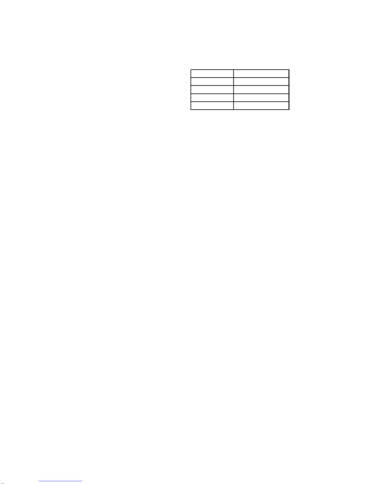
1. Before locating the unit on the dropped ceiling, make
sure that the strength of the ceiling and beams is
adequate at the point to support the weight involved.
Thisisveryimportantandinstallersresponsibility.The
followinglistshowsapproximate weight of unit.
MODEL WEIGHT (lb.)
AC18 59
AC24 59
AC30 69
AC36 79
2. The unit should be mounded on a horizontal position
above a dropped ceiling of adequate strength (see
Figure2)
3. Thelocationoftheunitshouldprovideproperaccessfor
inspectionandservicing.
C. DUCTING
Duct work should be fabricated by the installing con-
tractorinaccordancewithlocalcodes.Industrymanu-
als maybeusedasaguidewhensizinganddesigning
the duct system - such as NESCA (National Environ-
mental Systems Contractors Association, 1501 Wil-
sonBlvd.,Arlington,Virginia22209).
DO NOT, UNDER ANY CIRCUMSTANCES, CON-
NECTDUCTWORKTOANYOTHERHEATPRODUC-
INGDEVICESUCHASFIREPLACEINSERT,STOVE,
ETC.UNAUTHORIZEDUSEOFSUCHDEVICESMAY
RESULTINFIRE,CARBONMONOXIDEPOISONING,
EXPLOSION, PERSONAL INJURY OR PROPERTY
DAMAGE.
Thisunitshouldbeplacedas close to the space to be
airconditionedaspossible.Adequateclearancemust
bemaintainedasindicatedinSectionF“Clearances”.
Ducts should be run as directly as possible to supply
andreturnoutlets.Useofnon-flammableweatherproof
flexibleconnectorsonbothsupplyandreturnconnec-
tions at unit to reduce noise transmission is recom-
mended.
D. FILTERS
Filtersarenotprovidedwithunit,andmustbesupplied
andinstalledinthereturnairsystembytheinstaller.A
fieldinstalledfiltergrilleisrecommendedforeasyand
convenientaccesstothefilters,forperiodicinspection
andcleaning.Filtersmusthaveadequatefaceareafor
theratedairquantityoftheunit.Theminimumfiltersize
is 20" x 20" x 1".
E. CLEARANCES
These units are U.L. listed for installations with zero
clearancetocombustiblematerials,referenceshould
be made to the marking on the particular unit being
installed where specific information regarding clear-
ancesisprovided.Accessmustbeprovidedforservic-