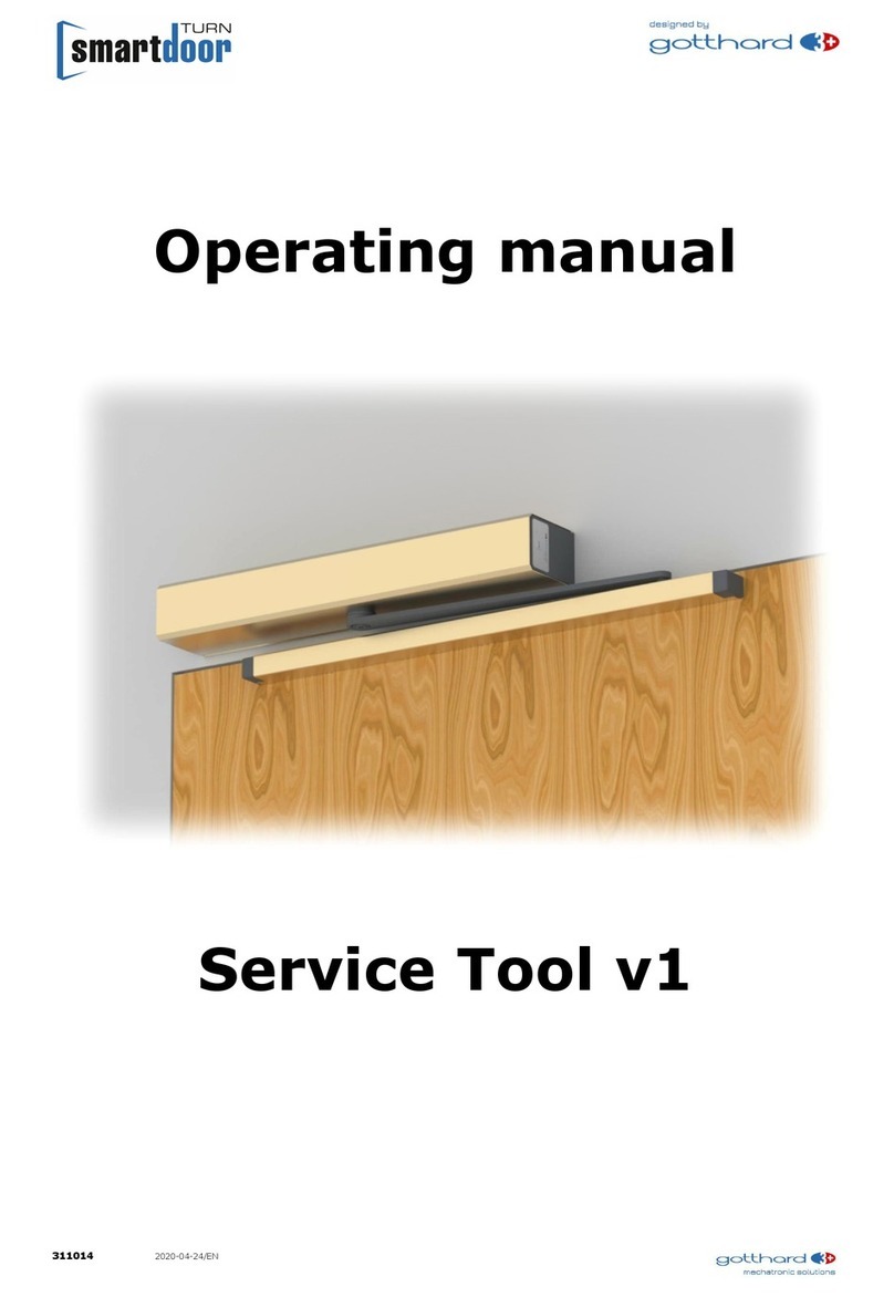
gotthard smartdoor TURN T100 User manual

301057 2021-10-26
Operating Instructions
Quick Guide
Swing Door Operator
smartdoor TURN T100
Language: English

smartdoor TURN T100 | Operating Instructions
2
Table of contents
1 GENERAL INFORMATION ......................................................................................... 5
1.1 PRODUCT IDENTIFICATION ................................................................................... 5
1.2 PRODUCT OVERVIEW ............................................................................................ 6
1.2.1 THE BASIC MODULE ............................................................................................. 6
1.2.2 THE LINKAGE..................................................................................................... 7
1.2.3 THE OPERATING ELEMENTS ..................................................................................... 7
1.2.4 THE SAFETY ELEMENTS ......................................................................................... 7
1.2.5 THE DRIVE MODULE ............................................................................................. 7
1.2.6 THE CONTROL MODULE ......................................................................................... 8
1.2.7 THE COMMUNICATION MODULE ................................................................................ 8
1.2.8 THE SMARTDOOR SERVICE TOOL .............................................................................. 9
1.2.9 THE SMARTDOOR APP .......................................................................................... 9
2 SAFETY ................................................................................................................. 10
2.1 SYMBOLS AND DISPLAY OF WARNINGS ................................................................ 10
2.2 STATE-OF-THE-ART AND APPLIED STANDARDS...................................................... 10
2.3 INTENDED USE .................................................................................................. 13
2.4 LIMITATION OF LIABILITY ................................................................................... 13
2.5 USER GROUP ..................................................................................................... 13
2.6 RISK ................................................................................................................. 13
2.7 MISUSE ............................................................................................................. 13
3 PRODUCT DESCRIPTION ....................................................................................... 15
3.1 TERMS .............................................................................................................. 15
3.2 SWING DOOR TERMS .......................................................................................... 16
3.3 LINKAGE TYPES ................................................................................................. 17
3.4 HOLDING VARIANTS ........................................................................................... 20
3.4.1 DOOR HANDLE WITH LATCH (WITH AND WITHOUT LOCK) ................................................ 20
3.4.2 DOOR HANDLE WITH BLOCKED LATCH (WITH AND WITHOUT LOCK) ..................................... 20
3.4.3 DOOR HANDLE WITH LATCH AND ELECTRIC DOOR OPENER ............................................... 21
4 ASSEMBLY ............................................................................................................. 22
4.1 SAFETY DURING ASSEMBLY: ............................................................................... 22
4.2 MECHANICAL INSTALLATION ............................................................................... 22
4.2.1 MOUNTING PLATE ............................................................................................. 23
4.2.2 ADAPTER PLATE ................................................................................................ 24
4.2.3 ASSEMBLY LINKAGE ........................................................................................... 24
4.2.4 LINKAGE DISASSEMBLY ....................................................................................... 25
4.3 ELECTRIC INSTALLATION .................................................................................... 26
4.3.1 CONNECTION AC VERSION ................................................................................... 26
4.3.2 CONNECTION DC VERSION .................................................................................. 26
4.4 COMMISSIONING VIA AUTO-LEARNING FUNCTION ................................................. 27
4.4.1 FUNCTIONAL TEST (COMMISSIONING PUSH&GO) ......................................................... 27
4.4.2 FUNCTIONAL TEST (AFTER INSTALLATION) ................................................................. 27
4.4.3 HOLDING FORCE FUNCTIONAL TEST IN THE CASE OF CURRENT INTERRUPTION ........................ 27
4.4.4 FUNCTION TEST (START AFTER CURRENT INTERRUPTION) ................................................ 27
4.5 COMMISSIONING OPERATING ELEMENTS .............................................................. 28
4.5.1 BLUETOOTH OPERATING ELEMENTS ......................................................................... 28
4.5.1.1 ADDITION OF BLUETOOTH OPERATING ELEMENTS ...................................................... 28
4.5.1.2 DELETING BLUETOOTH OPERATING ELEMENTS .......................................................... 29
4.5.1.3 COMMISSIONING OF SMARTDOOR BLUETOOTH PUSH BUTTON ........................................ 29
4.5.1.4 COMMISSIONING OF SMARTDOOR BLUETOOTH MODULE (WITH PUSH BUTTON) .................... 30
4.5.1.5 ADDITION OF SMARTPHONE ............................................................................... 31

smartdoor TURN T100 | Operating Instructions
3
4.5.2 WIRED OPERATING ELEMENTS ............................................................................... 31
4.5.2.1 CONNECTION OF EXTERNAL CONTACTS .................................................................. 31
4.5.2.2 WIRED OPENING PULSES .................................................................................. 31
4.5.2.3 COMMISSIONING WIRED PUSH BUTTON .................................................................. 31
4.5.2.4 COMMISSIONING WIRED RADAR .......................................................................... 32
4.6 COMMISSIONING SAFETY ELEMENTS .................................................................... 32
4.6.1 COMMISSIONING SIO AND SIS PRESENCE SENSORS .................................................... 33
4.6.1.1 CONNECTION SIO / SIS .................................................................................. 33
4.6.1.2 TEST SIGNAL TEST ........................................................................................ 33
4.6.2 COMMISSIONING ELECTRIC DOOR OPENER (COM, NO AND NC) ....................................... 34
4.6.3 COMMISSIONING MOTOR LOCK (COM, NO AND NC AND MORE) ....................................... 35
4.6.4 COMMISSIONING DAY/NIGHT SWITCH-OVER .............................................................. 36
4.6.5 COMMISSIONING CLOSING SEQUENCE CONTROL (WIRED) ............................................... 37
4.6.5.1 LOCKING THE STATIONARY LEAF: ......................................................................... 38
4.6.5.2 INTERLOCKING THE TRAFFIC LEAF: ....................................................................... 39
4.6.5.3 OPENING THE TRAFFIC LEAF ONLY: ....................................................................... 39
4.6.5.4 SHOT BOLT OF STATIONARY LEAF: ....................................................................... 39
4.6.6 COMMISSIONING AIRLOCK DOOR (WIRED) ................................................................. 40
4.6.6.1 MUTUAL INTERLOCKING: .................................................................................. 41
4.7 ESCAPE DOORS ................................................................................................. 42
4.8 FIRE DOORS ...................................................................................................... 42
5 FUNCTIONS ........................................................................................................... 43
5.1 AUTOMATIC SWITCH-ON FUNCTION AFTER POWER FAILURE ................................... 43
5.2 AUTOMATIC TROUBLESHOOTING FUNCTION.......................................................... 43
5.3 AUTO-LEARNING FUNCTION ................................................................................ 44
5.3.1 PREREQUISITES ............................................................................................... 44
5.3.2 IMPLEMENTATION OF THE AUTO-LEARNING FUNCTION (WITH PROG KEY) ............................ 45
5.4 LOW-ENERGY MODE ........................................................................................... 46
5.5 FUNCTIONS OF INPUTS AND OUTPUTS ................................................................. 47
5.5.1 SIO: SAFETY SENSOR OPENING ............................................................................ 47
5.5.2 SIS: SAFETY SENSOR CLOSING............................................................................. 47
5.5.3 OPENING PULSE (DAY+NIGHT) ............................................................................. 47
5.5.4 OPENING PULSE (DAY+NIGHT) + LOCK FEEDBACK ...................................................... 47
5.5.5 OPENING PULSE (DAY) ....................................................................................... 47
5.5.6 DAY/NIGHT SWITCH-OVER ................................................................................... 48
5.5.7 LOCK FEEDBACK ............................................................................................... 48
5.5.8 MODE SWITCH-OVER ........................................................................................ 48
5.6 CLOSING SEQUENCE CONTROL FUNCTION ............................................................ 48
5.7 AIRLOCK DOOR FUNCTION .................................................................................. 48
6 OPERATING MODE ................................................................................................ 49
6.1 AUTOMATIC OPERATING MODE (LED: GREEN) ....................................................... 49
6.2 OPERATING MODE - CONTINUOUSLY OPEN (LED: FLASHING GREEN) ....................... 50
6.3 OPERATING STATUS INITIALISATION (LED: FLASHING ORANGE) ............................. 50
6.4 AUTO-LEARNING OPERATING STATUS (LED: FLASHING RED/ORANGE) ..................... 51
6.5 SYSTEM ERROR OPERATING STATUS (LED: FLASHING RED) .................................... 51
7 OPERATION .......................................................................................................... 52
7.1 MAIN SWITCH .................................................................................................... 52
7.2 SETTING THE HOLD-OPEN TIME ........................................................................... 52
7.2.1 PROCESS ....................................................................................................... 52
7.3 MANUAL RESET OF AN ERROR ............................................................................. 53
7.3.1 PROCESS ....................................................................................................... 53
7.4 SWITCHING OVER THE OPERATING MODE............................................................. 53
7.4.1 SWITCH-OVER OF THE OPERATING MODE .................................................................. 53
7.5 SMARTDOOR APP ............................................................................................... 54
7.5.1 SYMBOLS ....................................................................................................... 54

smartdoor TURN T100 | Operating Instructions
4
7.5.2 MAIN MENU - MY DOORS ..................................................................................... 55
7.5.3 CONNECT NEW DOOR OPERATOR IN THE APP .............................................................. 55
7.5.4 PASSWORD FOR RELEASE OF A SMARTPHONE .............................................................. 55
7.5.5 DOOR CONTROL ............................................................................................... 56
7.5.6 USER MANUAL / FAQ ......................................................................................... 57
8 SERVICE ................................................................................................................ 58
8.1 CARE / OPERATOR CHECKS ................................................................................. 58
8.1.1 SWITCH OFF ................................................................................................... 58
8.1.2 CHECKS ........................................................................................................ 58
8.1.3 CARE ............................................................................................................ 58
8.2 MAINTENANCE / INSPECTION BY TRAINED SPECIALIST PERSONNEL ........................ 58
9 TROUBLESHOOTING .............................................................................................. 59
9.1 RESET ............................................................................................................... 59
9.1.1 PROCESS ....................................................................................................... 59
10 TECHNICAL DATA ............................................................................................... 60
10.1 AREA OF USE AND OPENING TIMES IN LOW-ENERGY OPERATION ............................ 60
11 APPENDIX .......................................................................................................... 62
11.1 CONNECTING TERMINALS ................................................................................... 62
11.2 ASSIGNMENT OF FUNCTION TO INPUTS AND OUTPUTS .......................................... 63
11.3 DISPLAY LED AND SYSTEM ERROR ....................................................................... 64
11.3.1 COMMUNICATION MODULE ................................................................................... 64
11.3.2 CONTROL MODULE ............................................................................................ 64
11.4 CONSTRUCTION PLANNER TEMPLATE – OBJECT OVERVIEW ..................................... 66
11.5 CONSTRUCTION PLANNER TEMPLATE – ELECTRICAL DIAGRAM ................................ 67
11.6 ELECTRICAL DIAGRAMS ...................................................................................... 68
11.6.1 EXAMPLE ELECTRIC DOOR OPENER (MASTER) .............................................................. 68
11.6.2 EXAMPLE ELECTRIC DOOR OPENER (MASTER WITH RELEASE) V1 ........................................ 69
11.6.3 EXAMPLE ELECTRIC DOOR OPENER (SLAVE) ................................................................ 70
11.6.4 EXAMPLE CONVERSION OF ELECTRIC DOOR OPENER WITH INTERCOM SYSTEM (DC) ................. 71
11.6.5 EXAMPLE MOTOR LOCK (MASTER-MASTER)................................................................. 72
11.6.6 EXAMPLE MOTOR LOCK (MASTER-SLAVE) ................................................................... 73
11.7 PUSH BUTTON TEMPLATE .................................................................................... 74
11.8 AUTO-LEARNING FUNCTION ................................................................................ 75

smartdoor TURN T100 | Operating Instructions
5
1 General information
1.1 Product identification
For precise identification the type plate attached to the control module is marked with the
following details:
Company name: Gotthard 3 Mechatronic Solutions AG
Gotthardstrasse 3
CH – 5630 Muri (AG)
Type: smartdoor TURN T100
Serial number: e.g. 0100-01-01-01-20-0000-0535
Reference number: 301010a (AC-version)
301011 (DC-version)
Year of manufacture: e.g. 2020
Mains connection: e.g. 100-240 V, 50/60 Hz
Power consumption: 41 W
Rated load: 30 Nm
Admissible temperature range: -15 °C to +50 °C
Classified according to DIN 18650-1:
* Self-closing in combination with a battery
Installation firm: (place holder for installation firm sticker)
Photographic example:
Figure 1: Product identification
1 2 3 4 5 6 7 8
1
2
1
2*
2.3 0
2

smartdoor TURN T100 | Operating Instructions
6
1.2 Product overview
Figure 2: Product overview
1.2.1 The basic module
The new EN 16005 standard defines the LOW-ENERGY operating mode and allows a door
operator to operate without safety elements without danger of injury. The smartdoor TURN
targets precisely this application. With its Auto-Learning function it automatically calculates the
necessary door parameters and makes easy work of commissioning. No safety elements are
required.
Figure 3: smartdoor TURN T100 basic module

smartdoor TURN T100 | Operating Instructions
7
1.2.2 The linkage
The smartdoor TURN can be fitted with the following linkage types:
Sliding linkage
Scissor linkage
The linkage types and their uses are described in chapter 3.3 Linkage types.
1.2.3 The operating elements
The smartdoor TURN can be fitted with the following elements:
smartdoor Bluetooth button which opens the smartdoor TURN and can switch between the
operating modes
Standard switch, which opens the smartdoor TURN or can switch between the operating
modes with the smartdoor Bluetooth module
smartdoor APP which can open the smartdoor TURN, switch between the operating modes
and change parameters
Wired standard switch which can open the smartdoor TURN
Wired radar which can open the smartdoor TURN
A separate function can be assigned to each button e.g. as opening contact (Day + Night),
opening contact (Day), or mode switch
Figure 4: Operating element examples
If there is an additional switch for disabled persons to activate the drive, a pictogram needs to
be applied to the button in accordance with EN 16005 Appendix D - picture D.1.
1.2.4 The safety elements
If you want to connect safety elements then the smartdoor TURN offers as standard a
connection strip for all standard safety elements.
The smartdoor TURN can be fitted with the following safety elements:
Presence sensors which control the swing range of the door in the opening direction (SIO)
Presence sensors which control the swing range of the door in the closing direction (SIS)
All standard motor locks and electric door openers (working current, static current)
Key switches, rotary switches or timers, to switch between day and night mode
Figure 5: Examples of safety elements
1.2.5 The drive module
This 1.7 kg, extremely compact power pack can supply a drive-side torque of over 30 Nm and is
practically silent. So that a driven door can also be actuated easily by hand (even without
electricity), its internal efficiency on both sides has been corresponding optimised. The sensor
system, integrated into the gearbox, allows a rapid and optimum reaction of the control system
to external influences. (detection of obstacles, wind pressure etc.)

smartdoor TURN T100 | Operating Instructions
8
Figure 6: Drive module
In the +/-15° range a mechanical reset torque is generated internally such that the door can be
held in the closed position without motor power. Thus, in the currentless state the door behaves
like a self-closing drawer.
The closing torque is symmetrically present in both directions of rotation. For this reason, a
swing door is held mechanically in the middle position, even in the currentless state.
1.2.6 The control module
The control module incorporates the control system, the connecting terminals and the power
supply.
Figure 7: Control module
The control module automatically learns (Auto-Learning) the correct direction of rotation and the
closing characteristic and saves this with system-related standard and limit values.
All possible connection options and the entire kinematic (lever systems, mass of the door leaf,
limit positions etc.) are detected and tested by the control module before each door opening.
1.2.7 The communication module
The smartdoor TURN has a communication module, which permits a switch-over of the
operating mode and communication with other devices. The communication module allows rapid
switching from Automatic mode to Continuously Open and back. An existing error can also be
manually acknowledged and the hold-open time set.
Figure 8: Communication module
More operating modes can be activated as required with the Service Tool.
The communication module is responsible for the communication with the smartdoor Bluetooth
button, Bluetooth modules, smartdoor APP and the Service Tool.

smartdoor TURN T100 | Operating Instructions
9
1.2.8 The smartdoor Service Tool
The smartdoor Service Tool can be used by the service technician on a Windows Notebook to
carry out a wide range of adjustments after mechanical installation. This includes the following:
Setting the parameters
Activation of Bluetooth devices
Saving and loading of parameter recipes
Auto-Learning
Managing and loading firmware
Status overview for controlled commissioning of external equipment
The Service Tool is only for trained specialist personnel. A detailed description of the smartdoor
Service Tool is provided in a separate handbook.
Figure 9: smartdoor Service Tool
1.2.9 The smartdoor APP
The smartdoor TURN can be operated and adjusted using the smartdoor APP.
A detailed description of the smartdoor APP can be found in chapter 7.5 smartdoor APP .
Figure 10: smartdoor APP

smartdoor TURN T100 | Operating Instructions
10
2 Safety
2.1 Symbols and display of warnings
Various symbols are used in these operating instructions for easier understanding:
NOTICE
Tips and information, which help you work correctly and efficiently.
CAUTION
Important note, when materials are damaged or the function can be affected.
WARNING
Important note, when materials are damaged or the function can be affected.
2.2 State-of-the-art and applied standards
The system complies with the state-of-the-art and accredited safety technology rules. It has
been developed, constructed and produced in compliance with the following standards:
Machinery Directive 2006/42/EC
Household and similar electrical appliances. Safety. EN 60335-1
Particular requirements for drives for gates, doors and windows EN 60335-2-103 (where
applicable)
Power operated pedestrian doorsets. Safety in use. Requirements and test methods. EN
16005.
Doors, gates and windows - Product standard, performance characteristics - Fire and / or
smoke protection properties EN 16034.
Safety-related parts of control systems EN ISO 13849
13849-1:2016 (General design principles), category 2 PL c
13849-2:2016 (Validation)
Electromagnetic compatibility (EMC) EN61000
Part 6-2: Generic standards – Immunity for industrial environments
Part 6-3: Generic standards – Emission standard for residential, commercial and light-
industrial environments
NOTICE
Partly completed machinery in the sense of the EC directive 2006/42/EC is only
designed to be installed in or combined with other machinery or in other partly

smartdoor TURN T100 | Operating Instructions
11
completed machinery or systems to form a machine in the sense of the above
directive.
WARNING
This product may not be operated until it has been determined that the whole
machine / system in which it has been installed, corresponds to the provisions of the
above EC directive.
In the event of any alteration of the product without the manufacturer's approval,
this declaration loses its validity.
NOTICE
The installer and operator must jointly carry out a risk assessment during the
planning of the system.

smartdoor TURN T100 | Operating Instructions
12
Encoding systems for automatic doors (DIN 18650)
1 – swing door operator
2 – Sliding door operator
3 – Swing/sliding door operator
4 – Folding door operator
5 – Revolving door drive
Drive type 1
1 – 200,000 test cycles at min. 1200 cycles/24 h
2 – 500,000 test cycles at min. 2400 cycles/24 h
3 – 1,000,000 test cycles at min. 4000 cycles/24 h
Durability of the drive 2
1 – Swing door
2 – Sliding door
3 – Swing/sliding door
4 – Folding door
5 – Revolving door
Door leaf type 3
0 – Not suitable as fire door
1 – Suitable as smoke-protection door
2* – Suitable as fire door
3 – Suitable as fire door & smoke-protection door
Suitability as fire door 4
1 – Force limit
2 – Connection for external safety systems
3 – Low energy
Safety devices on the drive 5
0 – No particular requirements
1 – In escape routes with a break-out fitting
2 – In escape routes without a break-out fitting
3 – For self-closing fire doors with break-out fitting
4 – For self-closing fire doors without a break-out
fitting
Special requirements of
drive/functions and
installation
6
0 – No safety devices
1 – With adequately dimensioned safety distances
2 – With protection against crushing, shearing and
trapping of fingers
3 – With built-in break-out fitting unit
4 – With presence sensor
Safety on the automatic
door system
7
1 – No specifications
2 – from -15 °C to +50 °C
3 – from -15 °C to +75 °C
4 – Temperature range in accordance with the
manufacturer's details
Ambient temperatures 8
* Self-closing in combination with a battery
Table 1: Encoding systems for automatic doors
Nos. 1, 2, 5, 6, 8 relate to the drives.
Nos. 3, 4, 7 relate to the complete door systems

smartdoor TURN T100 | Operating Instructions
13
2.3 Intended use
The smartdoor TURN T100 is an electromechanical swing door operator and is designed
exclusively for opening and closing swing doors for standard use in public and private dry
interiors and standard door heights.
Any other use is considered as improper use. The manufacturer is not liable for damage
resulting from improper use; the risk in this case lies entirely with the operator.
The smartdoor TURN T100 may be used on escape and rescue routes and on fire doors.
Intended use of equipment also includes compliance with the manufacturer's operating
instructions and regular care and maintenance.
2.4 Limitation of liability
Manipulation or modification of the parameters of the automatic door, unless performed by an
authorised service technician, exempts the manufacturer from liability for any resulting damage.
Modifications of the parameters may only be carried out by qualified personnel.
Installation is at one's own risk and must take place in accordance with operating instructions.
The manufacturer accepts no responsibility for non-compliance.
Assembly, commissioning, inspection, maintenance and repair work on the system must be
conducted according to the check lists. The chapter on commissioning (See chapter 5.3 Auto-
Learning function) and the maintenance checklist (see inspection book) may be helpful here.
Children may not clean, play with or use the product.
2.5 User group
The swing door operator can be used by children from 8 years and above, elderly and frail users
and persons with disabilities or with lack of experience and knowledge when these are
supervised or have been instructed in relation to the safe use of the appliances and understand
the resulting dangers.
Otherwise, the swing door operator should only be used when the risk assessment for the user
indicates a low risk.
2.6 Risk
There are risks of shearing and crushing from the various closing edges and the linkage on
automatic doors. To avoid this danger there should be no items in the opening area of the swing
door. The securing of crushing and shearing points on secondary closing edges must be
guaranteed by the door manufacturer.
The danger point on the secondary closing edge on each swing door (including manually
operated) is generally recognised by all users of a door. It cannot be influenced by the
manufacturer.
2.7 Misuse
Foreseeable misuse is any use other than as described in these operating instructions. This
includes:
mechanical or electrical bypassing
The use of other than original parts
Conversions, modifications and manipulations
Non-compliance with the instructions
NOTICE
The manufacturer stated in this report is only the manufacturer of a drive and not
the manufacturer of the final machinery.

smartdoor TURN T100 | Operating Instructions
14
The operator is responsible for the operation of automatic door systems and for
regular maintenance and safety inspections.
The "Operator checks" checklist can be helpful for this (see inspection book).

smartdoor TURN T100 | Operating Instructions
49
6 Operating mode
The smartdoor TURN knows the following operating modes:
Automatic: All operating and safety elements are active
Continuously open: The door remains open until the operating mode is changed
Initialisation: The door travels to the closed position and is locked
Auto-Learning: The door operator is in this operating status during the Auto-Learning process
System error: In the event of a system error the door operator switches to this operating
status
Trigger for MODE switch-over (trip command)
MODE button on the communication module
smartdoor Bluetooth push button
smartdoor Bluetooth module
smartdoor APP
Service Tool
A detailed description of the switch-over of the operating mode is given in chapter 7.4.1 Switch-
over of the operating mode.
6.1 Automatic operating mode (LED: green)
In this operating mode the door opens under all the trip commands listed below within the pre-
set opening time, remains open for the pre-set hold-open time and then closes within the preset
closing time.
Trigger for door opening (trip command)
Push&Go
smartdoor Bluetooth push button
smartdoor Bluetooth module
smartdoor APP
Input E1, E2, E3 or E4: Opening pulse (Day+Night)
Input E1, E2, E3 or E4: Opening pulse (Day + Night) + lock feedback
Input E1, E2, E3 or E4: Opening pulse (Day)
Functionality
Push&Go function, with wind gust detection
Low-energy
Closing sequence control for 2-leaf doors
Airlock: two or more successive, mutually interlocked doors
Automatic detection of safety elements
Adaptive opening speed (vandalism protection)
Situational obstacle detection when opening/closing
Unpowered closing torque in the closed position
Configuration and operation by smartdoor APP
Open
Operating mode selection
Hold-open time
Opening time (>3 seconds)
Closing time (>3 seconds)
Closing force (<67 N)
Angle correction OPEN position
Push&Go or gust
The door differentiates between a Push&Go pulse and wind gust.
The door has a sensitive Push&Go response so that children or elderly people can operate the
door in this way. You can adjust the sensitivity of the Push&Go pulse via the Service Tool.

smartdoor TURN T100 | Operating Instructions
50
A static wind pressure or wind gust is detected and does not cause the door to open. In the
holding version "Door handle with disabled latch" the door operator can, if required, ensure the
closed position with a current feed to the soft lock.
A static wind pressure or wind gust is also detected at closure and activates an automatic,
incremental increase of the closing force.
Adaptive opening speed
During opening, the door responds to pressure or pulling by the operator such that the door
operator surrenders the door control to the operator. As soon as the interaction by the operator
is interrupted, the door re-assumes control.
Obstacle detection
There is differentiation between obstacles when opening and obstacles when closing.
In the shear and crushing point area, the obstacle detection is more sensitive than in other
positions.
Behaviour - obstacle when opening
The behaviour in the case of an obstacle when opening can be set using the Service Tool.
Settings:
Behaviour in the case of an obstacle: stop or reverse
Number of attempts: 0-10
Behaviour - obstacle when closing
The behaviour in the case of an obstacle when closing can be set using the Service Tool.
Settings:
Behaviour in the case of an obstacle: stop or reverse
Extension of the hold-open time and maximum hold-open time
Number of attempts: 0-10
6.2 Operating mode - continuously open (LED: flashing green)
The door opens and remains open until the operating mode changes or the door is closed with a
Push&Go.
Trigger for door opening (trip command):
MODE button
smartdoor Bluetooth push button
smartdoor Bluetooth module
smartdoor APP
Functionality
Continuously open
6.3 Operating status initialisation (LED: flashing orange)
At initialisation, no operating mode is active. All operating and safety elements are deactivated.
Trigger
Power-ON
Automatic troubleshooting
Press and hold MODE button for 5 seconds

smartdoor TURN T100 | Operating Instructions
51
Functionality
The initialisation is indicated by 3 short beeps.
The drive then starts to move to its closed position.
Once reached, the drive acknowledges all impending errors and switches to the last selected
operating mode.
NOTICE
If the door operator was in Continuously Open MODE before a power failure, the
Continuously Open MODE is restored at Power-ON after successful initialisation.
6.4 Auto-Learning operating status (LED: flashing red/orange)
There is no active operating mode in the Auto-Learning function. All operating and safety
elements are deactivated.
Trigger
Service Tool
After Power ON press and hold down the PROG key for 5 seconds
Functionality
The Auto-Learning function is described in chapter 5.3 Auto-Learning function.
6.5 System error operating status (LED: flashing red)
In the case of a system error no operating mode is active. All operating and safety elements are
deactivated.
Trigger
None
Functionality
None

smartdoor TURN T100 | Operating Instructions
52
7 Operation
7.1 Main switch
In order to actuate the main switch the housing is removed. The main switch is located on the
opposite side of the MODE push button and is easily accessible on the top (see Figure 34: Main
switch).
With the main switch the connection voltage and all further auxiliary voltages within of the door
operator are switched off.
Figure 34: Main switch
WARNING
Only after switching off the main switch may an expert work with an open door
operator.
7.2 Setting the hold-open time
The hold-open time can be set using the MODE key of the communication module or the
smartdoor APP (see chapter 7.5.5 Door control).
The hold-open time must be set to between 5 and10 seconds.
7.2.1 Process
1 With the MODE button switch to the Continuously Open operating mode (see 7.4.1 Switch-
over of the operating mode)
2 Door opens and remains in the open position
3 Press MODE push button for 5 seconds until a long beep sounds
4 Wait for the desired hold-open time. You will hear a beep sounded at second intervals
5 Press and release MODE push button after the desired hold-open time
6 Door closes and the programming is concluded

smartdoor TURN T100 | Operating Instructions
53
7.3 Manual RESET of an error
In the event of an error the door remains in the current state, switches to system error
operating mode and indicates this with 10 beeps and a red flashing LED. In this state, all
operating and safety elements are deactivated.
If an error cannot be automatically remedied by the door operator (see chapter 5.2 Automatic
troubleshooting function), press and hold the MODE key (5 seconds) until a RESET is carried
out.
In this case the drive switches to initialisation MODE and starts to approach its closed position.
Once here, the drive acknowledges the error, switches to the last selected operating mode and
is once more ready for operation.
If the error remains, call an expert technician.
7.3.1 Process
Press MODE button for 5 seconds until 1 long beep sounds, then release the MODE button. This
carries out a RESET.
7.4 Switching over the operating mode
The smartdoor TURN knows the following operating modes:
Automatic: All operating and safety elements are active
Continuously open: The door remains open until the operating mode is changed
Initialisation: Operating status during initialisation
Auto-Learning: Operating status during the Auto-Learning function
System error: Operating status during which a system error applies
7.4.1 Switch-over of the operating mode
You can switch between the operating modes of the smartdoor TURN using the MODE button on
the communication module, the smartdoor Bluetooth push button, the smartdoor Bluetooth
module or the smartdoor APP. This means it is possible to switch quickly from Automatic mode
to Continuously Open and back.
Figure 35: Switch-over operating mode
More operating modes can be activated as required with the smartdoor APP. Switching over the
operating mode means that the released operating modes are actuated in turn. In this case the
LED lights up with the respectively selected operating mode.
The prevailing operating mode is always displayed. In this case the LED is lit in the
corresponding colour of the operating mode:
Automatic: green
Continuously open: flashing green
Initialisation: flashing orange (not available)
Auto-Learning: flashing red/orange (not available)
System error: flashing red (not available)
If the MODE button is actuated one more time the operating mode switches to the next state.
The LED is lit in the corresponding colour. The MODE button is actuated until the desired
operating mode is set.

smartdoor TURN T100 | Operating Instructions
54
7.5 smartdoor APP
With the smartdoor APP, the owner of smartdoor door operators can correspondingly adjust the
most important parameters according to their requirements.
In the process, the limit values are automatically adapted to the door configuration. It is
therefore for example not possible to set the opening or closing speed faster than the value
specified in LOW ENERGY.
NOTICE
No personal data or values are stored in the smartdoor APP
7.5.1 Symbols
The following symbols are used in the smartdoor APP:
Button:
Active
Inactive
Command: On Off
Menu:
Bluetooth
connection: Active Inactive
Editing: Active Inactive
Value display: adjustable Display only
Selection:
Clear:
Disabled:
Table 11: smartdoor APP symbols
Selection
6.0 6.0
Other manuals for smartdoor TURN T100
1
Table of contents
Other gotthard Door Opening System manuals
Popular Door Opening System manuals by other brands

Bortoluzzi
Bortoluzzi slider M50 manual

Lamp
Lamp SLUN-N quick start guide

Dominator
Dominator Select DSO-1 instruction manual

Erreka
Erreka VIVO-D103 Quick installation and programming guide

Assa Abloy
Assa Abloy Corbin Russwin DC3210 Series installation instructions

Von Duprin
Von Duprin 33A Series Service manual