2
ENGLISH
AUTOMATIC DOOR A100 COMPACT
1 DESCRIPTION
The FAAC series A100 COMPACT systems automatically activate,
manage and control the operation of single-leaf or two-leaf
sliding doors.
The FAAC series A100 COMPACT automated systems are supplied
completely assembled, wired and tested in the configuration
requested by the customer, using the appropriate order form, or
in kits to be assembled by the installation technician.
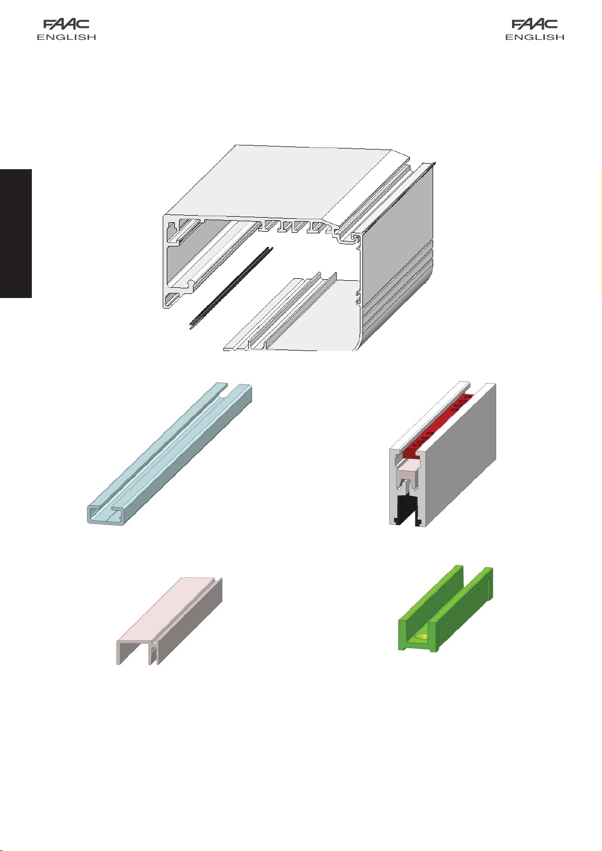
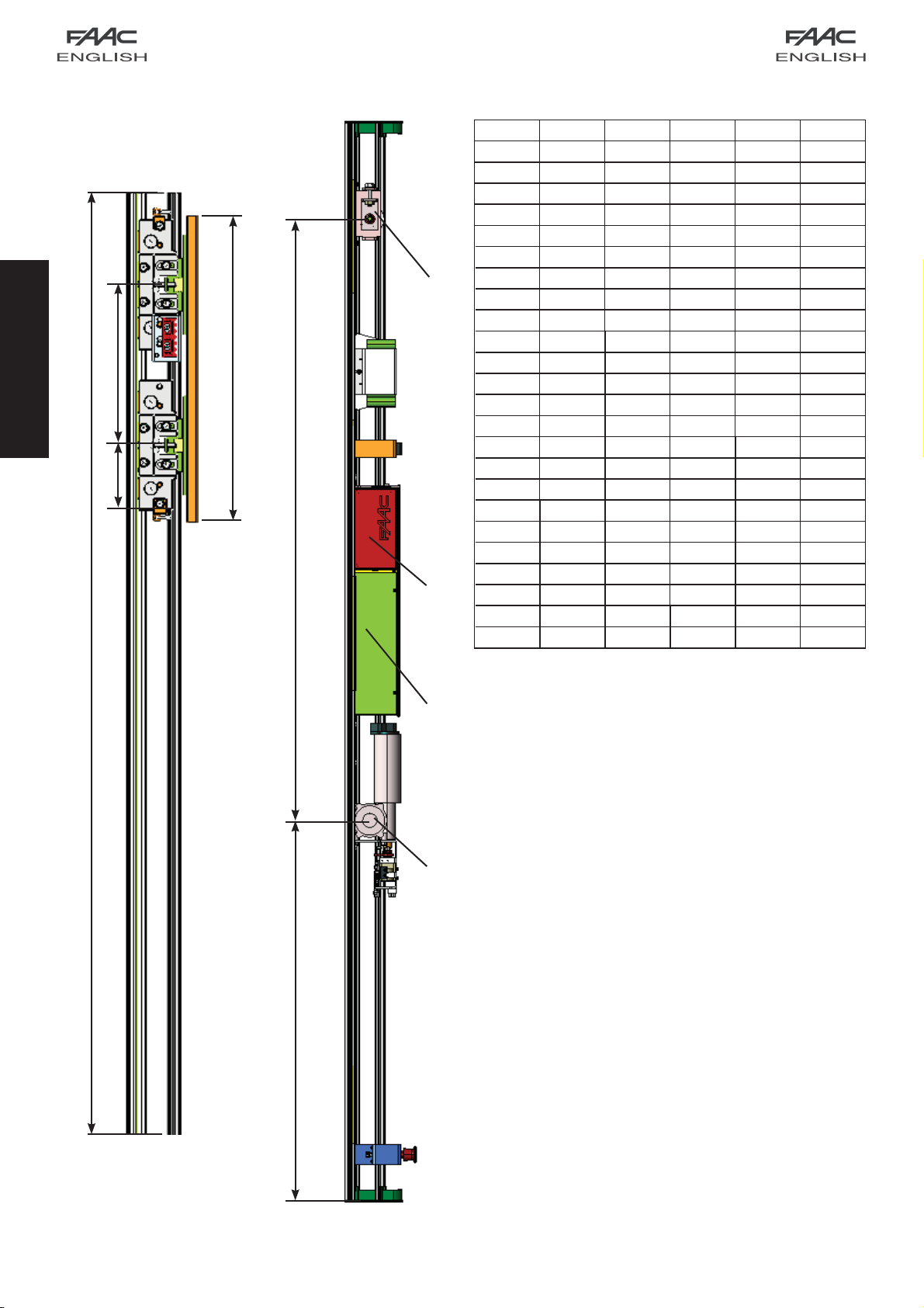
An automation cross beam (fig.1) consists of the following
parts:
Support profile (fig.1 ref.)
This is the profile used when the cross beam can be completely
secured to a load bearing structure.
Motor unit (fig. 1 ref.)
The DC motor has an encoder and a leaf locking system
(accessory).
Control unit (fig. 1 ref. )
When powered, the control unit with microprocessor, initialises
the door’s operational parameters.
Power feed unit (fig. 1 ref. )
The power feed unit, directly connected to the control unit,
supplies the voltage values required to correctly power the
automated system.
Leaf support carriages (fig.1 ref.)
The carriages have two wheels with ball bearings, one counter
thrust wheel in the top part, and a screw based system for
adjusting the height of the leaves.
Drive belt (fig. 1 ref. )
Transmission pulley unit (fig. 1 ref. )
1.1 ACCESSORIES SUPPLIED WITH THE CROSS BEAM
These parts are assembled on the cross beam.
Closing housings (fig. 1 ref. )
This is the aluminium profile enabling closure of the automated
system. The side panels (fig.1 ref.) completely close the
system.
Motor lock unit (fig. 1 ref. )
The motor lock unit guarantees mechanical locking of the door
while the leaves are closed. The motor lock unit can be used for
single and double leaves.
The motor lock unit is supplied with the internal release device
(Fig.1 ref.) used for emergency opening if needed. It is also
designed for installation of the external release (optional) if
required. The motor lock unit acts directly on the motor, locking
it mechanically.
Supervision of motor lock
It controls if the motor lock unit is operating correctly and verifies
if the door is actually closed. If necessary, the system is designed
for remotely activating an indicator light or buzzer/siren.
Emergency battery (fig. 1 ref. )
In the event of a mains power cut, the battery kit enables the
automated system to operate until its charge is exhausted. The
battery condition test is performed continuously by the control
unit.
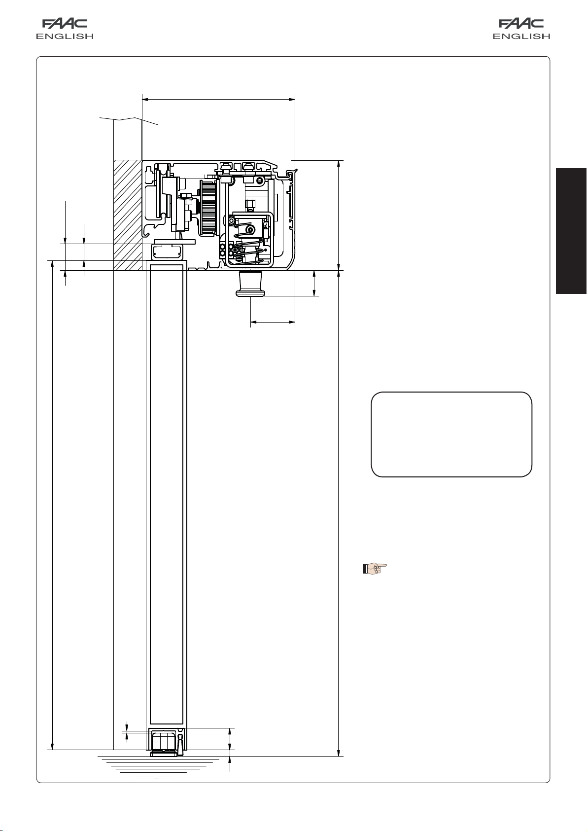
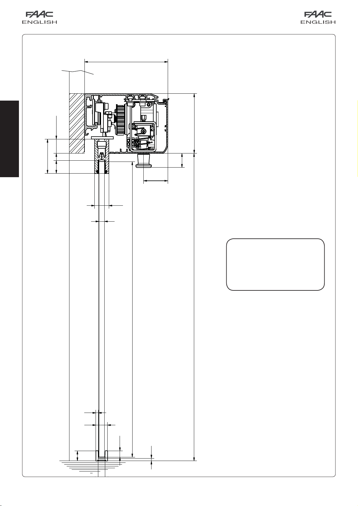
fig. 1