10
11. Safety Testing
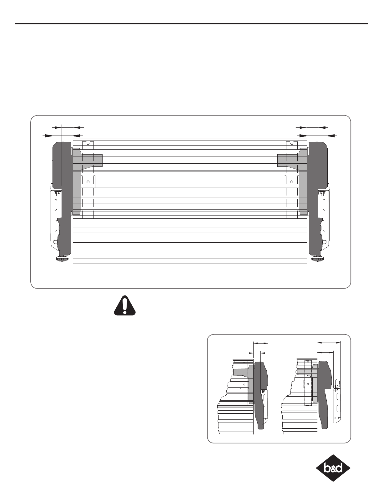
Test the Close Cycle
a. Press the OPERATE button to open the door.
b. If the door closes, press the OPERATE button to stop the door, then
press OPERATE again to open.
c. Place a piece of timber approximately 40mm high (or the openers
cardboard box) on the floor directly under the door.
d. Press the OPERATE button to close door.
e. The door should strike the object and re-open.
f. Remove the timber or cardboard box.
Testing the Open Cycle
a. Press the OPERATE button to close the door.
b. Press OPERATE again to open the door.
c. When the door reaches approximately half way, firmly grab the
door’s bottom rail - the door should stop.
If the door does not reverse readily when closing, or stop when
opening, put the door into manual by pulling down on the manual
release string to diesengage the motor and contact 1300 300 625
for support.
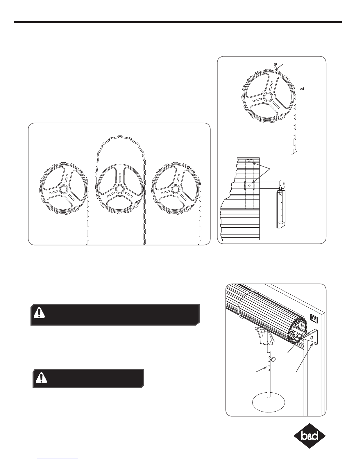
Test the Manual Door Operation
Periodically disengage the opener and manually operate the door.
The door must be smooth to operate by hand. The force required on
the bottom rail should not exceed 15 kg.
CAUTION: Take care when completing a
safety test. Failure to follow this warning
can result in serious personal injury and/or
property damage.
WARNING! If the door is closing and is unable
to re-open when obstructed, discontinue use.
Do not use a door with faulty obstruction sensing.
Wood 40mm
high or opener
cardboard box
To Recall Factory Set Force
a. Holding down the FORCE MARGIN SET button and
the LIMIT SET button for two seconds.
b. Release both buttons. The default setting should
now be recalled.
To Recalculate Force Margins
a. Press and hold the FORCE MARGIN SET Button for six
(6) seconds, the beeper will sound once.
b. The door will start to move and re-calculate
force margins. The door can move between the
open and close limit positions up to four (4) times
(depending on the position of the door and the
power up condition).
c. A single beep will be heard once the process is
complete.
d. Test the force again as per Testing Close Cycle and
Testing Open Cycle.
Adjusting Safety Obstruction Force
The Safety Obstruction Force is calculated automatically during
setup. Adjusting this is normally only necessitated by environmental
conditions such as windy or dusty areas, and areas with extreme
temperature changes.
To Increase Force Pressure
a. Hold down the FORCE MARGIN SET button.
b. While holding the FORCE MARGIN SET button, press the PLUS (+)
button. Each press will increases the force margin.
c. The OPEN LIMIT LED will flash each time the PLUS (+) button is
pressed to indicate an increase in force.
d. If the OPEN LIMIT LED flashes continuously when the PLUS (+) button
is being pressed, this indicates that the maximum force setting
has been reached.
e. Test the force again as per Testing Close Cycle and Testing Open
Cycle.
To Decrease Force Pressure
a. Hold down the FORCE MARGIN SET button.
b. While holding the FORCE MARGIN SET button, press the MINUS (-)
button. Each press will decrease the force margin.
c. The CLOSE LIMIT LED will flash each time the MINUS (-) button is
pressed to indicate a decrease in force.
d. If the CLOSE LIMIT LED flashes continuously when the MINUS (-)
button is being pressed, this indicates that the minimum force
setting has been reached.
e. Test the force again as per Testing Close Cycle and Testing Open
Cycle.
WARNING! If the door fails these tests,
put the opener into manual mode, only
operate the door by hand and call for
service.