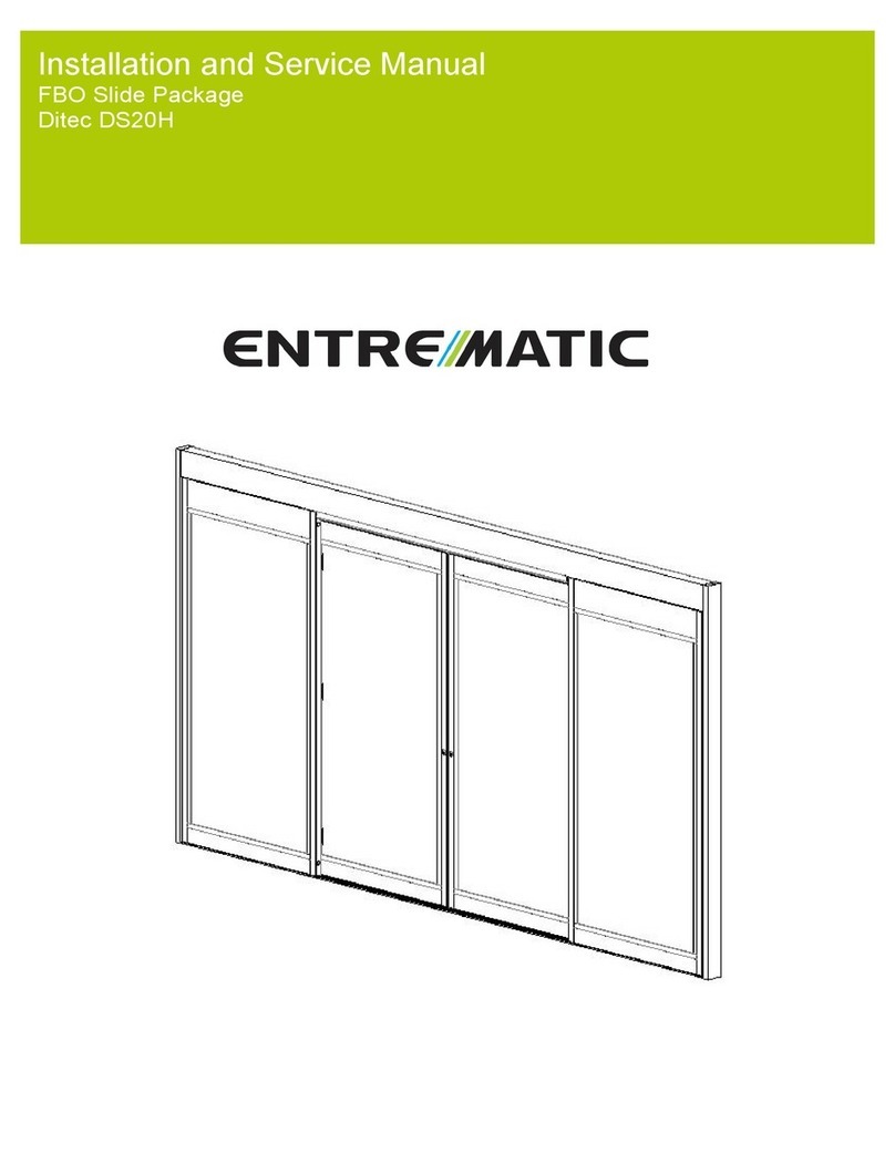
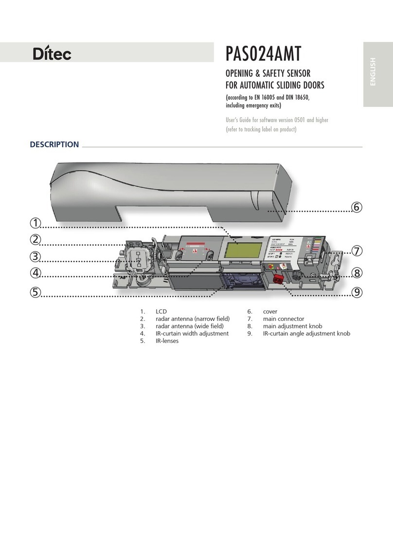
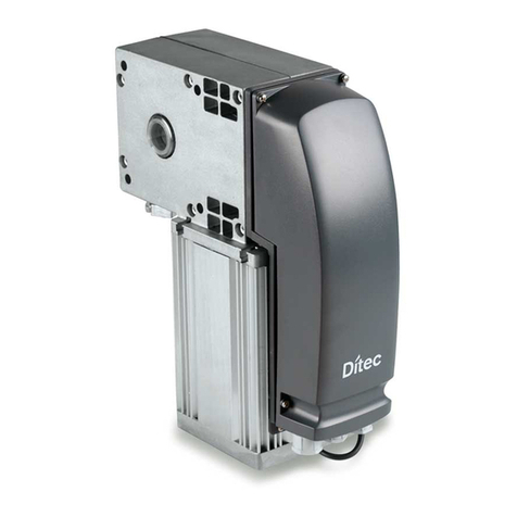
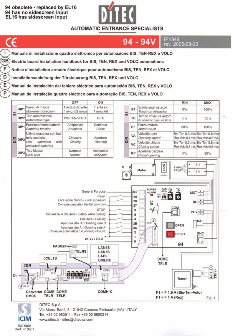
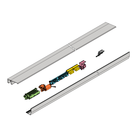
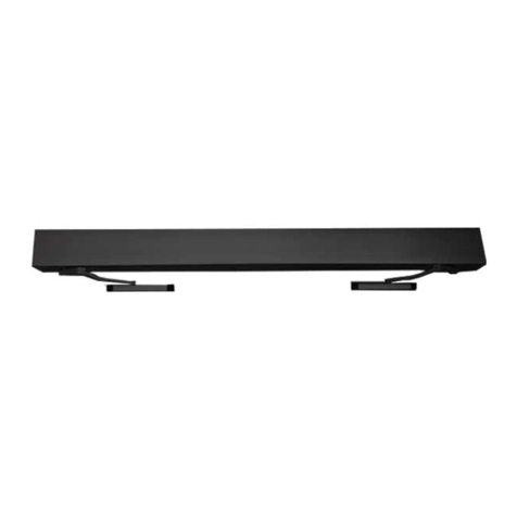
DITEC DAS200TRF User manual

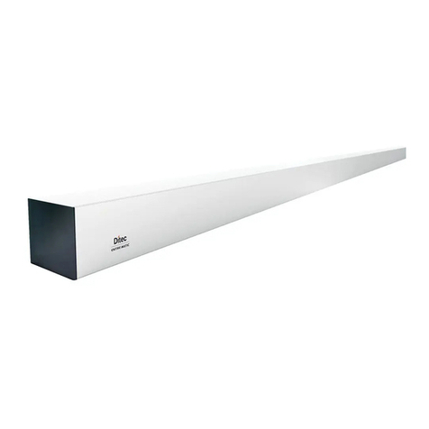
Ditec DAS200T
DAS200TRF-DAS200TRG
Sliding doors automation
(Original instructions)
Technical manual
IP2348EN • 2020-10-07
www.ditecentrematic.com

2
EN
IP2348EN
Contents
Legenda
i
This symbol indicates instructions or notes regarding safety, to which special atten-
tion must be paid.
This symbol indicates useful information for the correct functioning of the product.
Subject Page
1. General safety precautions 3
Declaration of incorporation of partly completed machinery 4
2. Technical data 5
3. Standard installation 6
4. Main components 7
5. Installing the automation 8
5.1 Installing / Removing the cover 8
5.2 Installation/removal of the cover if installed side presence sensor 8
5.3 Removing the front casing 9
5.4 Rear operator installation 9
5.5 Front operator installation 10
5.6 Installation examples using supplied wing anchoring brackets 10
5.7 Installing / Removing the cover 11
6. Example of box fastening 13
6.1 Examples with wing connection bracket DASTAC16 13
6.2 Example with wing connection bracket DAST30 14
6.3 Example with wing connection bracket DASTAC 14
7. Preparation of the glass door wing 16
7.1 Installing and adjusting the door wings 17
7.2 Floor guide installation 20
7.3 Belt stop installation 20
7.4 Checking and adjusting the belt tension 21
7.5 Sensor positioning on the cover 21
7.6 External sensor cable fixing 21
8. Electrical connections 22
8.1 Standard electrical connections 23
8.2 Control panel commands 25
8.2.1 Commands 25
8.3 DAS902MP plus module (optional) 27
8.4 DAS902MP commands 28
9. Adjustment and selection of control functions 30
9.1 Display test 31
9.2 Status indication on the display 31
10. Start up 32
11. Parameters 35
11.1 Configuration parameters according to function 35
11.2 Main control board parameters 38
12. Example of connection 49
12.1 Combined opening and safety sensor + safety sensor on opening 49
12.2 Interconnection of operators 51
12.2.1 Interconnection cable 51
12.2.2 Hardware configuration for interconnection 51
12.2.3 Parameter configuration for interconnection 52
12.3 Operation mode selector (OMS) functionality 52
12.4 Synchronization 53
12.5 Interlock 53
13. Troubleshooting 55
13.1 Active error indication 56
14. Routine maintenance plan 60

3
EN
IP2348EN
1. General safety precautions
This assembly and installation manual is intended exclusively for the use of qualified personnel.
Installation, electrical connections and adjustments must be performed by qualified personnel, in
accordance with Good Working Methods and in compliance with the current regulations.
Read the instructions carefully before installing the product.
Incorrect installation could be dangerous.
The packaging materials (plastic, polystyrene, etc.) should not be discarded in the environment
or left within reach of children, as they are a potential source of danger.
Before installing the product, make sure it is in perfect condition.
Do not install the product in explosive areas and atmospheres: the presence of inflammable gas
or fumes represents a serious safety hazard.
Before installing the motorisation device, make all the necessary structural modifications to
create safety clearance and to guard or isolate all the crushing, shearing, trapping and general
hazardous areas.
Make sure the existing structure is up to standard in terms of strength and stability. The motori-
sation device manufacturer is not responsible for failure to observe Good Working Methods when
building the frames to be motorised, or for any deformations during use.
The safety devices (photocells, safety edges, emergency stops, etc.) must be installed taking into
account the applicable laws and directives, Good Working Methods, installation premises, system
operating logic and the forces developed by the motorised door or gate.
The safety devices must protect against crushing, cutting, trapping and general danger areas of
the motorised door or gate.
Display the signs required by law to identify hazardous areas.
Each installation must bear a visible indication of the data identifying the motorised door or gate.
When necessary, connect the motorised door or gate to an effective earthing system that complies
with the current safety standards.
During installation, maintenance and repair operations, cut off the power supply before
opening the cover to access the electrical parts.
The automation protection casing must be removed by qualified personnel only.
The electronic parts must be handled using earthed antistatic conductive arms. The manufac-
turer of the motorisation device declines all responsibility if component parts not compatible
with safe and correct operation are fitted.
Only use original spare parts when repairing or replacing products.
The installer must supply all information concerning the automatic, manual and emergency ope-
ration of the motorised door or gate, and must provide the user with the operating instructions.
Failure to respect the information given in this manual
may cause personal injury or damage to the device.
Keep these instructions for future reference
4
EN
IP2348EN
Declaration of incorporation of partly completed
machinery
We:
Entrematic Group AB
Lodjursgatan 10
SE-261 44 Landskrona
Sweden
declare under our responsibility that the following types of equipment:
Ditec DAS200T, Ditec DAS200TRF, Ditec DAS200TRG
comply with the following directives:
2014/30/EU Electromagnetic Compatibility Directive (EMCD)
2006/42/EC Machinery Directive (MD) for the following essential health and safety
requirements: 1.1.2, 1.2.1, 1.2.2, 1.2.3, 1.2.4.2, 1.2.6, 1.3.9, 1.4.3, 1.7.2, 1.7.4,
1.7.4.1, 1.7.4.2
2011/65/EU on the restriction of the use of certain hazardous substances in electrical
and electronic equipment (RoHS)
Technical documentation for safe integration supplied.
Harmonised European standards which have been applied:
EN 60335 -1:2012+A13:2017 EN ISO 13849 -1:2015 EN 61000 -6-2:2005
EN 60335-2-103:2015 EN 16005:2012/AC:2015 EN 61000 -6-3:2007+A1:2011
Other standards or technical specifications, which have been applied:
IEC 60335-1: 2010 ed.5 IEC 60335-2-103:2006+A1:2010 AutSchR: 1997
DIN 18650-1:2010 DIN 18650-2:2010
EC type examination or certificate issued by a notified or competent body (for full address please
contact Entrematic Group AB) concerning the equipment:
B 085479 013( Ditec DAS200T, Ditec DAS200TRG)
B 085479 012( Ditec DAS200TRF)
The production process aims to guarantee that the equipment complies with the technical
documentation.
The production process is regularly assessed by an independent body.
The equipment must not be put into service until the final door system installed has been
declared compliant with the Machinery Directive 2006/42/EC by the installer.
Person in charge of technical data sheet:
Entrematic Group AB
Lodjursgatan 10
SE-261 44 Landskrona
Sweden
Place Date Signature Position
Landskrona 2020-10-07 Matteo Fino Entrance Automation President
Matteo
Fi
no
o
o
o
o
o
o
o
o
no
o
no
o
o
o
o
no
o
o
o
no
o
o
o
no
no
no
no
n

5
EN
IP2348EN
2. Technical data
Ditec DAS200T
Ditec DAS200TRF Ditec DAS200TRG
Power supply 110V~ / 240V~
50/60Hz
110V~ / 240V~
50/60Hz
Power supply rated
power (PS) 150W 150W
Max Opening speed
(4 door wings) 1,6m/s 1,6m/s
Maximum load 120kg/wing( 1+1 wing)
80kg/wing ( 2+2 wings)
120kg/wing( 1+1 wing)
80kg/wing ( 2+2 wings)
Intermittence S3=100% S3=100%
Temperature
-20°C +50°C
-20°C +50°C
Degree of protection IP20
(FOR INTERNAL USE ONLY)
IP20
(FOR INTERNAL USE ONLY)
Control panel
(MCU/MCU-ER) 1DAS20HDQE 1DAS20RGQE
Accessories power
supply 24V 1A 24V 1A
Durability test 1.000.000 cycles 1.000.000 cycles
TYPE OF USE Ditec DAS200T Ditec DAS200TRF Ditec DAS200TRG
Sliding door automation
Escape route with rubber band
opening system
Escape route with redundant
system

1
32
A
5
4
4
6
EN
IP2348EN
3. Standard installation
Ref. Description
1Automation for sliding doors
2
3Combined opening and safe closing sensor
4Safe opening sensor
5Program selector
AConnect the power supply cable to a type-approved omnipolar switch with category III insulation and
a contact opening distance of at least 3mm.
The connections to the mains and low voltage wires must be made on an independent channel se-
parated from the connections to the command and safety devices (SELV= Safety Extra Low Voltage).

6
8
DAS200TRF DAS200TRF
9
17 17
14
16
713
1211
1016 15
7
EN
IP2348EN
4. Main components
i
NOTE: the given operating and performance features can only be guaranteed with the
use of DITEC accessories and safety devices.
Ref. Code Description
6 DASLOKSB Built-in manual release device (optional)
7- Mains power supply
8 1DAS20HAL 150W power supply unit (PS)
91DAS20HMR
1DAS20RGMR
DAS200T-DAS200TRF gearmotor
DAS200TRG gearmotor
10 1DAS20HDQE
1DAS20RGQE
DAS200T-DAS200TRF (MCU) control panel
DAS200TRG control panel (MCU-ER)
11 DAS902MP DAS902MP plus module (optional)
12 DAS901BAT1
DAS902BAT2
12V batteries (set parameter 43= 05)
24V batteries (the fuse in the cable harness is T10A)
13 DAS802B50 Drive belt
14
DAS802LOK
DAS802LOKA
DAS802LOKB
Standard lock. Locked with power - LD
Anti-panic lock. Locked without power - LDP
Bi-stable lock-LDB
15 - Belt transmission
16 - Mechanical stops
17 - Pulley for rubber band (DAS200TRF)

1
2
3
2
3
4
1T20
8
EN
IP2348EN
5. Installing the automation
5.1 Removing the cover
5.2 Removal of the cover if installed side presence sensor

HM= H-39
80
max 70
19
H
27 2030
6
12
KPAM45
9
x 2
8
7
5 6
6
T30 T20
WARNING: the fastening of the box to the
wall must be sufficient to sustain the door
wing weight.
WARNING: do not damage the wheel guide
during assembly. Clean the guide thorou-
ghly beforeinstalling the wings.
9
EN
IP2348EN
5.4 Rear operator installation
5.3 Removing the front casing
Unless otherwise specified, all measurements are
expressed in millimetres (mm).
The figure shows the
measurements for fastening the automation to the wall,
considering that the automation door wings are made
using profiles not manufactured by us.
If the door wings
are made with DITEC profiles in the ALU/PAM series: re-
fer to the measurements given in the relative manuals.
Drill a hole in the box using the reference line on the
back and fasten it with M6 Ø12 steel plugs or 6MA
screws (not supplied). Distribute the fixing points ap-
prox. every 400 mm. Make sure the box is positioned
evenly, with its back surface perpendicular to the floor
and not deformed lengthwise by the shape of the wall.
If the wall is not straight and smooth, iron plates must
be fixed to it and then the box in turn fixed to the plates.

x 2 12 13
T30 T20
50 1000 1000 1000
10
11
13
max 70
6
12
KPAM45
HM= H-39
max 70
KPAM45
80
19
H
27 2030
2995
After wings installation
10
EN
IP2348EN
5.6 Installation examples using supplied wing anchoring brackets
5.5 Front operator installation

11
EN
IP2348EN
5.7 Installing / Removing the cover
120
265
80
203027
22 48
20
ALU48
1
2
3
DAS40M8
DAS200T-DAS40M8-ALU48

500
CLICK
12
EN
IP2348EN
• Secure and unsecure the open cover as shown below.

13
EN
IP2348EN
6 Example of box fastening
6.1 Examples with wing connection bracket DASTAC16
120
265
80
203027
16
47
55
PAM16
120
265
80
203027
2248
43
AC1356
DASTAC16
DASTAC16
DAS200T-PAM16
DAS200T-AC1356

14
EN
IP2348EN
6.2 Example with wing connection bracket DAST30
6.3 Example with wing connection bracket DASTAC
120
265
80
180
2030
28
30
23
29
PAM30
120
265
80
203027
2546
43
AC4255
DAST30
DASTAC
DAS200T-AC4255
DAS200T-PAM30

15
EN
IP2348EN
120
265
80
203027
25
49
AC4870
DASTAC
DAS200T-AC4870

Ø10 Ø10 Ø10
100
100100
100
L≤1000
L≤1000
11
11
100 100 100 100
L>1000
Ø15
Ø15
30 30
100100
3030
L≤1000
Ø15
L>1000
L>1000
100 100 100 100
100 100 100 100
10
12
Ø15 Ø15
Ø15
16
EN
IP2348EN
7 Preparation of the glass door wing
The diagram indicates the process measurements of the aluminium profile AC1356 and glass.
Ø10 through holes are required on the aluminium profile and Ø15 on the glass for fastening. The
number of holes and related distance between centres are based on the door wing width. Silicon
should ideally be used between the edge of the glass and the internal base of the profile.
With AC4255 or AC4870 glass wing attachment applications, see the respective manual.
i

D
C
B
B
A
B
A
A
+/- 8
+/- 19
10
13
CB
10
D
0,5
17
EN
IP2348EN
Make sure that the central wheel [D] is adjusted as illustrated in the picture.
Fix the door wing to the carriage with screws (A).
The door wing can be adjusted as shown in the figure.
• Loosen the screws [B] and adjust the height by turning the screws [C];
• Adjust the side position of the door wing by turning the screws [A];
• Move the door wings manually and make sure they move smoothly and freely and that all
the wheels rest on the guide.
7.1 Installing and adjusting the door wings
WARNING: for all-glass door wings without seals, leave a gap of at least 10 mm in the
closed position to avoid contact between the glass sheets.

DAS200TRG
DAS200T
DAS200TRF
60 60(100*)
S
60
LM
Gewindestange= LM - 350
LM-383
60 (100*) 100 (115 DAS200TRF)
S
60
LM
Gewindestange= LM - 350
LM-383
60 (100*)
SS
60 (100*)
60 60
6060
Gewindestange = LM - 350
LM LM
LM-383 LM-383
*If
*If
*If
18
EN
IP2348EN

BA
C
19
EN
IP2348EN
Proceed as follows to adjust the overlap “S” of the door wings:
- Place the door in the closed position.
- Loosen [A] and move the door wing, increasing or decreasing the overlap “S”. Tighten A.
To adjust the belt tension loosen (B) and act on register [C].

20
EN
IP2348EN
22
15.25 15.25
2.5
12
5
12
42 42
19
50
HM
V1522G50
V1522N50
KAMT16
KAMC16
7.2 Floor guide installation
The floor guides must be made of an antifriction material such as PVC, NYLON, TEFLON. The
length of the floor guide should not be greater than the overlap of between the fixed and mobile
door wing and must not enter the doorway.
The measurements of the code KPAM45 floor guide for telescopic door wings are indicated in the
diagram. The measurements of the code KAMC16/KAMT16 floor guide
for telescopic door wings are indicated in the diagram.
7.3 Belt stop installation
This manual suits for next models
2
Table of contents
Other DITEC Door Opening System manuals