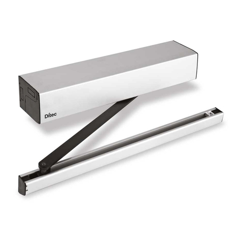
DITEC ENTREMATIC HA9 Service manual

info.ditec.ca@entrematic.com
www.ditecentrematic.ca
info.ditec.us@entrematic.com
www.ditecentrematic.us
HA9 Manual V.1.3
1019956
DITEC HA9 LOW ENERGY
SWING OPERATOR
Installation & Instruction Manual
READ AND FOLLOW ALL INSTALLATION INSTRUCTIONS CAREFULLY!
FAILURE TO DO SO MAY RESULT IN PERSONAL INJURY OR PROPERTY DAMAGE!
•This product is to be installed on the interior side of the door.
•Install only on a properly operating and balanced door.Adoor that is operating improperly could cause severe
injury. Before installing the operator, have qualified service personnel make repairs to cables, and other hardware.
•Before installing the operator,remove or make inoperative, all locks (unless mechanically and/or electrically
interlocked to the power unit), all activation units and accessories that may be connected to the door.
•Acommercial/industrial door operator that has exposed moving parts capable of causing injury to persons or
employs a motor deemed indirectly accessible by virtue of its location above the floor shall include:
- Install the door operator at least 2.4m (8ft) or more above the floor,and/or
- If the operator must be installed less than 2.4m (8ft) above the floor, then exposed moving parts must be
protected by covers or guarding provided by the operator manufacturer.
•The control unit MUST be located: (1) within the sight of the door, and (2) at a minimum height of 1.5m (5ft) above
the floors, landings, steps, or any other adjacent walking surface and (3) away from all moving parts of the door.
•Install the Entrapment Warning Placard next to the control station in a prominent location if applicable.
•Toreduce the risk of injury to persons - Use this system only with pedestriandoors.
•Do not connect the operator to a power supply until instructed to do so. Connection of the high voltage supply
should be done by a qualified professional and within the guidelines of the enforced local electrical codes.
•HIGH VOLTAGE (INCOMING 115 VAC) WIRES AND LOW VOLTAGEWIRES CANNOT SHARE THE SAME
ACCESS HOLE. HIGH VOLTAGEWIRES MUST BE ROUTED AND SECURED AWAYFROM ALL LOW
VOLTAGEWIRES.
Entrematic Canada Inc. Entrematic USAInc.
TollFree: 1-877-348-6837 TollFree: 1-866-901-4284

Entrematic Canada Inc.
Toll Free: 1-877-348-6837
info.ditec.ca@entrematic.com
www.ditecentrematic.ca
Entrematic USA Inc.
Toll Free: 1-866-901-4284
info.ditec.us@entrematic.com
www.ditecentrematic.us
Pg. 3
HA9 Manual V. 1.3
1019956
Table of Contents
1.1 Typical Installation Flow Chart
1.2 Completed/Typical Automatic Door Installation
1.3 Replacement Parts
1.4 Important Information
1.5 Compliance Codes and Standards
1.6 Technical Specification
1.7 How HA9 Works
1.8 Controller Unit HA9 Functions
1.9 Extension Unit EXU-SI Functions
1.10 Extension Unit EXU-SA Functions
1.11 Consideration Of Surroundings
1.12 Before Installation
1.13 Operator Type And Handing
2.1 Pre-Mounting Header Box Instructions
2.2 Push Header Installation
2.3 Pull Header Installation
2.4 Double Egress Header
2.5 Electrical Connection
2.6 Change Configuration
2.7 Motor/Gearbox Reinstallation
3.1 Push Arm Components and Configurations
3.2 Push Arm Installation
3.3 Pull ArmInstallation
4.1 HA9 Control
4.2 Extension Units
4.3 Extension Units EXU-SI
4.4 Extension Units EXU-SA
5.1 Back Check And Latch Adjustment (Door Stop)
5.2 Micro Switch
5.3 Sync Cable For Double Doors
5.4 Auto-Learn (Back Check And Latch Check)
5.5 One/Two Push LRN Button Function
5.6 LRN Button For Double Doors
5.7 LRN With Advanced Settings
5.8 Revert To Default Values “Back And Check”
5.9 General Adjustment
5.10 Reducing/Increasing “Spring Pre-Tension” (SPTE)
6.1 Connection Of Activation Units And Accessories
6.2 Adjusting Parameters
7.1 Overhead Presence Detection (OPD)
7.2 Lock Kick
7.3 Lock Unlock
8.1 Additional Sensors/Knowing Act Devices
8.2 Header Cover Installation
8.3 Safety Decals
8.4 Safety Sticker Placement Example
9.1 Common Faults
9.2 Error Indication
10.1 Service/Maintenance
11.1 Manufacturing Information
1.0 GENERALINFORMATION 4
2.0 OPERATOR INSTALLATION 17
3.0 ARM INSTALLATION 26
4.0 CONTROL UNITS 33
5.0 OPERATOR TUNING 37
6.0 ACTIVATION UNITS & ACC 45
7.0 ADVANCED SETTINGS 47
8.0 INSTALLATION WRAP UP 49
9.0 TROUBLESHOOTING 52
10.0 SERVICE/MAINTENANCE 54
11.0 MANUFACTURING 55
1.0 GENERAL INFORMATION 4

Entrematic Canada Inc.
Toll Free: 1-877-348-6837
info.ditec.ca@entrematic.com
www.ditecentrematic.ca
Entrematic USA Inc.
Toll Free: 1-866-901-4284
info.ditec.us@entrematic.com
www.ditecentrematic.us
Pg. 5
HA9 Manual V. 1.3
1019956
1.2 Completed/Typical Automatic Door Installation
1.0 GENERAL INFORMATION
Backing Material
(Reinforcement)
Header Cover
Arm
Motor/Gearbox
Header Body
Control Board
ANSI Stickers
Knowing Act
Device
Swing Door
Strike Style
Frame
Hinge Style

Entrematic Canada Inc.
Toll Free: 1-877-348-6837
info.ditec.ca@entrematic.com
www.ditecentrematic.ca
Entrematic USA Inc.
Toll Free: 1-866-901-4284
info.ditec.us@entrematic.com
www.ditecentrematic.us
Pg. 6
HA9 Manual V. 1.3
1019956
1.3 Replacement Parts
Replacement Parts
Replacement Parts
Item
Category
Part No.
Description
Item
Category
Part No.
Description
1
Push Arm
W7-200
Complete Push Arm-Clear
6
Power Supply Kit
WL-
RS-25-24
(with 17.5” rod)
PWRKIT
Power Supply Kit
W7-205
Complete Push Arm-
Bronze
7
Rocker Switch
W8-804
ON/ OFF/ HOLD OPEN
3 position switch
(with 17.5” rod)
W5-502C
Cast portion - Clear
8
Motor/Gearbox
W8-801
Motor/Gearbox Kit
W5-502B
Cast portion - Bronze
9
Controls
W8-802
HA9 Controller
W5-500C
Extended Rod 22"- Clear
10
Conduit
W8-803
Conduit Bracket Kit
W5-500B
Extended Rod 22"- Bronze
11
Shaft Adaptor
W8-805
Shaft Adaptor
2
Pull Arm Track -
Long
W5-551
Pull Track Assembly Long -
Clear
12
Sync Cable
W8-850
Sync Cable
13
Program Selector
W8-856
Surface Mount Box
W5-556
Pull Track Assembly Long -
Bronze
14
W8-857
2 Position PSK-2
15
W8-858
Spare Key PSK/PS-4C
3
1-9/16” x 2-3/8”
Reveal Spacer
Extrusion
W8-862-
BLK
Spacer Assy. - Black
16
W8-859
4 Position w/Key PS-4C
W8-862-SI
Spacer Assy. - Silver
17
Extension Units
W8-860
EXU-SA
4
Pull Arm
W5-512C
Pull Arm - Clear
18
W8-861
EXU-SI
W5-512B
Pull Arm - Bronze
19
Stop Arm Kit
W8-851
Stop Arm Kit
5
Micro Switch Kit
W8-852
Lock Kick Switch, Cam &
Cable
20
Lock Spacer Kit
W8-853
Lock Spacer Kit
21
Allen Key Head
Nut Kit
W8-854
Allen Key Head Nut Kit
1.0 GENERAL INFORMATION
8
1
10
9
11
16
15
14
13
17
18
12
3
2
4
5
6
21
20
19
7

Entrematic Canada Inc.
Toll Free: 1-877-348-6837
info.ditec.ca@entrematic.com
www.ditecentrematic.ca
Entrematic USA Inc.
Toll Free: 1-866-901-4284
info.ditec.us@entrematic.com
www.ditecentrematic.us
Pg. 7
HA9 Manual V. 1.3
1019956
1.4 Important Information
Intended Use
The door is designed to offer continuous use, a high degree of safety and maximum lifetime.
The Entrematic HA9 is an automatic swing door operator developed to facilitate entrances to buildings and within buildings
through swing doors. The HA9 is a low-energy operator using a DC motor and a gear-reduction system to drive an arm
system, which opens the door. It is to be installed indoors where it is suitable for almost all types of external and internal
swing doors. This widely-used operator can be found on applications ranging from handicapped-access in private homes
to high-traffic retail operations.
The motor and gear system are combined into a compact unit mounted alongside the control unit within the cover. The
operator is connected to the door leaf with different arm systems.
Safety Precautions
•Do not climb on door parts.
•Do not let children play with the door or the fixed controls.
Be sure to complete a risk assessment according to "Guide for Installers of Powered Pedestrian Swing Doors" (PRA-
0006) and fill in the "Site Acceptance Test" (PRA-0007) before taking the door into operation.
To avoid bodily injury, material damage and malfunction of the product, the instructions contained in this manual must be
strictly observed during installation, adjustment, repairs and service etc. Factory authorized training is required to carry out
these tasks safely. Only Ditec Entrematic -trained technicians should be allowed to carry out these operations.
Electronic Equipment Interference
The equipment complies with the European EMC directive (US market FCC Part 15), provided installed according to
Installation and Service manual.
The equipment may generate and use radio frequency energy and if not installed and used properly, it may cause
interference to radio, television reception or other radio frequency type systems.
If other equipment does not fully comply with immunity requirements interference may occur.
There is no guarantee that interference will not occur in a particular installation. If this equipment does cause interference
to radio or television reception, which can be determined by turning the equipment off and on, the user is encouraged to
try to correct the interference by one or more of the following measures:
•Re-orient the receiving antenna.
•Relocate the receiver with respect to theequipment.
•Move the receiver away from the equipment.
•Plug the receiver into a different outlet so that equipment and receiver are on different branch circuits.
•Check that protective earth (PE) is connected.
If necessary, the user should consult the dealer or an experienced radio/television technician for additional suggestions.
Environmental Requirements
Ditec Entrematic products are equipped with electronics and may also be equipped with batteries containing materials
which are hazardous to the environment. Disconnect power before removing electronics and make sure it is disposed of
properly according to local regulations (how and where) as was done with the packaging material.
Glazing Materials
The glazing material for swing doors shall comply with ANSI Z97.1.
1.0 GENERAL INFORMATION

Entrematic Canada Inc.
Toll Free: 1-877-348-6837
info.ditec.ca@entrematic.com
www.ditecentrematic.ca
Entrematic USA Inc.
Toll Free: 1-866-901-4284
info.ditec.us@entrematic.com
www.ditecentrematic.us
Pg. 8
HA9 Manual V. 1.3
1019956
1.5 Compliance Codes and Standards
The operator complies with the following codes and standards:
•UL STD.325 & ANSI/BHMA STD. A156.19; Fire rated UL STD. 10 (b); UL STD. 10(c); NFPASTD. 252
•CAN/CSA STD. C22.2 NO. 247 & CAN/ULC STD.S104
•Under No Circumstances shall the Certification Label of the HA9 operator be tampered, modified
or removed!
•It is the responsibility of the final installer and/or installation company, to certify that the final
completed operator is installed in accordance with local building codes and applicable laws.
1.6 Technical Specifications
Manufacturer:
Ditec Entrematic
Type:
HA9
Power supply:
120 V AC +10/-15%, 50/60 Hz
Power consumption:
Max. 75 W (AVG. 25 W)
Auxiliary voltage:
24 V DC, max. 400 mA
Internal control fuse:
2 x T 6,3 AH 250 V
Max. weight/width:
Push arm: 200 lbs./48" (94.3kg/1219mm)
Note: Refer to the appropriate standard (ANSI A156.10 or ANSI
A156.19) for door forces and speeds as related to door weight
and width.
Door width:
Electro-mechanical locking device:
36-48” (914-1219 mm)
Selectable: 12V DC, max. 500 mA / 24 V DC, max. 250 mA
Door weight:
100-200 lb. (45-90 kg)
Door opening angle:
Push arm:80° - 110°, with reveal 0 - 14" (0 - 356 mm)
Pull arm: 80° - 110°, with reveal 0 - 2 ⅜” (0 - 60.33 mm)
Opening time (0° - 80°):
variable between 3 - 6 seconds
Closing time (90° - 10°):
variable between 3 - 6 seconds
HOLD open time:
1,5-30 seconds
Ambient temperature:
-4 °F to +113 °F (-20 °C to +45 °C)
Degree of protection:
IP20
Degree of protection, control actuators:
IP54
Relative humidity (non-condensing):
Max. 85%
Standards:
The HA9 complies with IEC 335-1, ANSI/BHMA A156.19 and UL 325.
1.0 GENERAL INFORMATION

Entrematic Canada Inc.
Toll Free: 1-877-348-6837
info.ditec.ca@entrematic.com
www.ditecentrematic.ca
Entrematic USA Inc.
Toll Free: 1-866-901-4284
info.ditec.us@entrematic.com
www.ditecentrematic.us
Pg. 9
HA9 Manual V. 1.3
1019956
1.7 How HA9 Works
The low energy swing door operator HA9 uses a motor and a gear-reduction system to drive an arm system, which opens
the door. Closing power is provided by a motor and a clock spring.An electronic control unit uses a motor encoder and a
microprocessor to control the door’s movement.
Opening
When an opening signal is received bythe control unit, the door is opened at the operator-adjusted opening speed. Before
the door is fully open at back check, it slows automatically to low speed. The motor stops when the selected door opening
angle has been reached. The open position is held by the motor. If the door is obstructed while opening, it will either stall or
stop which can be selected with a DIP switch(SOS).
•When stalling - the door will continue to try to open during the hold open time.
•When stopping - the door will, even if hold open time has not expired, close after 2 seconds.
Closing
When the hold open time has elapsed, the operator will close the door automatically, using spring force and motor. The door
will slow to low speed at latch check before it reaches the fully closed position. The door is kept closed by spring power or
extended closing force by the motor.
1.0 GENERAL INFORMATION

Entrematic Canada Inc.
Toll Free: 1-877-348-6837
info.ditec.ca@entrematic.com
www.ditecentrematic.ca
Entrematic USA Inc.
Toll Free: 1-866-901-4284
info.ditec.us@entrematic.com
www.ditecentrematic.us
Pg. 10
HA9 Manual V. 1.3
1019956
1.8 Control Unit HA9 Functions
Power failure
During power failure the operator acts as a door closer with controlled closing speed.
Spring force
The operator is delivered with spring pre-tension factory set to the maximum recommended value of 210°. If necessary,
the spring tension can be electronically adjusted with a potentiometer to required closing force. The arm must also be
relocated on the spindle.
Extended closing force/torque (CLTQ)
If the potentiometer CLTQ is set to 0°, the door will close with normal spring power. If the potentiometer is turned clockwise,
the motor will increase the closingforce/torque.
Power assist (POAS)
If the potentiometer POAS is set to 0°, the door gives no power assist. If the potentiometer is turned clockwise, the motor will
give/increase power assist when the door is openedmanually.
Push and go (PAG)
DIP-switch to select PUSH and GO, ON or OFF. PUSH and GO is available from any door position. PUSH and GO is not
active in program selector setting OFF.
Note: Power Assist or Push and Go functions will not work at the same time (one or the other only).
Sensor & Knowing Act Devices, frame mounted
When a sensor is mounted on the frame or operator cover just above the swing side of the door, it will–when activated–either
keep the door open or closed. The sensor is not active during opening and closing. Lock-out signal must be connected for
proper function.
•A closed door will not open, if the sensor detects activity in the field.
•An open door will not close, if the sensor detects activity in the field.
•During opening, the door will continue to open, even if the sensor detects activity in the field.
•During closing, the door will continue to close, even if the sensor detects activity in the field.
•The sensor is not active in program mode OFF ormanually opened door.
Mat
Mat safety means that:
•A closed door will not open,if someonesteps onthe mat.
•Anopen doorwillnotclose,ifsomeonestepson themat.
•Duringopening, thedoorwillcontinueto open,evenifsomeonesteps onthe mat.
•Duringclosing,thedoorwillcontinuetoclose,even ifsomeone steps onthemat.
•Openingimpulsesarepreventedduringclosing,if someone stepsonthemat.
•ThematisnotactiveinprogrammodeOFF or manuallyopeneddoor.
1.0 GENERAL INFORMATION

Entrematic Canada Inc.
Toll Free: 1-877-348-6837
info.ditec.ca@entrematic.com
www.ditecentrematic.ca
Entrematic USA Inc.
Toll Free: 1-866-901-4284
info.ditec.us@entrematic.com
www.ditecentrematic.us
Pg. 11
HA9 Manual V. 1.3
1019956
1.9 Extension Unit EXU-SI Functions (Standard)
KlLL Function
•If KILL circuit is closed, the control will ignore all signals and close door(s) at normal speed.
•When KILL is no longer active, operator will resume normal operation.
•If KILLfunction must have manual reset, jumper must be removed and reset button connected to terminal No. 8
and Ground.
•The lock will lock when KILLis active regardless of program selector setting.
•The function of the lock can be changed during KILL Section Changing group of parameters (Level 2)
In the event that the KILL circuit is activated, all Safety Functions of the door will be overridden
causing the door to close even though an object or person may be in the door's path of travel,
and therefore may be subject to injury. This mode of operation is most generally used to isolate
an area in the event of afire.
Function of locks
•The lock output only works when the function switch is in OFF or EXIT. If no function switch is used OFF or EXIT must be
connected to GND (0 VDC).
•The control has an available output of DC for externallocks
•DIP-switches to select 12 or 24 V DC, locked with or without power
•DIP-switch for lock release and potentiometer for openingdelay
•DIP-switch for lock kick if door is not fully closed, to overcome binding in the locking device during closing
•Input to unlock signal from lock. Potentiometer for opening delay is to be set to max.As soon as unlock signal is received
the door will start to open. The output signal shall be active low.
Program selector
•Input for OPEN, EXIT and OFF (if no program selector, AUTO is default).
Activation Signal
•Input for OUTER signal, KEY and OPEN/CLOSE activationsignal.
OPEN/CLOSE Activation Signal
The signal will open the door and the door will stay open until a new signal is given.
If no signal is given the door will close after 15 minutes. This can be made infinite
by changing group of parameters Section Changing group of parameters.
OPEN/CLOSE signal works only in program selection ON.
1.0 GENERAL INFORMATION
EXU-SI
(for security functions)
P/N: W8-861

Entrematic Canada Inc.
Toll Free: 1-877-348-6837
info.ditec.ca@entrematic.com
www.ditecentrematic.ca
Entrematic USA Inc.
Toll Free: 1-866-901-4284
info.ditec.us@entrematic.com
www.ditecentrematic.us
Pg. 12
HA9 Manual V. 1.3
1019956
1.10 Extension Unit EXU-SA Functions (Optional)
Presence signal approach, door mounted
The presence impulse is active during fully open and closing. The sensor is mounted to the approach side of the door.
Once the door is closed, the sensor is ignored and will not be active until the next impulse is received.
When installed as a pair of doors, the presence impulse signal will re-open both doors.
The sensor is not active in program mode OFF,manually opened door (Power Failure
Mode), Kill Mode.
Presence detection swing path, door mounted
When a sensor that is mounted on the swing side of a door detects an object, it will send a command to the control unit to
stall the door. If the control unit has received a short signal from the sensor and there is still hold open time left on the
control unit, the door will continue on its way open if the object has cleared. The inhibit/blanking potentiometer can be
adjusted so that the sensor will avoid detecting a wall or object near the full open position. Presence detection has a higher
priority than presence signal.
When installed as a pair of doors the presence detection signal will stop both doors, except
for double egress doors. The behavior for double egress doors can be changed. The sensor
is not active in program mode OFF, manually opened door.
Monitored safety sensors
Both presence impulse and presence detection can be monitored. If a sensor
becomes defective, the operator will not accept any impulses and will then work as a
manual door closer.
Open door indication
A relay output is used to indicate an opening cycle or a specific position of the door.
The indication position is set byadjusting the inhibit/blanking potentiometer.
Error indication
A potential free contact COM/NO/NC for external error indication.
1.0 GENERAL INFORMATION
EXU-SA
(for safety functions)
P/N: W8-860

Entrematic Canada Inc.
Toll Free: 1-877-348-6837
info.ditec.ca@entrematic.com
www.ditecentrematic.ca
Entrematic USA Inc.
Toll Free: 1-866-901-4284
info.ditec.us@entrematic.com
www.ditecentrematic.us
Pg. 13
HA9 Manual V. 1.3
1019956
1.11 Before Installation
•All wiring must conform to standard wiring practice in accordance with national and local wiring codes.
•An incorrectly installed or improperly adjusted door operator can cause property damage or personal injury.
These instructions should be followed to avoid the possibility of misapplication or maladjustment.
•All dimensions are given in inches (millimeters), unless otherwisenoted.
Door/Frame Preparation
•Before installation, verify door frame is properly reinforced and is well anchored in the wall.
•Concealed electrical conduit, and concealed switch or sensor wires should be pulled to the frame before proceeding.
Suggested Fasteners for Frame
•#14 x 2-3/4" (70mm) long sheet metal screws.
Suggested Fasteners for Door
•#12, #14, Wood screws, Sheet Metal screws, Self-tapping screws of varying lengths depending on applications.
The fastener components listed above are merely suggestions. Atechnician should use their best
discretion to determine what components they’ll need to complete the job.
Do Not use Drywall Screws or Hollow Wall Anchors to mount the backer plate. The header
must be strong enough to support 200lbs.
Shipping inspection
Verify that the order was shipped complete and correct, including model number, door handing, color, and header width.
•If any of the above items are not correct, do not attempt to install until all conditions are correct
•Report any incorrect items to the general contractorimmediately.
NO CLAIMS FOR SHORTAGES WILL BE ALLOWED UNLESS
REPORTED WITHIN 24 HOURS OF RECEIPT OF SHIPMENT.
1.0 GENERAL INFORMATION

Entrematic Canada Inc.
Toll Free: 1-877-348-6837
info.ditec.ca@entrematic.com
www.ditecentrematic.ca
Entrematic USA Inc.
Toll Free: 1-866-901-4284
info.ditec.us@entrematic.com
www.ditecentrematic.us
Pg. 14
HA9 Manual V. 1.3
1019956
Door/ General Tips/ Safety concerns
•If there are sharp edges after drilling the cable outlets, chamfer the edges to avoid damage to the cables.
•For enhanced security and vandalism protection, always mount the operator access in the interior of a
building whenever possible.
•Make sure the ambient temperature is in the range specified in section Technical specification.
•Make sure that the power is off before installing.
•Make sure that the door leaf and the wall are properly reinforced at the installation points.
•Unpack the operator and make sure that all parts are delivered in accordance with the packing note and that
the operator is in good mechanical condition.
•Ensure proper material is being used for the door leaves and that there are no sharp edges. Projecting parts shall
not create any potential hazards. If glass is used bare glass edges shall not come in contact with other glass.
Toughened or laminated glass are suitable glasses.
•Ensure that entrapment between the driven part and the surrounding fixed parts due to the opening
movement of the driven part is avoided. The following distances are considered sufficient to avoid
entrapments for the parts of the body identified;
•For fingers, a distance greater than 1” (25mm) or less than 5/16” (8mm).
•For heads, a distance greater than 8” (200mm).
•For feet, a distance greater than 2” (50mm).
•For the whole body, a distance greater than 20”(500mm).
•Danger points shall be safe guarded up to a height of 8’ (2.5 m) from the floor level.
•The operator shall not be used with a door set incorporating a wicket door.
1.0 GENERAL INFORMATION

Entrematic Canada Inc.
Toll Free: 1-877-348-6837
info.ditec.ca@entrematic.com
www.ditecentrematic.ca
Entrematic USA Inc.
Toll Free: 1-866-901-4284
info.ditec.us@entrematic.com
www.ditecentrematic.us
Pg. 15
HA9 Manual V. 1.3
1019956
1.12 Consideration of Surroundings
Floor Space Requirements for Wheel Chair Maneuvering - Americans with Disabilities Act (ADA)
The owner may request the activation device location; however, the press switch must be in view of the door and not directly
on the door or frame. Please refer to ANSI 117.1 Safety Code for further guidelines on switch requirements.
Position# 1
Minimum 2' (610mm)
Activation switches shall be at minimum height of
36" (914.4mm) and maximum height of 48"
(1219mm) from finished floors or as specified by
a local Authority Having Jurisdiction.
Individual who uses wheelchair needs a minimum
of 48” clearance to the door swing for doors in
sequence application.
From door latch
Position# 2
Minimum 5' (3048mm)
from door face
External and Internal Factors
Door Condition
Door must move easily open and close (latch) without excessive force; weather stripping and
Threshold must not interfere with door movement.
Reveal
For out swing (Push) doors, the reveal must be within the range of 0" to 14" (356mm). For in
swing (Pull) doors, 0" to 2 ⅜” (60mm) for special reveals is allowed
-
for all others consult
factory.
Wind
When installing on a door in a strong wind condition area, special adjustments should be made
to the doorstop position and controller adjustments.
Power/Control Wires
Check that the electrical feed, all conduits, and electrical junction boxes (for push plates or
other activation devices, if required) are correctly located in accordance with final approved
shop drawings and within the guidelines of the enforced local electrical codes.
Required Tools for Installation:
•Torx, T10
•Allen Wrench Set
•Nut Driver, 5mm
•Screwdrivers: Flat, Philip, 5/16" Hex. Nut
•Power Drill and Drill Bits
•Additional Fasteners Depending Surface
•Level
•Shims
•Center Punch
•Tape Measure
•Silicone Sealant
•Hand Saw/ Power Saw
•Wire Stripper
1.0 GENERAL INFORMATION

Entrematic Canada Inc.
Toll Free: 1-877-348-6837
info.ditec.ca@entrematic.com
www.ditecentrematic.ca
Entrematic USA Inc.
Toll Free: 1-866-901-4284
info.ditec.us@entrematic.com
www.ditecentrematic.us
Pg. 16
HA9 Manual V. 1.3
1019956
1.13 Operater Type and Handing
The system is either a Push or Pull type configured for left or right door handing. Door handing is determined bystanding
with your back to the hinges. The side to which the door normally opens (right or left) is the handing of the door. The
diagram below shows a right-handed door.
Push
Pull
1.0 GENERAL INFORMATION

Entrematic Canada Inc.
Toll Free: 1-877-348-6837
info.ditec.ca@entrematic.com
www.ditecentrematic.ca
Entrematic USA Inc.
Toll Free: 1-866-901-4284
info.ditec.us@entrematic.com
www.ditecentrematic.us
Pg. 17
HA9 Manual V. 1.3
1019956
2.1 Pre-Mounting Header Box Instructions
Disassemble parts for installation
Remove the cover from the assembly by gently prying with a screwdriver. Once the snaps are clear, pull the cover outwards
with minimal effort. Carefully set the cover in a location where it will not be damaged.
Mark spindle center on the bottom edge of header and remove the motor/gearbox from the back plate by loosening 4
motor/gearbox nuts.
The spindle center must be marked prior to removing the motor/gearbox to locate back plate to door
frame and reinstallation.
2.0 OPERATOR INSTALLATION
4
1 (captured in unit)
3
2

Entrematic Canada Inc.
Toll Free: 1-877-348-6837
info.ditec.ca@entrematic.com
www.ditecentrematic.ca
Entrematic USA Inc.
Toll Free: 1-866-901-4284
info.ditec.us@entrematic.com
www.ditecentrematic.us
Pg. 18
HA9 Manual V. 1.3
1019956
2.2 Push Header Installation
The Header Box on push installations is mounted flush to the bottom of the door frame. It may require solid backing
material to compensate for the thickness of the door frame.
Holes can be made anywhere in header to secure. All holes MUST be drilled into substantial
support (studs, blocks, framing, etc.). This diagram may not reflect your installation.
Do Not use Drywall Screws or Hollow Wall Anchors to mount the back plate / header.
Before fastening header box to the door frame, dry fit header by positioning the backer plate flush to the bottom of the
door jamb and the previously marked spindle center line is 8¼“ (210mm) from the door hinge/pivot.
1. Mark locations to drill frame to match the predrilled access holes for high and low voltage wires and mounting holes. If
the holes are not at a convenient location, you can drill the backer plate to suit.
2. Anchor the back plate to the wall with minimum of six (6) - #14 x 1" Pan Quad Type A screws (provided). You may
need to provide other screws if your installation requires it. The locations of the screws on the header are application
dependent but (2) of the screws must fasten the back plate directly to the door’s vertical jambs on the hinge side.
3. Add additional screws to fasten the header back plate to the door frame approximately 12" to 16" (305mm to
406mm) apart. The header must be strong enough to support 200 lbs. (90kg).
For most applications, the header is equal to door opening plus 3" (76mm). This allows for a 1½"
(38mm) space on either side of the Header Box. However, it MUST be installed 1½" (38mm) from hinge
side for all Push installations, regardless if header is sized appropriately to anchor the header box
properly to the frame.
2.0 OPERATOR INSTALLATION
Backing Material
Flush
5/64" –43/64" (2-17mm)

Entrematic Canada Inc.
Toll Free: 1-877-348-6837
info.ditec.ca@entrematic.com
www.ditecentrematic.ca
Entrematic USA Inc.
Toll Free: 1-866-901-4284
info.ditec.us@entrematic.com
www.ditecentrematic.us
Pg. 19
HA9 Manual V. 1.3
1019956
Push Header Backer Plate Positioning
4. Complete high voltage and control board connections (see section 2.5).
5. Reinstall motor/gearbox (see section 2.6).
6. Install arm (see section 3.1).
2.0 OPERATOR INSTALLATION
Hinge
Side
Predrilled Electrical Holes (2)
Motor/Gearbox Mounts
Predrilled Mounting Holes (4)
Strike
Side
Spindle Center
8¼” (210mm)
1½” (38mm)
Door Opening Width + 3” (76mm)
Hinge Center

Entrematic Canada Inc.
Toll Free: 1-877-348-6837
info.ditec.ca@entrematic.com
www.ditecentrematic.ca
Entrematic USA Inc.
Toll Free: 1-866-901-4284
info.ditec.us@entrematic.com
www.ditecentrematic.us
Pg. 20
HA9 Manual V. 1.3
1019956
2.3 Pull Header Installation
The Header Box on pull installations is mounted 1 ⅜” (35mm) above the bottom of the door frame. It may require solid
backing material to compensate for the thickness of the door frame.
Holes can be made anywhere in header to secure. All holes MUST be drilled into substantial
support (studs, blocks, framing, etc.). This diagram may not reflect your installation.
Do Not use Drywall Screws or Hollow Wall Anchors to mount the back plate / header.
1. Before fastening header box to the door frame, dry fit header by positioning the backer plate flush to the bottom of
the door jamb and the previously marked spindle center line is 8¼“ (210mm) from the door hinge/pivot.
2. Mark locations to drill frame to match the predrilled access holes for high and low voltage wires and mounting
holes. If the holes are not at a convenient location, you can drill the backer plate to suit.
3. Anchor the back plate to the wall with minimum of six (6) - #14 x 1" Pan Quad Type A screws (provided). You may
need to provide other screws if your installation requires it. The locations of the screws on the header are
application dependent but (2) of the screws must fasten the back plate directly to the door’s vertical jambs on the
hinge side.
4. Add additional screws to fasten the header back plate to the door frame approximately 12" to 16" (305mm
to 406mm) apart. The header must be strong enough to support 200 lbs. (90kg).
For most applications, the header is equal to door opening plus 3" (76mm). This allows for a 1½"
(38mm) space on either side of the Header Box. However, it MUST be installed 1½" (38mm) from hinge
side for all Push installations, regardless if header is sized appropriately to anchor the header box
properly to the frame.
2.0 OPERATOR INSTALLATION
Backing Material
1 ⅜” (35mm)
Reveal 0 - 2 ⅜” (60mm)
Other manuals for ENTREMATIC HA9
1
Table of contents
Other DITEC Door Opening System manuals

DITEC
DITEC DAS107PLUS User manual

DITEC
DITEC ENTREMATIC HA9 User manual

DITEC
DITEC DAS107PLUS User manual

DITEC
DITEC OLLY C Manual

DITEC
DITEC DOR User manual

DITEC
DITEC Sprint Manual

DITEC
DITEC Flash C User guide

DITEC
DITEC Entrematic Hurricane DS20 Manual

DITEC
DITEC OLLY M Manual

DITEC
DITEC entrematic HA8-LP Service manual
Popular Door Opening System manuals by other brands

Automatic Technology
Automatic Technology Dominator Tempo ATS-2AM instruction manual

Overhead door
Overhead door RHX NEMA 7 installation manual

TPG
TPG AXIM PR-7000 Series Technical support

ENFORCER
ENFORCER Enforcer E-942FC-600SQ installation manual

Steren
Steren MERIK RM-950 user manual

Assa Abloy
Assa Abloy G-CO-CS Mounting instructions