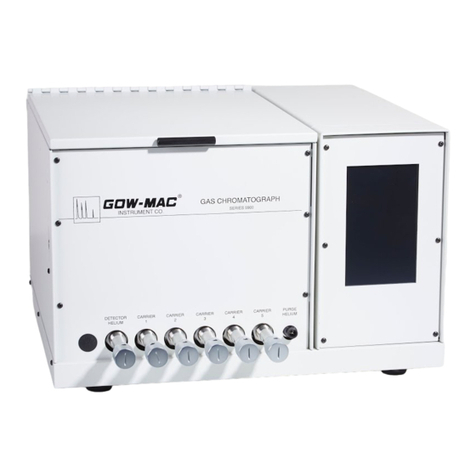
Gow-Mac 5900 Series Parts list manual

Series 5900
Discharge Ionization Detector
Gas Chromatograph
Series 5900: 105-125 VAC, 60 Hz
Series 5902: 200-240 VAC, 50 Hz
July 2021
Rev. 5
READ INSTRUCTIONS
BEFORE OPERATING
277 Brodhead Road, Bethlehem, PA 18017-8600 U.S.A. Tel: (610) 954-9000
OPERATING MANUAL


3
Contents
SECTION 1 - SAFETY ..................................................................................... 5
SECTION 2 - SPECIFICATIONS ..................................................................... 7
SECTION 3 - INSTALLATION ......................................................................... 9
SECTION 4 - OPERATING CONTROLS ....................................................... 17
SECTION 5 - OPERATION OF THE SERIES 5900 DID GC ......................... 23
SECTION 6 - MAINTENANCE & SERVICE .................................................. 31
SECTION 7 - VALVES ................................................................................... 33
SECTION 8 - REPLACEMENT PARTS ....................................................... 37
SECTION 9 - ADDENDUM - DUAL O2 TRAPS ............................................ 39

4GOW-MAC Instrument Co.
CAUTION CAUTION
CAUTION
This instrument was designed for DRY sample applications only!
Care must be taken to make sure only moisture-free samples are
introduced into the system.
GOW-MAC®Instrument Company is not responsible for damage to
equipment caused by exposure to hydrolyzed samples.

5
GOW-MAC Series 5900 DID GC R.5, 0721
Section 1
Safety
1-1 Thissectionisdesignedtobringspecialattentiontospecicareasorpracticesthatmayposeparticular
hazards to personnel and/or equipment safety only. For complete installation instructions, see Section
3.
It is in the operator’s best interest to read this section to ensure the safe operation of the instrument.
1-2 BURN HAZARDS
The detector, column, and column oven lid may reach very high temperatures and remain HOT for
several hours after the instrument has been shut down. Wear protective gloves to prevent painful burns
resulting from contact with the hot surfaces.
1-3 ELECTRICAL HAZARDS
A. This instrument employs voltages that are dangerous. EXTREME caution must be exercised when
working with this equipment. Disconnect the instrument from all power sources before removing front, side or
back panels and exposing potentially dangerous voltages.
B. DO NOT handle exposed voltage terminations until the load and/or supply has be discharged (grounded). An
unloaded supply may take up to 15 seconds to fully discharge.
C. Make sure that the actual line voltage is the proper value for which the instrument was designed. (For
properly grounded outlet only).
D. DO NOT overload the AC outlet with other electrical equipment.
E. Adhere to the color coding descriptions when hooking up electrical connections.
F. Repair or replace faulty or frayed wiring IMMED I ATELY.
1-4 COMPRESSED GAS CYLINDERS
Compressed gas cylinders are potential sources for serious accidents, injuries and even death if proper
precautions and safety practices are not followed. Therefore, during handling and use of these gases,
be certain to use applicable safety precations described by your local compressed gas supplier, the
Compressed Gas Association, and/or O.S.H.A. regulations.
A. Read the label on all cylinders BEFORE using to identify the cylinder contents. If the label is
illegible, return the cylinder to the supplier. DO NOT ASSUME THE CONTENTS.
B. All gas cylinders in use and in storage MUST be secured to an immovable structure to prevent accidental
falling or movement. Read the relevant safety codes.
C. DO NOT move or transport cylinders with regulators attached or without safety cap screwed on over the
valve system.
D. Store or move cylinders ONLY in the vertical position.
E. Store cylinders in a well ventilated area away from heat or ignition sources.
F. When installing tubing, provide ONLY approved, adequate pressure reducing regulators and pressure relief
devices to prevent over pressurizing the tubing and equipment.

6GOW-MAC Instrument Co.
WARNING
READ CGA AND/OR O.S.H.A. PROCEDURES FOR PROPER HANDLING OF COMPRESSED GAS
CYLINDERS.
1-5 GENERAL
A.Performperiodicleakchecksatallttingareas.TheGOW-MACModel21-070MiniGasLeak
Detectorisrecommendedtondsmallleaks.
B. Keep combustibles away from gas cylinders and eliminate ignition sources.
C. DO NOT place papers, charts, samples, etc. on top of the GC.
D.Maintainadequateventilation.Ventallgasestotheoutside.DONOTallowammableand/ortoxic
wastes to accumulate.
E. De-pressurize supply gas piping before working on it.

7
GOW-MAC Series 5900 DID GC R.5, 0721
Section 2
Specications
2-1 The GOW-MAC Series 5900 DID is a rugged, compact gas chromatograph designed for the analysis of
low concentrations of impurities in base gases.
2-2 The right-hand section of the Series 5900 contains the electronics necessary for the proper operation
of the gas chromatograph. A 7” LCD digital touchscreen will control the DID high voltage, polarization
voltage, column and detector temperatures, valves and signal output. Contained within the internal
housing are the signal processing and support electronics for column oven and DID.
2-3 The center section of the chromatograph houses the column oven, a purged housing which contains
thepneumaticallyactuatedvalves,theDIDdetector,andbellowsmeteringvalvestocontrolgasowto
columns,detectorandpurgegas.AllinletttingsandcolumnttingsareVCR®type.Therearealso
exitportsformeasuringcolumnow,purgeowandsampleowwhichare1/8”compressionttings.
There are a maximum of four pneumatically actuated valves mounted inside a purged housing. Refer
tothevalvesectiononthesystemowdiagramtodeterminewhichvalvesareincludedinyourSeries
5900.
2-4 SpecicationsfortheSeries5900DIDGC
General
Dimension 19.5” W x 25” D x 12 1/2” H (48.26 cm x 63.5 cm x 31.75 cm)
Weight Net 50 lbs. (22.68 kg)
Power Requirements Series 5900: 105-125 VAC, 60 Hz, 1100W
Series 5902: 200-240 VAC, 50 Hz, 1100W
Fuse Series 5900: 10 amp
Series 5902: 5 amp
Column Oven
Dimension 10” W x 4 1/2” D x 7 1/2” H (25.64 cm x 11.54 cm x 19.23 cm)
Temperature Ambient to 300 °C
Display Readout 7” LCD Digital Touchscreen
Temperature Control Digital programmable PID controller, solid state output, RTD input,
direct reading, ambient to 300 °C on display screen
Detector
Type Discharge Ionization
Sensitivity 5 ppb CH4
Carrier Gas Grade 6 purity helium (He)
Discharge Gas Grade 6 purity helium (He)
Temperature Range Ambient to 120 °C

8GOW-MAC Instrument Co.
O2 Traps
Dimension 5” W x 6” D x 6” H (12.76cm x 15.24 cm x 15.24 cm)
Temperature Operating: 80 °C
Regnerate: 130 °C (Factory Set)
Display Readout 7” LCD Digital Touchscreen
Brand names used in this manual:
• VCR is a registered trademark of Swagelok Company
• Tygon is a registered trademark of Saint-Gobain
• SulnertisaregisteredtrademarkofRestekCorp.
Gas Flow
Bypass/needlevalveforowcontrolofpurgedhousingowrate.Afrontpanelowmeterisprovidedto
measurethesampleowrate.
Uptosix(6)bellowsmeteringvalvesforseparateowcontrolofcolumns,carriergasesandthedischargegas
dependingontheinstrumentowconguration.
Table 2.1: GC Support Gas Specications
Detector Service Gas Grade, Purity
Supply Pressure (psig)
Recommended Maximum
DID
Carrier and
detector
discharge
Helium
UHP
99.9999%
(note)
100 120
Purge/Valve
Actuator Helium Instrument
99.99% 80 120
Calibration Analysis-
dependent 15 20
Sample Various 15 20
O2 Trap Regenera-
tion H2 UHP 99.999% 20 40
NOTE:ForDIDcarrierservice,UHPhelium,99.9995%purity,mustbefurtherpuriedby
aGOW-MACModel75-810or75-800noblegaspurierorequal.
High Voltage Discharge Ionization Power Supply
Output Voltage : up to 1000 V Max.
Output Current : 10 mA
High Voltage Polarization Power Supply
Output Voltage : up to 500 V
Max. Output Current : 1 mA
ElectrometerAmplier
Circuit :SolidstateFEToperationalamplier

9
GOW-MAC Series 5900 DID GC R.5, 0721
Section 3
Installation
3-1 It is EXTREMELY IMPORTANT that the operator become familiar with this section BEFORE
proceeding with the installation of this instrument.
3-2 Additional Equipment Required
A. Research or Ultra High Purity Helium (He) Carrier Gas: cylinder should be equipped with a NEW
UltraHighPurityRegulatorterminatingina1/4”VCR®tting.
B.HighCapacityCarrierGasPurier(recommendedforGrade5heliumorlower)
C. 1/8” Stainless Steel Tubing, PRE-CLEANED
D. Data Acquisition Software
E. AC Power Source: Series 5900 : 1100 W at 115 V, 60 Hz
Series 5902 : 550 W at 230 V, 50 Hz
WARNING
OPERATING INSTRUCTIONS FOR BOTH MODELS ARE THE SAME, EXCEPT FOR LINE VOLTAGE
REQUIREMENTS. TO PREVENT DAMAGE TO THE INSTRUMENT, MAKE SURE THAT THEAC ELECTRICAL
OUTLET IS THE CORRECT VOLTAGE BEFORE PLUGGING IT INTO THE OUTLET. DO NOT PLUG THE
UNIT IN AT THIS TIME.
F. GOW-MAC P/N 59-595 Accessory Package
Package Includes:
a.)Ultra-highpurityregulatorwithCGA580ttings
b.)Ultra-highpurityregulatorswithCGA350ttings
c.)RegulatorwithCGA580tting
d.)NobleGasPurier:Model75-810(115VAC)or75-812(230VAC)
e.) Metering Valve, 1/8”
f.) Four (4) helium rotameters
g.) Gaskets for VCR® connections, 1/8” & 1/4”
h.) Tygon® Tubing
3-3 Unpacking - Inspection
A. When unpacking the instrument, check it carefully for evidence of shipping damage or rough
handling. Check to ensure that all components ordered have either been supplied or back-ordered.
Notify GOW-MAC of any discrepancies immediately. The packing box should be retained for use if
theinstrumentneedstobereturnedtothefactoryforrepairormodication.GOW-MACdoesnot
supplyeldservice.ALLrepairsaremadeatBethlehem,PA,USAorbyanauthorizedGOW-MAC
representative.
B. Remove all plastic and/or paper shipping caps and restraints before operating.

10 GOW-MAC Instrument Co.
3-4 Location
A. The Series 5900 DID GC should be placed in a location that is secure, vibration free, protected from
abrupt temperature changes (operating ambient temperature range is 15 °C - 40 °C), and drafts.
Such changes may upset the temperature stability in the course of an analysis or preparation.
B. Enough adjacent tabletop space should be allowed for the installation of computers, etc, allow
sucentspaceonallsidesoftheGCforeasyaccess.
C. Make sure that there is adequate space for the installation of the gas cylinders. Cylinders should be
securely fastened to an immoveable structure per CGA and/or O.S.H.A. regulations.
D. An electrical outlet (AC) should be near the location where the GC will be installed. If the outlet
is not a 3-pin type, make sure that a good ground connection is available since a good ground is
necessary for proper operation. The AC outlet should be connected to a circuit that is not heavily
loaded with other electrical equipment. Input voltage to the GC should be steady for optimum
operating stability.
If the AC line voltage varies, consideration should be given to the installation of a stabilizing
transformer at the AC outlet. An uninterruptable power supply (UPS) with surge protection is also
recommended to prevent disruption from power loss or electrical spikes.
NOTE
BOTH THE GC AND DATA INTERFACE SHOULD BE CONNECTED TO THE SAME DUPLEX SERVICE
OUTLET TO PREVENT GROUND LOOPS.
3-5 Power Requirements
A. The Series 5900 DID GC requires a 120 volt/50-60 Hz power source with a minimum of 15 amps.
B. The Series 5902 DID GC requires a 240 volt/50-60 Hz power source with a minimum of 10 amps.
C. The AC power cord is terminated with a straight-blade 3-prong plug rated for 15 amp service that
requires a matching receptacle.
3-6 Recorder Connection and Data Acquisition
The Series 5900 GC may be used with chromatography software. After the software is
properly installed and connected to the instrument, the software may be turned ON. Reference
should be made to the software operating manual.
A. Analog outputs
(3)bindingposts-Lowpasslteredsignaltoconnecttoexternaldataacquisitionhardware
+/-6.25 V signal range.
* (+12/-12 V maximum output)
Connections to external data acquisition hardware
Black - signal (-)
Red -signal (+)
Green -signal shield
B. Digitally processed 0-5 volt output.
db-25 Connector with signal (+) referenced to ground (-)

11
GOW-MAC Series 5900 DID GC R.5, 0721
Connections - (see page 36)
0 = - 6250 display reading
2.5 V = 0 display reading
5.0 V = 6250 display reading
3-7 Computing Software Connections
Consult the software operating manual for installation and operating instructions.
3-8 Hydrogen Separator or Oxygen Trap Connections (optional)
If you ordered a Hydrogen Separator or an Oxygen Trap from GOW-MAC, follow these directions for
connectingoneortheothertotheSeries5900DIDGC(gure3.1andtheinstrumentowdiagram):
1.Disconnectleft-handttingonleft-handcolumn.
2.Disconnectjumperfromthetwottingslocatedontheleft-handsideoftheoven.
3.Connectajumperfromthe“ConnectionFROMSeparator”or“ConnectionFROMTrap”tting
located on the inside oven, to the left-hand column.
4. Connectajumperfromthe“ConnectionTOSeparator”or“ConnectionTOTrap”ttinglocatedon
theinsideoven,lefttotheleft-mostcolumntting.
FIGURE 3.1
GC as Shipped
Connection
FROM
Separator/Trap
Connection
TO
Separator/Trap
Jumper
(supplied with GC)
GC with Separator or Oxy Trap Installed
Connection
FROM
Separator/Trap
Connection
TO
Separator/Trap
Jumper
(supplied with GC)

12 GOW-MAC Instrument Co.
3-9 Gas Connections (General)
RefertoTable2.1forsupportgasspecications.
A. The Series 5900 DID GC requires the following gases:
ResearchorUltraHighPurityHelium(He)orPuriedHeliumforthecarriergasandthedischarge
gas.
Instrument Grade Helium (He) for actuating the valve and purging the DID housing.
B. The Ultra High Purity Helium Gas cylinder should be equipped with an Ultra High Purity Helium
Regulator.
The Instrument Grade Helium Gas Cylinder should be equipped with a two stage helium regulator.
C.Thecarriergasconnectionsandsamplegasconnectionsare1/4”VCRttings.Allothertubing
connectionsare1/8”compressionttings.
D. GOW-MAC strongly encourages the use of NEW unused 1/8” stainless steel or inconel tubing.
Contact GOW-MAC Sales to inquire about purchasing new tubing, if necessary.
1. To prevent contamination of the GC and the extremely sensitive detector from grease, oil,
or chemical residue, ALL stainless steel or inconel tubing MUST be free of all possible
contaminants PRIOR to connection to the Series 5900 DID GC:
a. Cut desired tubing length with a hand-held tubing cutter. DO NOT use any cutting oils or
motorized saws. Oils contaminate and saws create rough edges and burrs.
2. All tubing should be free from moisture before installation.
3.Makeproperleaktestonallttings.
NOTE
IT IS HIGHLY RECOMMENDED THAT A GOW-MAC GAS LEAK DETECTOR BE USED
TO LEAK TEST THE SYSTEM. USE OF SOAP SOLUTIONS IS NOT RECOMMENDED
BECAUSE THEY MAY CONTAMINATE THE SYSTEM.

13
GOW-MAC Series 5900 DID GC R.5, 0721
Gas
Purifier
(Model 75-800 or 75-810)
C
A
R
R
I
E
R
G
A
S
Helium
New High
Purity Regulator
100
psig
P
U
R
G
E
G
A
S
Helium
80 psig
S
A
M
P
L
E
G
A
S
15
psig
(Sample in is standard on back panel)
FIGURE 3.2
3-10 Carrier Gas Purity
The Series 5900 DID GC is an instrument which can determine impurities in helium at the part-per
billion level. However, in order to reach this level of sensitivity, EXTREME care must be taken to
ensure that there are no leaks in the system and that the carrier gas is as pure as can possibly be.
If for some reason the carrier gas is not as pure as the sample gas, negative peaks can occur for gases
whichareinlowerconcentrationinthesamplegas.Byusingacarriergaspurier(GOW-MACModel
75-810)intheheliumline,instrumentgradeheliumcanbepuriedtoalevelcleanerthan
chromatographic grade helium.
NOTE
IT IS HIGHLY RECOMMENDED THAT IF A PURIFIER WAS PURCHASED, THE OPERATOR READ THE
GAS PURIFIER OPERATING INSTRUCTIONS.
Topreventlowlevelimpuritiesfromappearinginthebaseline,thepuriermustbeheated.Refertothe
manufacturer’s instructions.
3-11 Purge/Actuator Gas Adjustment
ACTUATORS REQUIRE 40 TO 50 PSIG TO OPERATE, MAKE SURE THIS PRESSURE IS SUPPLIED AT
THE PURGE IN/ACTUATOR HE GAS CONNECTION ON THE BACK OF THE INSTRUMENT.

14 GOW-MAC Instrument Co.
A. The PURGE HELIUM control valve found in front of the instrument oven section is a combination
shutoandowmeteringvalve,knownasacombovalve.Theouterknurledknobisforgason-o
controlandthescrewdriver-adjustableinnerknobcontrolsneowmetering.
B.Turnontheinstrumentgradeheliumgasowattheregulator.Thisowisfactoryadjustedand
should be set to 30 mL/min. for continuous operation after the air has been purged from the system.
If adjustment is needed:
1. Opentheoutsidecombovalveknob(counterclockwise)togetfastpurgeow.The
insideknobcanbeinanypositionandwillnotaectfastpurgeow.
2. Fast purge for about one (1) minute, then turn the outer knob clockwise all the way to
shutothefastow.
3. Adjustthelow(operating)purgeowto30mL/minusingtheinnerknob.Typicallow
owpurgetimerequiredbeforeanalysisis12to24hours.
3-12 Carrier Gas Flow Adjustment
A. This instrument is equipped with a maximum of six (6) bellows metering valves found on the GC
frontpanel.Theyareusedtosetcarrierowsthroughthecolumnsandsystem.Formaking
initialowadjustments,allinternalactuatedvalvesshouldbeinthecounterclockwise(CCW)
starting position (BLUE color on LCD display).
B. TurntheHeliumcarrieronattheregulator.AllowCARRIERgastoowforaboutone(1)hour
topurgeairoutofthesystem.Theoperatormustreferencetheowsystemdrawingspecicfor
the Series 5900 model.
C. CARRIER1owshouldbesettoread30mL/minonthesamplerotameter(locatedonthefront
of the GC) when the 4 port Sample Isolation valve is in the CARRIER (CW or CCW) position.
AdjustowwiththeCARRIER1meteringvalve.
D. Turn SAMPLE ISOLATIONvalvetoSAMPLEandsetowratebyadjustingthemetering
valve in the SAMPLE supply line. The metering valve is supplied in the GOW-MAC Accessory
Package Part No. 59-595.
The SAMPLE ISOLATION valve should be kept in the CARRIER position except when making
an injection. This keeps the sample gas from penetrating the injection valve rotor and causing
sample cross contamination.
E. TurndownthedetectorheliumgasowbyusingtheDETECTORHELIUMmeteringvalve.
F. Measuregasowsatthevariousvent/outletttingsonthebackofthe5900.Setthecarrier
owratesto30mL/minusingthebellowsmeteringvalves.Eachcarrierowmustbeset
separately.
G. Boththecolumneuentandthedetectorgasaremeasuredfromthesametting,therefore
theyMUSTbemeasuredsequentially.Adjusttheowrateto30mL/min(for1/8”columns).
Next, add 10 mL/min detector helium with the DETECTOR HELIUM metering valve for a total of
40 mL/min exiting the DETECTOR OUT vent.
H. SwitchthenalvalvegoingtotheDIDandresetowsasperprocedureabove.

15
GOW-MAC Series 5900 DID GC R.5, 0721
3-13 Leak Check
A. Afterallconnectionshavebeenmadeandthegasesareowing,itisVERYIMPORTANTthat
theybetightandfreefromleaks.Aleakinacarriersupplytubeorttingwillcontaminatethe
gas causing baseline drift and noise.
CAUTION
A LEAK CHECK SHOULD BE MADE OF THE ENTIRE GC SYSTEM PRIOR TO INSTRUMENT
OPERATION.
B. Areas To Check
1. Column connections. Check at the small holes in the VCR® nuts.
2. Carrier gas & discharge gas connections at the rear of the GC.
3. Sample gas connection at the front of the GC.
4. All connections made at the gas cylinders.
NOTE
LEAK CHECKS SHOULD BE RUN PERIODICALLY AND ARE A MUST WHEN NEW COLUMNS ARE
INSTALLED OR GAS CONNECTIONS ARE MADE.

16 GOW-MAC Instrument Co.

17
GOW-MAC Series 5900 DID GC R.5, 0721
Section 4
Operating Controls
4-1 Controls
A. With the exception of the MAIN POWER SWITCH, all of the operating controls are located on
the LCD Digital Touchscreen. The operator should become very familiar with these controls and
their functions BEFORE operating the instrument. Refer to FIGURE 4.1.
FIGURE 4.1
B. DID VOLTAGE
Used to ignite the DID for the operation. Press the “DID Voltage” button to raise voltage and
begindischargecurrentow“Start” (BLUE button). When the DID is lit, the “DID Voltage”
button turns GREEN and the text above changes to “Run”. The actual value of the
“DID Voltage” is displayed at the top.
C. DISCHARGE mA
Displays actual discharge current for the DID.
D. POLARIZATION VOLTS
Displays polarization voltage of the detector.
E. TEMPERATURES
a. Actual - Displays the actual temperature of the column oven or detector.
b. Set - Sets the desired column or detector. The button is BLUE and turns GREEN once
the set temperature displayed on the button is reached within ( ± 2 °C).

18 GOW-MAC Instrument Co.
F. DETECTOR SIGNAL
Displays the output signal to recorder ouput. The ZERO button adjusts the signal
levelcloseto~0.00mV(ortoausersettableoset.)SeeMenu#11.
G. RANGE SELECT
Adjusts the input range of the electrometer by a factor of 10. Range 1, the
recommended starting point is the least sensitive (109) increasing to Range 4 being the
most sensitive (1012). The +and -button will respectively increase and decrease the range or
sensitivity.
H. VALVE CONTROL
A BLUE valve control button indicates counter-clockwise (CCW) position and a GREEN button
indicates clock wise (CW) position. “Remote” box allows operator to control the selected
valves remotely using external software. When the box is checked, each respective valve
button is GRAYED out, and valve control by touchscreen is disabled.
I. MENU
When the “Menu” button is pressed, the following screen, Figure 4.2 appears. The code
number must be entered to activate the desired function.
FIGURE 4.2

19
GOW-MAC Series 5900 DID GC R.5, 0721
Code Action Description
1 Start Voltage Sets the DID voltage to ignite the detector.
750 V is the default setting.
2 Run Voltage Sets the DID voltage for normal operation.
525V is the default setting.
3 Pol Voltage 1 Sets the polarization voltage of the detector.
160 V is for normal operation and is factory set.
4 Pol Voltage 2 Sets a higher polarization voltage (~240 V) for
(Remote) Neon impurity analysis. This can also be
controlled (like a valve) remotely.
5GainSelectAdjustsdesiredgainof1x(Low)oramplied
10 x (High) on any range. When the gain is
changed, “PLEASE ZERO INSTRUMENT” will
appear in the status bar at the bottom.
6 Remote Locks the manual valve control function on
Lockout main screen to remotely control the valves. All
the valve buttons are GRAYED out when this
option is selected.
7Update5900Updatesthelatestrmware.SeeSection5-2.L
8 Load Settings Loads the saved or default settings for
operation.
9 Save Settings Stores the operator’s preferred settings.
10 Restore Valves Gives option on power-up to set valve positions
to the state at previous power down or to set all
valves to the default CCW (setting).
11BaselineOsetAllowsthesignaltoberaisedorloweredto
accommodate an external data system.
(Example: to allow measurement of negative
peak)
NOTE
AFTER ENTERING ANY NUMBERIC VALUE USING POP-UP KEYPAD, ALWAYS PRESS THE ENTER TO
ACCEPT THE SET POINT. PRESS ESC WHEN FINISHED TO EXIT AND
CLOSE THE KEYPAD
4-2 Connections
The 5900 signal out is connected to the (+) Red and (-) Black RECORDER jacks. These connect
to input (+, -) on your computing software package. Refer to Section 3-6 and the software manual for
installation and operating instructions.

20 GOW-MAC Instrument Co.
4-3 Power & Recorder Connections
A. Power Switch with Fuse: This protects the entire instrument from AC voltage malfunctions.
Should power fail to remain ON, remove power cord from AC outlet and check for a blown
fuse in the power switch assembly.
B. Service Cord: This power cord should be plugged into a grounded receptacle. If grounded
receptacle is not available, use a three/two adapter but make sure that the ground lead is
attached to your facility’s earth ground.
4-4 Columns
TheSeries5900DIDGCcomesequippedwithanalyticalcolumnsforaspeciedapplication.
NOTE
COLUMNS SUPPLIED ARE CONDITIONED. PROPER COLUMN CONDITIONING PROCEDURES
SHOULD BE OBSERVED BEFORE ANALYSIS IS PERFORMED. CARE SHOULD BE TAKEN DURING
CONDITIONING SO CONTAMINATION OF THE DETECTOR DOES NOT OCCUR. REFER TO SECTION
6-1.D FOR PROPER COLUMN CONDITIONING PROCEDURE.
4-5 Front Panel
7
65
432
9
1
11
8
10
FIGURE 4.3
1. LCD digital touchscreen display
2. DETECTOR HELIUM metering valve
3. CARRIER 1 metering valve *
4. CARRIER 2 metering valve
5. CARRIER 3 metering valve
6. CARRIER 4 metering valve
7. CARRIER 5 metering valve
8. PURGE HELIUM valve
9. Oven lid
10. SAMPLE IN 1/4” VCR ® (optional on front panel, standard on back panel)
11. Sample out rotameter
*NOTE
CARRIER VALVES MAY DIFFER DEPENDING ON THE SERIES 5900 MODEL.
Other manuals for 5900 Series
1
This manual suits for next models
1
Table of contents
Other Gow-Mac Laboratory Equipment manuals