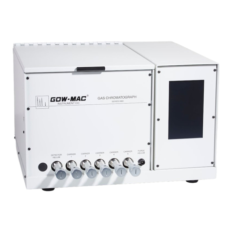
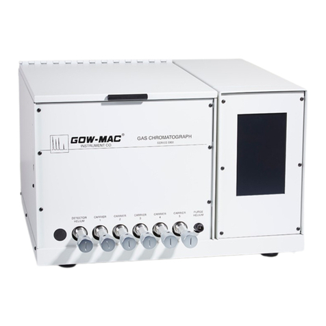
Gow-Mac 580 series User manual

Operating Manual
Series 580 TCD Isothermal
Gas Chromatograph
Series 580: 120 V, 50/60 Hz
Series 582: 230 V, 50/60 Hz
September 2017
Rev. 5
READ INSTRUCTIONS
BEFORE OPERATING
277 Brodhead Rd., Bethlehem, PA 18017-8600 U.S.A. Tel: (610) 954-9000

GOW-MAC Instrument Co.2

Series 580 TCD Gas Chromatograph
September 2017, Rev. 5
3
DISCLAIMERS
The information in this document is subject to change without notice. This manual could include technical inaccuracies or
typographical errors. Changes are made periodically to the information herein; these changes will be incorporated in subsequent
revisions of the manual. GOW-MAC® Instrument Co. reserves the right to make improvements and/or changes to the product(s)
and/or programs described in this manual at any time and without notice.
All information referred to and/or included in this report is current as of the original issue date of this manual. GOW-MAC®
Instrument Co. makes no warranty or representation with respect to the accuracy of the information or with respect to the
suitability of the use of such information outside GOW-MAC® Instrument Co., nor does GOW-MAC® Instrument Co. assume
responsibility for any injury or damage which may result, directly or indirectly, from the use of such information.
This document contains proprietary information which is protected by copyright. All rights are reserved. No part of the document
may be photographed, reproduced, or translated into another language without the prior written consent of GOW-MAC®
Instrument Co.
The warranties made by GOW-MAC® Instrument Co. with respect to the product are voided if the product is not used and
serviced in accordance with the instructions in this manual.
Please protect yourself and your employees by following these operating instructions. We encourage our customers to write
or call for any additional information relative to the use or repair of this instrument.
TRADEMARK AND PATENT INFORMATION
®GOW-MAC is a registered trademark of GOW-MAC Instrument Co.
in the United States and other countries. (Reg. U.S. Pat. & T. M. offi ce)
Other trademarks used herein are trademarks or registered trademarks of their respective owners.
Copyright© 2011 by GOW-MAC® Instrument Co.

GOW-MAC Instrument Co.4
TERMS AND CONDITIONS OF SALE
WARRANTIES THE INSTRUMENTS SOLD BY GOW-MAC® INSTRUMENT CO. ARE WARRANTED FOR A PERIOD OF
ONE YEAR AGAINST DEFECTS IN MATERIALS AND WORKMANSHIP. THE TERMS OF THIS WARRANTY ARE AS FOLLOWS:
1. The warranty period begins with the shipping date of the equipment to the original purchaser.
2. Certain parts such as batteries, fuses, lamps, fi laments, columns, etc., are expendable in normal use, and their service life is
unpredictable. Such items are not covered by this warranty.
3. All requests for service or repair under this warranty must be received within the warranty period by GOW-MAC® or its authorized
representative. All repairs are made at GOW-MAC plants or at the offi ce of authorized representatives.
4. All repairs, adjustments, and other service under this warranty shall be performed free of charge to the purchaser. However,
warranty service and repairs shall be limited to equipment malfunctions which, in the opinion of GOW-MAC®, are due or
traceable to defects in original materials or workmanship. Instrument malfunctions caused by abuse or neglect of the equipment
are expressly not covered by this warranty.
5. Instrument parts which have been repaired or replaced during the warranty period are themselves warranted only for the
remaining unexpired portion of the original one year warranty.
6. Repairs, adjustments, and service performed after expiration of the one year warranty period shall be charged to the purchaser
at the then current prices for parts, labor, and transportation.
7. This warranty attaches to the equipment itself and is not limited to the original purchaser. Unexpired portions of the warranty
are thus transferable to subsequent owners.
8. GOW-MAC® expressly disclaims any liability to users of its products for consequential damages of any kind arising out of or
connected with the use of its products.
9. Except as stated in Sections 1 through 8 above, GOW-MAC® makes no warranty, expressed or implied (either in fact or by
operation of law), statutory or otherwise; and, except as stated in Sections 1 through 8 above, GOW-MAC® shall have no
liability under any warranty, expressed or implied (either in fact or by operation of law), statutory or otherwise.
10. Statements made by any person, including representatives of GOW-MAC® which are inconsistent or in confl ict with the terms
of this warranty shall not be binding upon GOW-MAC® unless reduced to writing and approved by an offi cer of the Company.
11. This warranty shall be governed by the laws of the Commonwealth of Pennsylvania.
LIABILITY Buyer assumes all responsibility for warning and protecting its employees and independent contractors with respect to
all hazards to persons and property in any way connected with the Equipment and the use thereof. Seller’s liability for any claim of any
kind hereunder, whether or not based on contract, tort (including negligence), strict liability, warranty, or any other grounds, shall not
exceed the purchase price of the Equipment or the portion of the purchase price attributable to any part or parts of the Equipment in
respect to which such claim is made. Seller shall not be liable for any special, indirect, incidental, or consequential damages. Without
limiting the generality of the foregoing, Seller shall have no liability with respect to the results obtained by use of the Equipment,
whether in terms of product condition, operating cost, general eff ectiveness, success or failure, or regardless of any statement made
in any written proposal submitted by Seller. It is expressly understood that any technical advice furnished by Seller with reference
to the Equipment is given gratis and Seller assumes no obligation or liability for the advice given or results obtained, all such advice
being given and accepted at Buyer’s risk. Each party hereby agrees to indemnify and hold the other party harmless from any actions,
lawsuits, demands, claims, losses, expenses, costs, including but not limited to legal fees, and damages arising from the injury, illness
or death of the indemnifying party’s employees in any way related to the Equipment, whether or not such injury, illness, or death is
claimed to have been caused by, resulted from, or was in any way connected with the negligence of the party to be indemnifi ed.
PROPRIETARY INFORMATION Buyer agrees to maintain all proprietary information disclosed by Seller, including such
proprietary information obtainable upon examination of the Equipment, in confi dence and to refrain from any disclosure thereof to
any third party (including any affi liate of Buyer), for any purpose, without the prior written consent of Seller. Buyer agrees to use said
proprietary information solely for purposes of maintaining and operating the Equipment, and to refrain from any use thereof to design,
construct, have constructed and/or operate any duplication or modifi cation of the Equipment, or from any other use thereof, without
the prior written consent of Seller.

Series 580 TCD Gas Chromatograph
September 2017, Rev. 5
5
IMPORTANT INFORMATION
These instructions are written for personnel operating the GOW-MAC® Series 580 TCD Gas
Chromatograph. Read and understand the safety precautions in this manual to become familiar with
the safe practices for operating this equipment.
Dangers, Warnings, Cautions, and Notes
Dangers, Warnings, Cautions, and Notes appear throughout this manual. A sample of each statement
appears below. Within each sample, a defi nition of the statement type and its purpose is given.
DANGER
!
DANGERS alert you to an immediate hazard that causes serious injury or
death and requires special precautions to be taken.
WARNING
!
WARNINGS alert you to a potential hazard that causes serious injury or
death under certain conditions.
CAUTION
CAUTIONS alert you to a non-immediate or potential hazard or an unsafe
practice that presents a minor threat of personal injury or damage to
equipment, data, or processes.
NOTE
&
NOTES emphasize or remind you of an important piece of information.

GOW-MAC Instrument Co.6

Series 580 TCD Gas Chromatograph
September 2017, Rev. 5
7
Contents
Section 1 Specifi cations ...................................................................................... 13
Section 2 Safety ..................................................................................................... 15
Section 3 Installation ............................................................................................. 17
Section 4 Operating Controls ............................................................................... 25
Section 5 Operation ............................................................................................... 29
Section 6 Valves .................................................................................................... 37
Section 7 Maintenance .......................................................................................... 43
Section 8 Options & Accessories ........................................................................ 51
Section 9 Troubleshooting ................................................................................... 55
Section 10 Replacement Parts ............................................................................... 63
Section 11 Drawings & Schematics ....................................................................... 65

GOW-MAC Instrument Co.8

Series 580 TCD Gas Chromatograph
September 2017, Rev. 5
9
Series 580 Thermal Conductivity Isothermal Gas Chromatograph
Operation & Maintenance Manual
This manual provides operating instructions and maintenance requirements for the Series 580 GC
to permit safe and effi cient use of your instrument. Throughout this manual, special “NOTE”,
“CAUTION”, and “WARNING” signs appear for your protection. It is important that you thoroughly
read the appropriate sections of this manual before operating your instrument. Certain sections of
this manual apply to specifi c options you may have chosen for your instrument. The information
contained within concerns itself with a standard hotwire detector GC. If you have Options 204 or
218 (Capillary) installed, make sure to read Section 8. Operate the Series 580 GC according to
these instructions. Any questions concerning the safe and proper use of your instrument should
be addressed to:
GOW-MAC INSTRUMENT CO.
277 Brodhead Road,
Bethlehem, PA 18017-8600
TEL: (610) 954-9000
FAX: (610) 954-0599
E-mail: [email protected]

GOW-MAC Instrument Co.10

Series 580 TCD Gas Chromatograph
September 2017, Rev. 5
11
IMPORTANT!
Your new Series 580 TCD Isothermal Gas Chromatograph contains one of the following detector/
fi lament confi gurations:
_____ Single Carrier TCD _____ Dual Carrier TCD
with _____ WX (rhenium-tungsten)
_____ WXB (rhenium-tungsten, inverted header – dual carrier TCD only)
_____ W2B (tungsten, inverted header – dual carrier TCD only)
_____ W2X (rhenium-tungsten, dual helix)
_____ AuW (gold sheathed tungsten)
_____ Ni (nickel)
_____ WX7 (low current, high sensitivity rhenium-tungsten)
FOLLOW THE PRESCRIBED BRIDGE CURRENTS AND CELL TEMPERATURES FOR
YOUR PARTICULAR DETECTOR AND SET OF FILAMENTS (REFER TO CHARTS 5-1 thru 5-5
IN THIS MANUAL). FAILURE TO REMAIN WITHIN THE STATED LIMITS WILL CAUSE
FILAMENT BURN OUT.
RECOMMENDED STARTING BRIDGE SETTINGS FOR HELIUM
WX fi laments ..........................100 mA
AuW fi laments ..........................100 mA
Ni fi laments ..........................100 mA
WX7 fi laments .......................... 80 mA
FILAMENT OPERATING NOTES
1. Filament life may be extended by operating at low current and low cell temperatures. The
cell temperature should only be as high as needed for samples used, and current should
be as low as possible consistent with sensitivity required. It is better to operate the system
at an attenuation of 1x or 2x at low bridge currents than at higher currents with higher
attenuation.
2. Sensitivity increases 4 to 8 times as fi lament current increases by a factor of 2. However,
increasing fi lament current excessively results in baseline instability and possible fi lament
burnout. Care must be observed in arbitrarily changing bridge current.

GOW-MAC Instrument Co.12
If your instrument was engineered to analyze corrosive samples (usually designated by a
“-CR” in the part number), take note:
CAUTION CAUTION!
This instrument was designed for DRY sample applications only!
Care must be taken to make sure only moisture-free samples are
introduced into the system.
GOW-MAC® Instrument Company is not responsible for damage to
equipment caused by exposure to hydrolyzed samples.

Series 580 TCD Gas Chromatograph
September 2017, Rev. 5
13
Section 1
Specifi cations
(dependent upon the number of options ordered)
OVERALL:
H 12 1/2” (317 mm)
W 19 1/2” (495 mm) width varies due to housing used for options ordered
D 18” (457 mm)
Net Weight: 70 lbs. (31.75 kg) Shipping: 80 lbs. (36.21 kg)
POWER REQUIREMENTS:
Series 580: 105 - 125 Vac, 50/60 Hz, 1100 W
Series 582: 200 - 240 Vac, 50 Hz, 1100 W
Fuse: Series 580: 10 Amps
Series 582: 5 Amps
COLUMN OVEN:
H 7 1/2” (190 mm)
W 10” (254 mm)
D 8 1/2” (216 mm)
Temperature Range: ambient to 400 °C
Temperature Readout: 3 1/2 digit LED digital meter Temperature Control: solid state, time
proportioning, RTD sensors, direct reading, ambient to 400 °C
Column Oven Temperature Protection Circuit: shuts the column oven off if the temperature
rises to 30 °C over the set point. Oven Fittings: accommodates 1/8” or 1/4” o.d. metal,
6 mm glass, or capillary columns.
Oven Capacity: can accommodate up to two (2) 1/4” o.d. x 20’ columns or correspondingly
longer lengths of 1/8” o.d.
DETECTOR OVEN:
Temperature Settings: ambient to 400 °C
Temperature Readout: 3 1/2 digit LED digital meter
Temperature Control: solid state time proportioning, RTD sensors, direct reading, ambient
to 400 °C

GOW-MAC Instrument Co.14
DETECTOR:
Detector Type: thermal conductivity
Design: fl ow-through
Detector Elements: four (4) Rhenium-tungsten (WX), gold-sheathed tungsten (AuW);
nickel (Ni); or high sensitivity rhenium tungsten (WX7) on standard 9225 mount;
tube nut closure.
Response Time: 0.5 sec.
Noise: 10 V max. within operating parameters
Drift: 40 V/hour max.
Carrier Gas: N2, He, H2, or Argon
Current Limit: 300 mA with H2 [Reference recommended starting settings,
120 mA with N2 Section 5, 2B.b, pgs. 29-32]
INJECTION PORTS:
Septum: standard 9 mm
Temperature Control: solid state, time proportioning, RTD sensors, direct reading,
ambient to 400 °C.
Temperature Readout: 0 - 400 °C, 3 1/2 digit LED digital meter
Injection Method: direct on-column or gas sample valves
GAS FLOW (conditions may vary depending upon the options chosen for your instrument)
Dual-column with dual injection ports and exits.
Two metering valves for separate control of each column.
Exit ports allow easy collection of effl uent.
Filament protector pressure switch in carrier inlet line.
THERMAL CONDUCTIVITY BRIDGE CONTROL
Continuous current adjust, 0 - 300 mA
Bridge zero adjust
Attenuator for bridge output, 12 positions to 1024 plus infi nity ()
Polarity Switch
POWER SUPPLY
Line operated, solid state, integrated circuit regulated, constant current
55 Vdc (max.), 300 mA (max.)
Ripple and noise less than 5 V
x10 SIGNAL AMPLIFIER (OPTIONAL): amplifi es the detector signal by a factor of 10 for
enhanced sensitivity.

Series 580 TCD Gas Chromatograph
September 2017, Rev. 5
15
Section 2
Safety
This section is designed to bring special attention to specifi c areas or practices that may pose
particular hazards to personnel and/or equipment safety only. For complete installation instructions,
see Section 3.
It is in the operator’s best interest to read this section to ensure the safe operation of the equipment.
A. BURN HAZARDS
The injection ports, columns, and column oven cover may reach very high temperatures, and
remain hot for several hours after the instrument has been shutdown. To prevent painful burns
resulting from contact with the hot surfaces, wear protective gloves.
B. ELECTRICAL HAZARDS
1. DISCONNECT the instrument from all power sources before removing front, side, and back
panels and exposing potentially dangerous voltages.
2. Make sure that the actual line voltage is the value for which the instrument was designed.
(for properly grounded outlet ONLY.)
3. DO NOT overload the ac outlet with other electrical equipment.
4. Adhere to the color coding descriptions when hooking up electrical connections.
5. Repair or replace faulty or frayed wiring.
C. COMPRESSED GAS CYLINDERS
Compressed gas cylinders are potential sources of serious accidents, injuries, and even death if
proper precautions and safety practices are not followed. Therefore, during handling and use of
these gases, be certain to use applicable safety precautions described by your compressed gas
supplier, the Compressed Gas Association, and/or O.S.H.A. regulations.
1. Read the label on all cylinders BEFORE using to identify the cylinder contents. If the label is
illegible, return the cylinder to the supplier. DO NOT ASSUME THE CONTENTS.
2. All gas cylinders in use and in storage MUST be properly secured to an immovable structure
to prevent accidental falling or movement. Read all relevant safety codes.
3. Store or move cylinders ONLY in the vertical position.
4. DO NOT move or transport cylinders with regulators attached or without safety cap secured
over the valve system.
5. Store cylinders in a well ventilated area away from heat or ignition sources.

GOW-MAC Instrument Co.16
6. When installing tubing, provide ONLY proper pressure reducing regulators and
pressure relief devices to prevent overpressure of tubing and equipment.
D. GENERAL
1. Perform periodic leak checks on all fi ttings.
2. Store organic solvents away from the GC in fi reproof, vented, labelled cabinets.
3. DO NOT allow fl ammable and/or toxic wastes to accumulate.
4. Keep combustibles away from gas cylinders and eliminate ignition sources.
5. DO NOT place papers, charts, samples, etc. on top of the GC.
6. Maintain adequate ventilation.
7. Dispose of wastes properly.

Series 580 TCD Gas Chromatograph
September 2017, Rev. 5
17
Section 3
Installation
A. General
The customer should read and become familiar with this section before proceeding with the
installation of the Series 580 GC.
B. Additional Equipment Required
1. Carrier Gas Cylinder: cylinder should be equipped with a two-stage quality regulator for
control of the carrier gas. The fi rst gauge indicates the tank pressure and the second
(adjustable) gauge indicates the delivery pressure to the chromatograph, (0-75 psig).
2. Potentiometric recorder with 1 mV span, 1 sec. response, or 10 mV span. mV INPUT
MUST NOT BE GROUNDED. A computing integrator or chromatography software may
also be used.
3. Stopwatch and a 10 mL soap bubble fl owmeter for gas fl ow measurements. A “rotameter” or
digital fl owmeter may be used for direct reading if it is properly calibrated.
4. AC power source: Series 580: 1100 W at 115 V, 60 Hz
Series 582: 550 W at 230 V, 50 Hz
CAUTION
OPERATING INSTRUCTIONS FOR BOTH MODELS ARE THE SAME,
EXCEPT FOR LINE VOLTAGE REQUIREMENTS. TO PREVENT
DAMAGE TO THE INSTRUMENT, MAKE SURE THAT THE AC
ELECTRICAL OUTLET IS THE CORRECT VOLTAGE FOR YOUR
INSTRUMENT BEFORE PLUGGING IT INTO THE OUTLET.
5. GOW-MAC Installation Kit (Part no. 59-400) or 1/8” o.d. copper tubing and Swagelok®
fi ttings.
6. Columns suitable to your application.
C. Unpacking-Inspection
1. When unpacking the instrument, check it carefully for evidence of shipping damage or rough
handling. Check to ensure that all components ordered have either been supplied or
back-ordered. Notify the Company of any discrepancies. The packing box should be retained
for use if the instrument needs to be returned to the factory for repair or modifi cation.
GOW-MAC does not supply fi eld service. ALL repairs are made at Bethlehem, Pennsylvania
USA or by an authorized representative.
2. Remove all plastic and/or paper shipping caps and restraints before operating.
Swagelok® - trademark of Crawford Fitting Co.

GOW-MAC Instrument Co.18
3. Fill out and mail the yellow WARRANTY-REGISTRATION CARD (included with this manual)
to ensure that the warranty will be validated and that you will be kept informed of any
improvements or other items of interest.
D. Location
1. The Series 580 GC should be placed in a location that is secure, vibration-free, protected
from abrupt temperature changes (maximum ambient temperature range is 15 °C to 40 °C),
and drafts. Such changes may upset the temperature stability in the course of an analysis or
preparation.
2. Enough adjacent tabletop space should be allowed for the installation of recorders,
integrators, computers, etc. Allow suffi cient space on all sides of the Series 580 GC for easy
access.
3. Make sure there is adequate space for the installation of the carrier gas cylinder. Cylinders
should be securely fastened to the wall or table.
CAUTION READ “SECTION 2 - SAFETY” TO ENSURE PROPER HANDLING
OF GAS CYLINDERS.
4. An electrical outlet (ac) should be near the location where the Series 580 GC is to be
installed. If the outlet is not a 3-pin type, make sure that a good ground connection is
available, since a good ground is necessary for proper operation. The ac outlet should be
connected to a circuit that is not heavily loaded with other electrical equipment because input
voltage to the instrument should be steady for optimum operating stability.
If the ac line voltage varies, consideration should be given to the installation of a stabilizing
transformer at the ac outlet.
NOTE
)
Both recorder and the Series 580 GC should be connected to the
same duplex service outlet to prevent ground loops.
E. Power Requirements
The Series 580 GC requires a 115 volt/60 Hz power source capable of providing up to 10 amps.
The Series 582 GC requires a 230 volt/50 Hz power source capable of providing up to 5 amps.
The ac power cord is terminated with a straight-blade 3-prong plug rated for 15 amp service that
requires a matching receptacle.
CAUTION MAKE SURE ALL SWITCHES ON FRONT AND BACK OF THE
SERIES 580 GC ARE IN THE “OFF” POSITION BEFORE PLUGGING
IN THE INSTRUMENT.

Series 580 TCD Gas Chromatograph
September 2017, Rev. 5
19
F. Recorder Connection
Supplied with your G.C. is a recorder cable. Both ends of the cable terminate in three spade
terminals.
Cable color code is as follows: Red lead, positive (+); black lead, negative (-), silver (shielded)
lead, ground.
1. Connect one end of the recorder cable to the terminals located at the rear of the G.C.
(Figure 3-1). Connection should be made as follows:
Black to black
Red to red
Silver to green
2. Connect the other end of the recorder cable to the proper terminals on the recorder.
GND
-+
INLET
RECORDER
GND
-+
I
O
Figure 3-1
Recorder Cable Connection
G. Integrator Connection
The same cable referred to above can be used for connecting an integrator to the GC.
H. Chromatography Data handling Software
The Series 580 TCD GC may also be used with a chromatography data handling software for full
data acquisition.

GOW-MAC Instrument Co.20
I. Gas Connections
CAUTION READ “SECTION 2-SAFETY” BEFORE CONTINUING. O.S.H.A.
REGULATION FOR THE HANDLING, STORAGE, AND USE
OF COMPRESSED GAS CYLINDERS REFERS TO THE
REQUIREMENTS OF THE COMPRESSED GAS ASSOCIATION.
1. A 1/8” o.d. stainless steel tube extends from the back of the G.C. (Figure 3-2). This is the
CARRIER GAS INLET.
GND
-+
INLET
Carrier Gas
I
O
Figure 3-2
Carrier Gas Connection
2. Either using the GOW-MAC Installation Kit (Part No. 59-400) or fi ttings and copper tubing of
your own, connect a 1/8” o.d. piece of clean copper tubing* from the gas outlet located on
the regulator of the carrier gas cylinder to the CARRIER GAS INLET on the back of the GC
(Swagelok® fi ttings are recommended).
NOTE
)
PLASTIC TUBING IS NOT RECOMMENDED, SINCE ALL PLASTICS
ARE PERMEABLE TO AIR.
* To prevent contamination of your GC by grease, oil, or chemical residue, the following
procedure should be followed for purging additional stainless steel or copper tubing
PRIOR to connecting it to the Series 580.
a. Clean tubing by fl ushing with acetone, to remove any oil residue that may be present.
b. After washing, let tubing drain and dry.
3. All lines and tubing should be clean and free from moisture.
Other manuals for 580 series
1
This manual suits for next models
1
Table of contents
Other Gow-Mac Laboratory Equipment manuals
Popular Laboratory Equipment manuals by other brands

Ametek
Ametek TAYLOR HOBSON TALYROND 500 PRO Operator's guide

Thermo Scientific
Thermo Scientific Heraeus Multifuge 4KR instruction manual

Kubota
Kubota 2420 Nstruction and service manual

HHP
HHP Imageteam 3800LTP quick start guide

Bego
Bego Miditherm 200 MP Translation of the original instructions

Ultimaker
Ultimaker S7 Installation and user manual