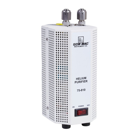
Gow-Mac 400 Series User manual

Operating Manual
Series 400/402 & 400-P/402-P
Thermal Conductivity
Gas Chromatograph
Series 400: 120 V, 50/60 Hz
Series 402: 230 V, 50/60 Hz
May 2017
Rev. 7
READ INSTRUCTIONS
BEFORE OPERATING
PO Box 25444, Lehigh Valley, PA 18002-5444 U.S.A. Tel: (610) 954-9000

GOW-MAC Instrument Co. Series 400 / 402 Gas Chromatograph Operating Manual
May 2017, Rev. 7
2

3
Series 400 / 402 Gas Chromatograph Operating Manual GOW-MAC Instrument Co.
May 2017, Rev. 7
Contents
Disclaimers ........................................................................................................................... 5
Important Information ........................................................................................................... 6
Warranty ................................................................................................................................ 7
Important Warning ................................................................................................................ 9
Important: Gas Flow Adjustment Note ................................................................................ 10
Chapter 1 - Safety Precautions ............................................................................................11
Chapter 2 - Specifi cations ................................................................................................... 13
Chapter 3 - Installation ........................................................................................................ 15
Chapter 4 - Operation .......................................................................................................... 23
Chapter 5 - Microscale Prep ................................................................................................ 31
Chapter 6 - Valves ............................................................................................................... 35
Chapter 7 - Software ........................................................................................................... 39
Chapter 8 - Experimental Run Through ............................................................................... 41
Chapter 9 - Maintenance ..................................................................................................... 47
Chapter 10 - Replacement Parts ......................................................................................... 53
Chapter 11 - Mechanical Drawings ..................................................................................... 55

GOW-MAC Instrument Co. Series 400 / 402 Gas Chromatograph Operating Manual
May 2017, Rev. 7
4

5
Series 400 / 402 Gas Chromatograph Operating Manual GOW-MAC Instrument Co.
May 2017, Rev. 7
DISCLAIMERS
The information in this document is subject to change without notice. This manual could include technical inaccuracies
or typographical errors. Changes are made periodically to the information herein; these changes will be incorporated
in subsequent revisions of the manual. GOW-MAC® Instrument Co. reserves the right to make improvements and/or
changes to the product(s) and/or programs described in this manual at any time and without notice.
All information referred to and/or included in this report is current as of the original issue date of this manual. GOW-
MAC® Instrument Co. makes no warranty or representation with respect to the accuracy of the information or with
respect to the suitability of the use of such information outside GOW-MAC® Instrument Co., nor does GOW-MAC®
Instrument Co. assume responsibility for any injury or damage which may result, directly or indirectly, from the use
of such information.
This document contains proprietary information which is protected by copyright. All rights are reserved. No part of the
document may be photographed, reproduced, or translated into another language without the prior written consent of GOW-
MAC® Instrument Co.
The warranties made by GOW-MAC® Instrument Co. with respect to the product are voided if the product is not used and
serviced in accordance with the instructions in this manual.
Please protect yourself and your employees by following these operating instructions. We encourage our customers to write
or call for any additional information relative to the use or repair of this instrument.
TRADEMARK AND PATENT INFORMATION
®GOW-MAC is a registered trademark of GOW-MAC Instrument Co.
in the United States and other countries.
Other trademarks used herein are trademarks or registered trademarks of their respective owners.
Swagelok® - is a registered trademark of Crawford Fitting Co.
Parker® - is a registered trademark of Parker Hannifi n Corp.
Gyrolok® - is a registered trademark of Hoke, Inc.
Copyright© 2005-2015 by GOW-MAC® Instrument Co.

GOW-MAC Instrument Co. Series 400 / 402 Gas Chromatograph Operating Manual
May 2017, Rev. 7
6
LIABILITY Buyer assumes all responsibility for warning and protecting its employees and independent contractors with respect
to all hazards to persons and property in any way connected with the Equipment and the use thereof. Seller’s liability for any claim
of any kind hereunder, whether or not based on contract, tort (including negligence), strict liability, warranty, or any other grounds,
shall not exceed the purchase price of the Equipment or the portion of the purchase price attributable to any part or parts of the
Equipment in respect to which such claim is made. Seller shall not be liable for any special, indirect, incidental, or consequential
damages. Without limiting the generality of the foregoing, Seller shall have no liability with respect to the results obtained by use
of the Equipment, whether in terms of product condition, operating cost, general eff ectiveness, success or failure, or regardless of
any statement made in any written proposal submitted by Seller. It is expressly understood that any technical advice furnished by
Seller with reference to the Equipment is given gratis and Seller assumes no obligation or liability for the advice given or results
obtained, all such advice being given and accepted at Buyer’s risk. Each party hereby agrees to indemnify and hold the other party
harmless from any actions, lawsuits, demands, claims, losses, expenses, costs, including but not limited to legal fees, and damages
arising from the injury, illness or death of the indemnifying party’s employees in any way related to the Equipment, whether or not
such injury, illness, or death is claimed to have been caused by, resulted from, or was in any way connected with the negligence
of the party to be indemnifi ed.
PROPRIETARY INFORMATION Buyer agrees to maintain all proprietary information disclosed by Seller, including such
proprietary information obtainable upon examination of the Equipment, in confi dence and to refrain from any disclosure thereof to
any third party (including any affi liate of Buyer), for any purpose, without the prior written consent of Seller. Buyer agrees to use
said proprietary information solely for purposes of maintaining and operating the Equipment, and to refrain from any use thereof to
design, construct, have constructed and/or operate any duplication or modifi cation of the Equipment, or from any other use thereof,
without the prior written consent of Seller.
IMPORTANT INFORMATION
These instructions are written for personnel operating the GOW-MAC® Series 400 Isothermal TCD Gas
Chromatograph. Read and understand the safety precautions in this manual to become familiar with the safe
practices for operating this equipment.
Dangers, Warnings, Cautions, and Notes
Dangers, Warnings, Cautions, and Notes appear throughout this manual. A sample of each statement
appears below. Within each sample, a defi nition of the statement type and its purpose is given.
DANGER
!
DANGERS alert you to an immediate hazard that causes serious injury or death
and requires special precautions to be taken.
WARNING
! WARNINGS alert you to a potential hazard that causes serious injury or death
under certain conditions.
CAUTION
CAUTIONS alert you to a non-immediate or potential hazard or an unsafe
practice that presents a minor threat of personal injury or damage to
equipment, data, or processes.
NOTE
&
NOTES emphasize or remind you of an important piece of information.

7
Series 400 / 402 Gas Chromatograph Operating Manual GOW-MAC Instrument Co.
May 2017, Rev. 7
Warranty
THE SERIES 400 TCD GC SOLD BY GOW-MAC® INSTRUMENT CO. IS WARRANTED FOR A PERIOD
OF ONE (1) YEAR AGAINST DEFECTS IN MATERIALS AND WORKMANSHIP. THE TERMS OF THIS
WARRANTY ARE AS FOLLOWS:
1. The warranty period begins with the shipping date of the equipment to the original purchaser.
2. Certain parts such as septa, batteries, fuses, glass accessories, detectors, fi laments, columns, etc., are
expendable in normal use, and their service life is unpredictable. Such items are not covered by this warranty.
3. All requests for service or repair under this warranty must be received within the warranty period by
GOW-MAC® or its authorized representative. All repairs are made at GOW-MAC plants or at the offi ce of
authorized representatives.
4. All repairs, adjustments, and other service under this warranty shall be performed free of charge to the
purchaser. However, warranty service and repairs shall be limited to equipment malfunctions which, in the
opinion of GOW-MAC®, are due or traceable to defects in original materials or workmanship. Instrument
malfunctions caused by abuse or neglect of the equipment are expressly not covered by this warranty.
5. Instrument parts which have been repaired or replaced during the warranty period are themselves warranted
only for the remaining unexpired portion of the original six month warranty.
6. Repairs, adjustments, and service performed after expiration of the six month warranty period shall be
charged to the purchaser at the then current prices for parts, labor, and transportation.
7. This warranty attaches to the equipment itself and is not limited to the original purchaser. Unexpired portions
of the warranty are thus transferable to subsequent owners.
8. GOW-MAC® expressly disclaims any liability to users of its products for consequential damages of any
kind arising out of or connected with the use of its products.
9. Except as stated in Sections 1 through 8 above, GOW-MAC® makes no warranty, expressed or implied
(either in fact or by operation of law), statutory or otherwise; and, except as stated in Sections 1 through 8
above, GOW-MAC® shall have no liability under any warranty, expressed or implied (either in fact or by
operation of law), statutory or otherwise.
10. Statements made by any person, including representatives of GOW-MAC® which are inconsistent or in
confl ict with the terms of this warranty shall not be binding upon GOW-MAC® unless reduced to writing
and approved by an offi cer of the Company.
11. This warranty shall be governed by the laws of the Commonwealth of Pennsylvania.

GOW-MAC Instrument Co. Series 400 / 402 Gas Chromatograph Operating Manual
May 2017, Rev. 7
8

9
Series 400 / 402 Gas Chromatograph Operating Manual GOW-MAC Instrument Co.
May 2017, Rev. 7
IMPORTANT WARNING
THIS MANUAL MUST BE CAREFULLY READ BY ALL INDIVIDUALS WHO HAVE OR WILL HAVE
THE RESPONSIBILITY FOR INSTALLING, USING, OR SERVICING THE PRODUCT.
Like any piece of complex equipment, the SERIES 400 ISOTHERMAL TCD GAS CHROMATOGRAPH
will perform as designed only if it is installed, used and serviced in accordance with the
manufacturer’s instructions. OTHERWISE IT COULD FAIL TO PERFORM AS DESIGNED AND
PERSONS WHO RELY ON THIS PRODUCT FOR THEIR SAFETY COULD SUSTAIN SEVERE
BODILY INJURY OR DEATH.
The warranties made by GOW-MAC Instrument Co. with respect to the product are voided if the product
is not installed, used and serviced in accordance with the instructions in this manual.
Please protect yourself and your employees by following these operating instructions. We encourage
our customers to write or call for any additional information relative to the use or repair of this
instrument.
Technical Support
GOW-MAC Instrument Co.
277 Brodhead Road
Bethlehem, PA 18017 U.S.A.
Tel: (610) 954-9000
Fax: (610) 954-0599
E-mail: [email protected]

GOW-MAC Instrument Co. Series 400 / 402 Gas Chromatograph Operating Manual
May 2017, Rev. 7
10
IMPORTANT
Gas Flow Adjustment Notes
1. Carrier pressure required varies with the length and packing material of the installed
columns Pressure must be at least 15 psig to close the pressure switch and energize the
detector current. Thirty (30) psig is adequate for most columns.
2. Before reading measurement, allow fi ve (5) minutes for the rate to equilibrate after each
adjustment.
3. Inert carrier gas MUST be fl owing through both columns A and B as well as sides A & B
of the TC detector at all times. THIS IS EXTREMELY IMPORTANT and NECESSARY to
preserve the fi laments!
Failure to set fl ow rates on both sides causes oxidation and destruction of the fi laments in
the presence of oxygen.

11
Series 400 / 402 Gas Chromatograph Operating Manual GOW-MAC Instrument Co.
May 2017, Rev. 7
Chapter 1 - Safety Precautions
1.1 This section is designed to bring special attention to specifi c areas or practices that may
pose particular hazards to personnel and/or equipment safety only. For complete installation
instructions, see Section 3.
It is in the operator’s best interest to read this sec tion to ensure the safe operation of the
instrument.
1.2 ELECTRICAL HAZARDS
A. This instrument employs voltages that are dangerous. EXTREME caution must be
exercised when working with this equipment. Disconnect the instrument from all power
sources before removing front, side or back panels and exposing potentially dangerous
voltages.
B. DO NOT handle exposed voltage terminations until the load and/or supply has been
discharged (grounded). An unloaded supply may take up to 15 seconds to fully discharge
after the instrument has been turned off and unplugged.
C. Make sure that the actual line voltage is the proper value for which the instrument was
designed. (For properly grounded outlet only).
D. DO NOT overload the ac outlet with other electrical equipment.
E. Adhere to the color coding descriptions when hooking up electrical connections.
F. Repair or replace faulty or frayed wiring IMMEDIATELY when it occurs.
1.3 COMPRESSED GAS CYLINDERS
Compressed gas cylinders are potential sources of serious accidents, injuries, and even death
if proper precautions and safety practices are not followed. Therefore, during handling and
use of these gases, be certain to use ap plicable safety precautions described by your local
compressed gas supplier, the Compressed Gas Association, and/or O.S.H.A. regulations.
A. Read the label on all cylinders BEFORE using to identify the cylinder contents. If the label is
illegible, return the cylinder to the supplier. DO NOT ASSUME THE CONTENTS.
B. Secure cylinders in storage and in use to an immovable structure to prevent accidental falling
or movement. Read the relevant safety codes.
C. Store or move cylinders ONLY in the vertical position and with cylinder caps installed. DO
NOT move or transport cylinders with regulators attached.
D. Store cylinders in a well ventilated area away from heat or ignition sources.
E. When installing tubing, provide ONLY approved, adequate pressure reducing regulators and
pressure relief devices to prevent over-pressurizing of tubing and equipment.

GOW-MAC Instrument Co. Series 400 / 402 Gas Chromatograph Operating Manual
May 2017, Rev. 7
12
F. Never drop cylinders or permit them to strike each other violently.
G. Cylinders may be stored in the open but, in such cases, should be protected against extremes
of weather and from damp ground (to prevent rusting). In areas where extreme temperatures
are prevalent, store cylinders in the shade.
H. The valve protection cap should be left on each cylinder until cylinder has been secured
against a wall or bench, or placed in a cylinder stand and is ready for use.
I. Avoid dragging, rolling or sliding cylinders even for a short distance. Move cylinders by using
a suitable hand truck.
J. Never tamper with safety devices in valves or cylinders.
K. Do not store full and empty cylinders together. Serious suck-back can occur when an empty
cylinder is attached to a pressurized system.
L. No part of a cylinder should be subjected to a temperature higher than 52 °C (125 °F).
Do not permit fl ame to come in contact with any part of a compressed gas cylinder.
and pressure relief devices to prevent over-pressurizing the tubing and equipment.
1.4 GENERAL
A. Perform periodic leak checks at all fi tting areas.
B. Store organic solvents away from the GC in fi reproof, vented, labeled cabinets.
C. DO NOT allow fl ammable and/or toxic wastes to accumulate.
D. Keep combustibles away from gas cylinders and elimi nate ignition sources.
E. DO NOT place papers, charts, samples, etc. on top of the GC.
F. Maintain adequate ventilation.
G. Dispose of wastes properly.

13
Series 400 / 402 Gas Chromatograph Operating Manual GOW-MAC Instrument Co.
May 2017, Rev. 7
Chapter 2 - Specifications
The Series 400/402 Gas Chromatograph is a rugged, compact, thermal conductivity GC designed
for high capability performance while withstanding rough, student or industrial use.
The fl ow system consists of two needle valves for accurate column fl ow control, dual injection ports,
dual columns and exits.
Temperature of injection ports, column oven and detector oven can be individually controlled. The
detector is housed in an easily accessible oven assembly. The thermal conductivity detector (TCD)
contains four 32 ohm, Rhenium-tungsten (WX) hotwire fi laments (standard).
The Series 400-P/402-P GC is equipped with a microscale preparative accessory system. This GC
is equipped with a microscale prep detector with outlet temperature control. The system is based on
the description given by Mayo, Pike, et. al., in Microscale Organic Laboratory, E. Wiley & Son,
N. Y., 1986.
Dimensions
Overall 16.50" H (410 mm) x 12.00" W (300 mm) x 11.00" D (270 mm)
Weight 27 lbs. (12.26 kg)
Power Requirements
Series 400: 110-120 VAC, 50/60 Hz: 600 W (max), 10 A circuit breaker
Series 402: 220-240 VAC, 50/60 Hz, 600 W (max), 4 A circuit breaker
Column Oven
Dimensions: 16.19 cm H x 25.40 cm W x 18.41 cm D
Volume: 7570.67 cm3 V
Temperature Range: Ambient to 400 °C
Temperature Control: solid state, time proportioning, RTD sensors, direct reading, ambient
to 400 °C
Temperature Readout: 3-1/2 digit LCD digital meter
Protection Circuit: shuts the column oven off if the temperature rises to 30 °C over set
point
Detector Outlet [optional with preparative detector (Series 400-P/402-P)]
Temperature Range: Ambient to 350 °C
Temperature Control: phase control, RTD sensor, ambient to 350 °C
Temperature Readout: 3-1/2 digit LCD digital meter
Operating Temperature: 20 °C above column temperature
Oven Fittings
Accommodates 1/8" or 1/4" o.d. metal or glass columns
Oven Capacity
Two 1/4" o.d. x 12' columns or correspondingly longer lengths of 1/8" o.d.

GOW-MAC Instrument Co. Series 400 / 402 Gas Chromatograph Operating Manual
May 2017, Rev. 7
14
Detector Oven
Temperature Range: Ambient to 400 °C
Temperature Control: solid state, time proportioning, RTD sensors, direct reading, ambient
to 400 °C
Temperature Readout: 3-1/2 digit LCD digital meter
Operating Temperature: 15 °C higher than the column temperature
Detector
Type: Thermal Conductivity (TCD)
Design: Flow-through
Elements: Four (4) Rhenium-tungsten (WX) on standard 9225 mount, tube nut
closure (standard unit)
Response Time: 0.5 seconds
Noise: 10 V maximum within operating parameters
Drift: 40 V hour maximum
Carrier Gas: Helium or Nitrogen
Max. Current Limit 100 mA with He Refer to the General Service Bulletin
at ambient temp: 120 mA with N2
Detector Power Supply
Line operated, solid state, integrated circuit regulated, constant current
55 Vdc (max.), 300 mA (max.)
Ripple and noise: < 5 mV rms
Injection Ports
Dual injection ports
Low Volume
Injection Method: direct on-column or gas sample valve injection
Septums: standard 9 mm
Operating Temperature: 0 - 400 °C
Temperature Control: solid state, time proportioning, RTD sensors, direct reading, ambient
to 400 °C
Temperature Readout: 3-1/2 digit LCD digital meter
Gas Flow
Flow System: dual column with dual injection ports and exits
Flow Control: two (2) metering valves for independent fl ow control to each column
Filament protector pressure switch in carrier inlet line.
Thermal Conductivity Bridge Control
Polarity Switch
Bridge Zero Adjust
Current Adjustment: continuous adjustment to 300 mA (using He carrier)
Attenuator: 12 positions to 1024 plus infi nity ()

15
Series 400 / 402 Gas Chromatograph Operating Manual GOW-MAC Instrument Co.
May 2017, Rev. 7
Chapter 3 - Installation
3.1 General
The customer should read and become familiar with this section before proceeding with
installation.
3.2 Additional Equipment Required
A. Carrier gas cylinder with standard pressure regulator, terminating in a 1/4" or 1/8" female
NPT fi tting.
B. Recording Device: a) Potentiometric recorder with 1 mV span, 1 second response; or b) a
computing integrator; or c) proper computer software.
C. Stopwatch and a 10 mL soap bubble fl owmeter (GM Part No. 59-230) for gas fl ow
measurements. A "rotameter" may be used for direct reading if it is properly calibrated
using a soap bubble fl owmeter. Also available is a hand-held digital bubble fl owmeter,
GOW-MAC Part No. 180-567 for automatic fl ow measurement.
D. AC power source: Series 400: 600 W at 110 - 130 V, 50/60 Hz
Series 402: 600 W at 220 - 240 V, 50/60 Hz
CAUTION
Operating instructions for bother series are the same, except
for line voltage requirements. To prevent damage to the
instrument, make sure that the AC electrical outlet is the
correct voltage for your instrument BEFORE plugging it into
the outlet.
E. GOW-MAC Installation Kit (Part No. 59-400) or 1/8" o.d. clean copper tubing and
Swagelok® fi ttings.
F. Columns suitable to your application. The Series 400 GC comes with one (1) 20%
Carbowax 20M column and one (1) 20% DC 200 column.
3.3 Unpacking-Inspection
A. When unpacking the instrument, check it carefully for evidence of shipping damage or
rough handling. Check to ensure that all components ordered have either been supplied
or back-ordered. Notify the Company of any discrepancies. The packing box should
be retained for use if the instrument needs to be returned to the factory for repair or
modifi cation. GOW-MAC does not supply fi eld service. All repairs are made at our
Bethlehem, PA facility or by an authorized GOW-MAC representative.

GOW-MAC Instrument Co. Series 400 / 402 Gas Chromatograph Operating Manual
May 2017, Rev. 7
16
B. Remove all plastic and/or paper shipping caps and restraints before operating.
C. Fill out and mail the WARRANTY-REGISTRATION card (included with this manual) to
ensure that the guarantee will be validated and that you will be kept informed of any
improvements or other items of interest.
3.4 Location
A. The Series 400 should be placed in a location that is secure, vibration-free, and protected
from abrupt temperature changes (maximum ambient temperature range is from 15 °C to
40 °C), and drafts. Such changes may upset the temperature stability in the course of an
analysis or preparation.
B. Enough adjacent tabletop space should be allowed for the installation of recorders,
integrators, computers, etc. Allow suffi cient space on all sides of the GC for easy access.
C. Make sure that there is adequate space for the installation of the carrier gas cylinder.
Cylinders should be securely fastened to the wall or table.
Read Chapter 1 - Safety Precautions to ensure proper
handling of compressed gas cylinders.
D. An electrical outlet (ac) should be near the location where the GC is to be installed. If the
outlet is not a 3-pin type, make sure that a good ground is available, since a good ground
is necessary for proper operation. The ac outlet should be connected to a circuit that is not
heavily loaded with other electrical equipment because input voltage to the instrument
should be steady for optimum operating stability.
If the ac line voltage varies, consideration should be given to the installation of a stabilizing
transformer at the ac outlet.
CAUTION
Both recorder and GC should be connected to the same
duplex service outlet to prevent ground loops.
3.5 Power Requirements
The Series 400 instrument requires a 50/60 Hz power source capable of providing up to
5 amps at 110-130 Vac.
The Series 402 instrument requires a 50/60 Hz power source capable of providing up to
3 amps at 210-230 Vac.
The ac power cord for the Series 400 is terminated with a straight-blade 3-prong plug rated for
10 amp service that requires a matching receptacle. A cord, with no plug, is supplied with the
Series 402 GC.

17
Series 400 / 402 Gas Chromatograph Operating Manual GOW-MAC Instrument Co.
May 2017, Rev. 7
3.6 Recorder Connection
Supplied with your GC is a recorder cable. Both ends of the recorder cable terminate in three
spade terminals.
Cable color is as follows: red lead = positive (+); black lead = negative (-); and silver (shielded)
lead = ground.
A. Connect one end of the recorder cable to the terminals located at the rear of the GC
(Figure 3-1). Connection should be made as follows:
Black to Black
Red to Red
Silver to Green
B. Connect the other end of the recorder cable to the proper terminals on the recorder.
-+
GND
Recorder
-+
GND
Figure 3-1
Series 400 GC and Recorder Connection
NOTE
&
While polarity is unimportant (because of the Polarity Switch),
the shielded ground wire should be connected to the proper
terminal on the recorder, if provided. Follow the recorder
manufacturer's instructions for grounding the recorder.

GOW-MAC Instrument Co. Series 400 / 402 Gas Chromatograph Operating Manual
May 2017, Rev. 7
18
3.7 Integrator Connection
The same cable referenced in the section above can be used for connecting the GC with an
integrator.
3.8 Software — make reference to Chapter 7.
3.9 Gas Connections
RE-READ CHAPTER 1 - SAFETY PRECAUTIONS BEFORE
CONTINUING. (O.S.H.A. REGULATION FOR THE HANDLING,
STORAGE, AND USE OF COMPRESSED GAS CYLINDERS
REFERS TO THE REQUIREMENTS OF THE COMPRESSED
GAS ASSOCIATION, CGA).
A. A 1/8" o.d. stainless steel tube extends from the rear of the GC (Figure 3-2). This is the
CARRIER GAS INLET.
B. Either using the GOW-MAC Installation Kit (Part No. 59-400) or fi ttings and clean copper
tubing of your own, connect a 1/8" o.d. piece of copper tubing from the gas outlet located
on the gas regulator of the gas cylinder to the CARRIER GAS INLET on the rear of the
GC. (Swagelok®, Parker®, or Gyrolok® fi ttings are recommended).
NOTE
&
Plastic tubing IS NOT recommended since all plastics are
permeable to air.
-+
GND
Carrier Gas
Inlet
C
A
R
R
I
E
R
G
A
S
Figure 3-2
Carrier Gas Hookup (Typical)

19
Series 400 / 402 Gas Chromatograph Operating Manual GOW-MAC Instrument Co.
May 2017, Rev. 7
C. To prevent contamination of your GC by grease, oil, or chemical residue, the following
procedure should be followed for purging additional stainless steel or copper tubing prior
to connecting it to the Series 400/402:
1. Clean tubing by fl ushing with acetone to remove any oil residue that may be present.
2. After washing, let tubing drain and dry.
3. Repeat Steps C-1 & C-2 three times.
WARNING
!
ACETONE IS EXTREMELY FLAMMABLE. USE CARE
WHEN USING THIS MATERIALS. DO NOT EXPOSE
ACETONE TO OPEN FLAMES OR SMOKING MATERIALS.
DISPOSE OF SOLVENT PROPERLY.
3.10 Leak Testing
All connections are thoroughly leak-tested prior to shipment from the factory.
A. Now that the carrier gas has been hooked up, set carrier gas fl ow to 30 mL/min through
BOTH columns A and B, which fl ows through BOTH sides of the detector. Perform the
following leak check procedure:
1. Open the hinged column oven cover.
2. Check all column connections (4) for tightness. The columns supplied are 1/4" o.d.
and the nuts (4) require a 9/16" open-end wrench.
3. Check septum nuts on front panel for tightness (fi nger tight).
4. Check the carrier gas connections at the back of the GC for tightness.
5. Check the fi ttings at the gas cylinder and copper tubing for tightness.
6. The column fl ow control valves are located on the front panel of the GC (Figure 4-5).
These should be closed gently (clockwise), then opened about 1/2 turn (counter
clockwise).
!
IMPORTANT
THESE ARE PRECISION NEEDLE VALVES, NOT SHUT-
OFF VALVES. CARE SHOULD BE EXERCISED IN MAKING
ADJUSTMENTS.
7. Using Tygon® tubing, connect the two OUTLET PORTS located on the side of the GC.
8. Adjust the PRESSURE REGULATOR on the cylinder to a gauge pressure of
approximately 30 psig, then shut off the gas at the cylinder.

GOW-MAC Instrument Co. Series 400 / 402 Gas Chromatograph Operating Manual
May 2017, Rev. 7
20
9. If the system is leak-free, the pressure gauge should remain at 30 psig. If the
pressure falls off within 15 to 20 minutes, there is a leak in the system.
10. The easiest way to locate leaks in the system is through the use of a GOW-MAC Gas
Leak Detector, Series 21-070. If one is not available, the use of a leak testing solution
(soap solution) and checking for bubbles may be used. Refer to Figure 3-3 to locate
possible leak areas.
NOTE
&
STEPS 7, 8, & 9 MAY BE OMITTED IF A GOW-MAC GAS LEAK
DETECTOR IS AVAILABLE.
Column "A" Column "B"
Metering Valves
for Columns A & B
Pressure Reduction
Valve
Pressure
Switch
Detector
H
e
l
I
u
m
Carrier Gas
Injection Port
for Column A
Injection Port
for Column B
Figure 3-3
!
IMPORTANT
LEAK CHECKS SHOULD BE RUN PERIODICALLY AND ARE
A MUST WHEN NEW COLUMNS OR CARRIER GAS FITTINGS
ARE INSTALLED.
11. Once leaks have been located and stopped, return the instrument to operating
condition; bleed all pressurized lines to atmospheric pressure, remove Tygon® tubing
at OUTLET PORTS.
This manual suits for next models
3
Table of contents
Other Gow-Mac Laboratory Equipment manuals