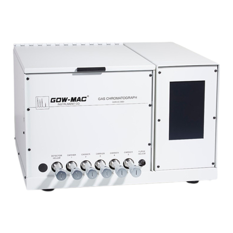
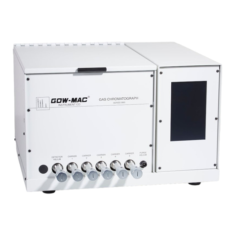
Gow-Mac 580 series User manual

Operating Manual
Series 580 FID Isothermal
Gas Chromatograph
Series 580: 120 V, 50/60 Hz
Series 582: 230 V, 50/60 Hz
March 2016
Rev. 8
READ INSTRUCTIONS
BEFORE OPERATING
PO Box 25444, Lehigh Valley, PA 18002-5444 U.S.A. Tel: (610) 954-9000


Contents
Section 1 Safety ............................................................................................................. 7
Section 2 Specifications................................................................................................ 9
Section 3 Installation....................................................................................................11
Section 4 Operating Controls ..................................................................................... 19
Section 5 Operation..................................................................................................... 23
Section 6 General Notes on FID Operation ............................................................... 29
Section 7 Maintenance & Service............................................................................... 31
Section 8 Valving.......................................................................................................... 35
Section 9 Capillary Chromatography......................................................................... 39
Section 10 Ruthenium Methanizer................................................................................ 43
MATERIAL SAFETY DATA SHEET.............................................................. 46
Section 11 Troubleshooting Chromatographic Interpretations* ............................... 53
Section 12 Replacement Parts...................................................................................... 61
Section 13 Drawings...................................................................................................... 63

GOW-MAC Instrument Co.
4

Series 580 FID Gas Chromatograph
March 2016 Rev. 8 5
Series 580 Flame Ionization Gas Chromatograph
Operation & Maintenance Manual
Thismanualprovidesoperatinginstructionsandmaintenancerequirementsfor the Series 580 FID GC to
permit safe and efficient use of your instrument. Throughout this manual, special “NOTE”, “CAUTION”,
“WARNING” signs appear for your protection. It is important that you thoroughly read the appropriate
sections of this manual before operating your instrument. Operate the SERIES 580 FID according to
these instructions. Any questions concerning the safe and proper use of your instrument should be
addressed to:
GOW-MAC Instrument Co.
277 Brodhead Road
Bethlehem, PA 18017
Tel: (610) 954-9000
Fax: (610) 954-0599
URL: www.gow-mac.com

GOW-MAC Instrument Co.
6

Series 580 FID Gas Chromatograph
March 2016 Rev. 8 7
Section 1
Safety
This section is designed to bring special attention to specific areas or practices that may pose
particularhazards to personnel and/orequipmentsafetyonly.Forcomplete installation instructions, see
Section 3.
It is in the operator’s best interest to read this section to ensure the safe operation of the equipment.
A. BURN HAZARDS
The injection ports, columns, and column oven cover may reach very high temperatures, and
remain hot for several hours after the instrument has been shutdown. To prevent painful burns
resulting from contact with the hot surfaces, wear protective gloves.
B. ELECTRICAL HAZARDS
1. DISCONNECT the instrument from all power sources before removing front, side, and back
panels and exposing potentially dangerous voltages.
2. Make sure that the actual line voltage is the value for which the instrument was designed.
(for properly grounded outlet ONLY.)
3. DO NOT overload the ac outlet with other electrical equipment.
4. Adhere to the color coding descriptions when hooking up electrical connections.
5. Repair or replace faulty or frayed wiring.
C. COMPRESSED GAS CYLINDERS
Compressed gas cylinders are potential sources of serious accidents, injuries, and even death if
proper precautions and safety practices are not followed. Therefore, during handling and use of
these gases, be certain to use applicable safety precautions described by your compressed gas
supplier, the Compressed Gas Association, and/or O.S.H.A. regulations.
1. Read the label on all cylinders BEFORE using to identify the cylinder contents. If the label is
illegible, return the cylinder to the supplier. DO NOT ASSUME THE CONTENTS.
2. All gas cylinders in use and in storage MUST be properly secured to an immovable structure
to prevent accidental falling or movement. Read all relevant safety codes.
3. Store or move cylinders ONLY in the vertical position.
4. DO NOT move or transport cylinders with regulators attached or without safety cap secured
over the valve system.
5. Store cylinders in a well ventilated area away from heat or ignition sources.

GOW-MAC Instrument Co.
8
6. When installing tubing, provide ONLY proper pressure reducing regulators and
pressure relief devices to prevent overpressure of tubing and equipment.
D. GENERAL
1. Perform periodic leak checks on all fittings.
2. Store organic solvents away from the GC in fireproof, vented, labelled cabinets.
3. DO NOT allow flammable and/or toxic wastes to accumulate.
4. Keep combustibles away from gas cylinders and eliminate ignition sources.
5. DO NOT place papers, charts, samples, etc. on top of the GC.
6. Maintain adequate ventilation.
7. Dispose of wastes properly.

Series 580 FID Gas Chromatograph
March 2016 Rev. 8 9
Section 2
Specifications
The GOW-MAC Series 580 FID is a rugged, compact flame ionization detector (FID) gas
chromatograph designed for high sensitivity performance. It is a single column, single detector unit
for isothermal operation.
The right section of the chromatograph houses the electronics necessary for proper operation of the
instrument. Control of the Series 580 is accomplished by solid-state temperature controllers with
digital (LED) meter readout.
The center section of the chromatograph houses the columns, the FID, the injection port, and the
flow system. The design of the oven enables the installation of optional accessories including a
methanizer and/or capillary column.
The left section (optional) of the chromatograph houses any valves or other options you may have
ordered.
OVERALL:
H 12 1/2” (317 mm)
W 19 1/2” (495 mm) width varies due to various housings used and the options ordered.
D 18” (457 mm)
Net weight: 70 lbs. (31.75 kg) Shipping: 80 lbs (37.50 kg)
POWER REQUIREMENTS:
Series 580: 115 VAC, 60 Hz Series 582: 230 VAC, 50 Hz
Fuse: Series 580: 10 amps
Series 582: 5 amps
COLUMN OVEN:
H 7 1/2” (190 mm) W 10” (254 mm) D 8 1/2” (216 mm)
Temperature Range: ambient to 400 °C
Temperature Readout: 3 1/2 digit LED digital meter
Temperature Control: solid state time proportioning, RTD sensors, direct reading, ambient to
400 °C
Column Oven Temperature Protection Circuit: shuts the column oven off if the temperature
rises to 30 °C over the set point.
Oven Fittings: accommodates 1/8” or 1/4” o.d. metal, 6 mm glass, or capillary columns.
Oven Capacity: can accommodate up to 30’ of 1/8” columns
DETECTOR OVEN:
Temperature Settings: ambient to 400 °C
Temperature Readout: 3 1/2 digit LED digital meter
Temperature Control: solid state time proportioning, RTD sensors, direct reading, ambient to
400 °C

GOW-MAC Instrument Co.
10
DETECTOR:
Detector Type: flame ionization
Design: forced air, diffusion
Linearity: 1 x 10⁶
Carrier Gas: N2, He, or H2
Temperature Range: ambient to 400 °C
Sensitivity: 1 x 10-12 g/sec hydrocarbon
INJECTION PORT:
Septum: standard 9 mm
Temperature Control: solid state time proportioning, RTD sensors, direct reading, ambient to
400 °C
Temperature Readout: 3 1/2 digit LED digital meter
Injection Method: direct on-column or gas sample valves
GAS FLOW (conditions may vary depending upon the options chosen for your instruments)
Single column with single injection port and exit
One metering valve for control of the column
ELECTROMETER AMPLIFIER
Circuit: Monolithic FET input operational amplifier powered by a dual polarity tracking regulator
to provide balanced positive and negative voltage to the amplifier.
Sensitivity: 1.5 x 10⁻¹² A, full scale 1 mV recorder
Dynamic Range: 1 x 10⁶
Noise: with cable ±3 V at maximum sensitivity
Drift: less than-2 V/hrundercontrolled environmental conditions Input
Ranges: 10-9, 10-10, 10-11, 10-12 A/mV
Output Ranges: binary , 1 to 1024 plus infinity ()

Series 580 FID Gas Chromatograph
March 2016 Rev. 8 11
Section 3
Installation
A. GENERAL
The customer should read and become familiar with this section before proceeding with the
installation of the SERIES 580 FID GC.
B. ADDITIONAL EQUIPMENT REQUIRED
1. Use GOW-MAC Part No. 59-500 Installation Kit for Regulator hookup or 1/8” copper
tubing and Swagelok®or equal compression fittings.
Pressure Regulators
Use high purity 2-stage regulators on gas cylinders installed to provide instrument carrier
and/or detector gases (the first stage indicates cylinder pressure and the second adjustable
stage controls delivery pressure to the instrument). Regulators should have non-contaminat-
ing metal diaphragms and a shut-off valve. The following table lists 2-stage regulators with
shut-off valve and a brass 1/8 inch compression outlet connection that are suitable for an
580 FID installation:
GOW-MAC Part Number CGA cylinder connection Gas
180-514-3 580 helium, argon
180-515-1 350 hydrogen
180-354 590 air
2. Carrier Gas Cylinder: cylinder should be equipped with a regulator and rotameter**
terminating in a 1/8” fitting.
3. Hydrogen cylinder with regulator, needle valve, and rotameter**.
4. Air cylinder with regulator, needle valve, and rotameter**.
5. Potentiometric recorder with 1 mV span, 1 sec. response, or 10 mV span. mV INPUT
MUST NOT BE GROUNDED. A computing integrator or chromatography software may
also be used.
6. Gas flows; i.e., H2, Air, and carrier, can be measured using a rotameter assembly and a
digital or bubble-type flow meter.
NOTE
&
FID gas flows cannot be measured at the FID chimney vent!
7. AC power source: Series 580: 1100 W at 115 V, 60 Hz
Series 582: 550 W at 230 V, 50 Hz
** Rotameter and Needle Valve Assembly is available from GOW-MAC P/N 75-300-HE (Helium) or
P/N 75-300-N2(Nitrogen)
Swagelok®- registered trademark of Crawford Fitting, Inc.

GOW-MAC Instrument Co.
12
CAUTION OPERATING INSTRUCTIONS FOR BOTH MODELS ARE THE
SAME, EXCEPT FOR LINE VOLTAGE REQUIREMENTS. TO
PREVENT DAMAGE TO THE INSTRUMENT, MAKE SURE
THAT THE AC ELECTRICAL OUTLET IS THE CORRECT
VOLTAGE FOR YOUR INSTRUMENT BEFORE PLUGGING IT
INTO THE OUTLET.
8. Column suitable for your application.
C. UNPACKING-INSPECTION
1. When unpacking the instrument, check it carefully for evidence of shipping damage or
rough handling. Check to ensure that all components ordered have either been supplied or
back-ordered. Notify the Company of any discrepancies. The packing box should be
retained for use if the instrument needs to be returned to the factory for repair or
modification. GOW-MAC does not supply field service.ALL repairs are made at Bethlehem,
PA USA or by an authorized representative.
2. Remove all plastic and/or paper shipping caps and restraints before operating.
3. Fill out and mail the yellow WARRANTY-REGISTRATION CARD (included with this
manual) to ensure that the warranty will be validated and that you will be kept informed of
any improvements or other items of interest.
D. LOCATION
1. The SERIES 580 FID should be placed in a location that is secure, vibration-free, protected
from abrupt temperature changes (operating ambient temperature range is 15 °C - 40 °C),
and drafts. Such changes may upset the temperature stability in the course of an analysis
or preparation.
2. Enough adjacent tabletop space should be allowed for the installation of recorders,
integrators, computers, etc. Allow sufficient space on all sides of the GC for easy access.
3. Make sure that there is adequate space for the installation of the gas cylinders. Cylinders
should be securely fastened to the wall or table per CGA and/or OSHA regulations.
CAUTION READ “SECTION 1 - SAFETY” TO ENSURE PROPER
HANDLING OF GAS CYLINDERS.
4. An electrical outlet (ac) should be near the location where the GC is to be installed. If the
outlet is not a 3-pin type, make sure that a good ground connection is available, since a
good ground is necessary for proper operation. The ac outlet should be connected to a
circuit that is not heavily loaded with other electrical equipment because input voltage to the
instrument should be steady for optimum operating stability.

Series 580 FID Gas Chromatograph
March 2016 Rev. 8 13
If the ac line voltage varies, consideration should be given to the installation of a stabilizing
transformer at the ac outlet.
NOTE
&
Both recorder and the Series 580 GC should be connected
to the same duplex service outlet to prevent ground loops.
E. Power Requirements
The Series 580 GC requires a 115 volt/60 Hz power source capable of providing up to
10 amps. The ac power cord is terminated with a straight-blade 3-prong plug rated for 15 amp
service that requires a matching receptacle.
The Series 582 GC requires a 230 volt/50 Hz power source capable of providing up to 5 amps.
The ac power cord is terminated with a straight-blade 3-prong plug rated for 10 amp service
that requires a matching receptacle.
CAUTION
MAKE SURE ALL SWITCHES ON FRONT AND BACK OF
THE SERIES 580 GC ARE IN THE “OFF” POSITION BEFORE
PLUGGING IN THE INSTRUMENT.
DO NOT PLUG THE INSTRUMENT IN AT THIS TIME!
F. Recorder Connection
Supplied with your GC is a recorder cable. Both ends of the cable terminate in three spade
terminals.
Cable color code is as follows: Red lead, positive (+); black lead, negative (-), silver (shielded)
lead, ground.
1. Connect one end of the recorder cable to the terminals located at the rear of the GC
(Figure 3-1). Connection should be made as follows:
Black to black
Red to red
Silver to green
2. Connect the other end of the recorder cable to the proper terminals on the recorder.
3. A floating input must be provided at the recorder.

GOW-MAC Instrument Co.
14
GND
-+
RECORDER
GND
-+
AIR CARRIER H2
I
O
Figure 3-1 (For illustrative purpose only. Instruments may vary.)
NOTE
&
The shielded ground wire should be connected to the
proper terminal on the recorder, if provided. Follow the
recorder manufacturer’s instructions for grounding the
recorder.
G. COMPUTING INTEGRATOR CONNECTIONS
The same cable referred to above can be used for connecting an integrator to the GC.
H. GAS CONNECTIONS
1. The flame ionization detector requires the following gases:
Hydrogen (He) for the FID — Zero Grade (99.995%)
Instrument Air for the FID — Zero Grade (99.995%)
Helium (He), Nitrogen (N2) for Carrier Gas — Zero Grade (99.995%)
Each cylinder must be equipped with a two stage regulator.
All tubing connections for the carrier gas, hydrogen, and air are 1/8” o.d. While plastic or
synthetic tubing may be used for the carrier and air, in the interest of safety, metal tubing
should be used for the hydrogen. Either by using the GOW-MAC Installation Kit (part no.
59-400) or fittings and copper tubing of your own, connect 1/8” o.d. pieces of clean
tubing from the gas cylinders to their respective inlets (Figure 3-2). High quality nuts and
ferrules may be used for column connection. Swagelok®or equal compression fittings are
recommended.

Series 580 FID Gas Chromatograph
March 2016 Rev. 8 15
GND
-+
AIR CARRIER H2
Hydrogen
Gas
Air
Carrier
Gas
I
O
Figure 3-2 (For illustrative purpose only. Instruments may vary.)
To prevent contamination of your GC by grease, oil, or chemical residue, the following
procedure should be followed for purging additional stainless steel or copper tubing PRIOR
to connecting it to the Series 580 FID GC.
a. Clean tubing by flushing with acetone to remove any oil residue that may be present .
b. After washing, let tubing drain and dry.
2. All lines and tubing should be clean and free from moisture.
I. FLOW ADJUSTMENT FOR CARRIER GAS
CAUTION MAKE SURE INSTRUMENT SERVICE CORD IS NOT
PLUGGED INTO AC POWER SOURCE.
Helium (He) or Nitrogen (N2) may be used for carrier gas. Use the carrier gas for which the
rotameter was calibrated.
1. Set secondary stage of pressure regulator on cylinder to 40 psig.
2. Carrier gas flow is controlled by the needle valve located on the front panel under the
column.
3. Adjust carrier gas flow to 20-30 mL/min. using the needle valve.
J. FLOW ADJUSTMENT FOR AIR
Adjust air flow in the FID to 250-300 mL/min. using the knob on the Air rotameter. Use the
GOW-MAC 180-567 Digital Flowmeter to check the air flow.

GOW-MAC Instrument Co.
16
K. FLOW ADJUSTMENT FOR HYDROGEN
CAUTION HYDROGEN IS AN EXTREMELY EXPLOSIVE GAS! MAKE
SURE THAT ALL CIGARETTES, CIGARS, MATCHES, ETC.
ARE EXTINGUISHED BEFORE TURNING HYDROGEN “ON”!
Adjust hydrogen flow to 50 mL/min. to initially purge the system and to make ignition of the FID
easier— then reduce to the optimum flow rate of 30 mL/min. (0.0636 SCFH). Use the
GOW-MAC 180-567 Digital Flowmeter to check the hydrogen flow.
CAUTION DO NOT IGNITE THE FID AT THIS TIME. THIS STEP COMES
LATER.
L. LEAK CHECK
After all connections have been made, it is important that they be tight and free from leaks.
Leaks in the carrier gas system (particularly in the septum or column connections) will cause
base line drift, noise, and may reduce sensitivity. Leaks in the air system are not as serious, but
may cause erratic performance. Leaks in the hydrogen system are HAZARDOUS!!
WARNING
!
HYDROGEN IS AN EXTREMELY EXPLOSIVE GAS!
The lower explosive limit (LEL) of hydrogen with air is 4.0% and the upper explosive limit
(UEL) of hydrogen in air is 75%. When oxygen is used the LEL remains the same but the UEL
increases to 94%. Care must be exercised in handling this gas. The hydrogen should be turned
“OFF” when not in use. The instrument should not be left unattended until the flame has been
ignited and the operator is assured that FLAME OUT will not occur.
This instrument has been leak-tested prior to shipment. It is possible, but highly unlikely,
that leaks may have developed during shipping. The most likely sources of leaks will be in
subsequent connections or re-connections made by the user.
CAUTION A LEAK CHECK SHOULD BE MADE OF THE ENTIRE GC
SYSTEM PRIOR TO INSTRUMENT OPERATION. AND
WHENEVER FLOW SYSTEM IS BROKEN. POWER TO THE
INSTRUMENT IS TO REMAIN “OFF” THROUGHOUT THIS
PROCEDURE!
1. Open the hinged COLUMN OVEN LID.

Series 580 FID Gas Chromatograph
March 2016 Rev. 8 17
2. Check all column connections for tightness.
The column supplied with this GC is a test column: 4’ x 1/8” stainless steel, packed with
Molecular Sieve 5A, 80/100 mesh and requires a 9/16” open-end wrench for tightening or
removal.
Columns ordered by customer will vary and may or may not be installed at the factory
depending on the customer’s instructions at time of order.
3. Check septum nut located on the front panel for tightness (should be finger tight).
4. Check the carrier gas connection at the back of the GC for tightness.
5. Check the hydrogen gas connection at the back of the GC for tightness.
6. Check the air connection at the back of the GC for tightness.
7. Check all connections at the gas cylinders for tightness.
8. The easiest way to locate leaks in the system is through the use of either a GOW-MAC
Gas Leak Detector Model 21-070. If a leak detector is not available, the use of a leak testing
solution (soap solution) and checking for bubbles may be used.
NOTE
&
Leak checks should be run periodically and are a MUST
when a new column or gas connection is made.

GOW-MAC Instrument Co.
18

Series 580 FID Gas Chromatograph
March 2016 Rev. 8 19
Section 4
Operating Controls
This section of the manual will introduce you to the controls of your Series 580 FID GC.
A. Controls
With the exception of the MAIN POWER SWITCH (located on the rear panel), all of the
operating controls are located on the right front panel of the GC. The operator should become
familiar with these controls and their functions BEFORE operating the instrument. Refer to
Figure 4-1.
1. DIGITAL PANEL METER: Displays the value of the operating function chosen by the
SELECTION BUTTONS.
2. SELECTOR BUTTONS:
a. COLUMN OVEN TEMPERATURE (° C): Selects column temperature reading to appear
on the DIGITAL PANEL METER.
b. DETECTOR TEMPERATURE (° C): Selects detector temperature reading to appear on
the DIGITAL PANEL METER.
c. INJECTION PORT TEMPERATURE (° C): Selects in section port temperature reading
to appear on the DIGITAL PANEL METER.
d. SET (IN)/ACTUAL (OUT): Selects either actual or set-point parameters for any of the
above functions (a-c). This button should be left in the “ACTUAL” (OUT) position
EXCEPT when settings are being changed.
3. COLUMN TEMPERATURE CONTROL: Selects the temperature of the column oven.
Temperature is indicated on the DIGITAL PANEL METER when the COLUMN TEMP.
BUTTON is depressed. (See “2d” above). Knob is “locking type”. Push locking ring “IN” to
turn knob.
4. DETECTOR TEMPERATURE CONTROL: Selects the temperature of the detector oven.
Temperature is indicated on the DIGITAL PANEL METER when the DET. TEMP. BUTTON
is pressed. (See “2d” above). Knob is “locking type”. Push locking ring “IN” to turn knob.
5. INJECTION PORT TEMPERATURE CONTROL: Selects the temperature of the injection
port. Temperature is indicated on the DIGITAL PANEL METER when the INJ. PORT. TEMP.
BUTTON is pressed. (See “2d” above). Knob is “locking type”. Push locking ring “IN” to turn
knob.
6. IGNITOR BUTTON: This button operates the igniter on the FID. When pushed and the
hydrogen and air are flowing, a glowing hot wire ignites the hydrogen inside the FID.
7. COARSE AND FINE ZERO CONTROLS: Adjusts the signal to establish the baseline on
the recorder.

GOW-MAC Instrument Co.
20
8. COLUMN HEATER AND FAN ON SWITCH: Controls the column oven heater and fan.
The heater will operate only when the switch is in the “UP” position. This is the normal
operating position. For rapid cooling of the oven, the heater may be turned “OFF” and the
fan operated alone by placing the switch in the “FAN ONLY” position.
9. FLAME-OUT INDICATOR LIGHT: Illuminates when flame is not ignited. (optional)
10. FLAME-ON INDICATOR LIGHT: Illuminates when flame is lit. (optional)
11. RANGE SWITCH: Adjusts the amplification of the electrometer by a factor of 10. Four
steps are provided from 10-9 to 10-12 amperes.
NOTE
&A change of range using the RANGE SWITCH can cause
activation of the Flame Out Circuit (indicated by loss of
signal and illumination of the red Flame Out Indicator
Light).
Relighting the flame can be done immediately by switching
to Flame Out Bypass and simultaneously pushing the
Ignitor Switch.
12. ATTENUATOR:Attenuates the output of the electrometer, steps are binary from 1x to
1024 plus infinity (). The range switch should be set at the proper sensitivity so that the
signal remains on scale on the recorder.
13. FLAME-OUT MODEL SWITCH (optional): The Flame Out Circuit detects the presence of
the ionization current flow (only present when flame is lit). When the ionization current is
not present (FLAME OUT), the circuit automatically deactivates the FUEL solenoid valve.
a. By-Pass Mode: Overrides fail-safe circuitry thereby allowing FUEL to pass through the
system enabling ignition of the FID flame.
b. Operate Mode:Activates fail-safe circuit. To be engaged after the FID flame has
stabilized. If the flame is accidentally extinguished, the “FAIL-SAFE” circuit will sense
“flame-out” by an absence of ionization current, thereby closing the FUEL solenoid
valve.
14. INJECTION PORT
15. METERING VALVE: Adjusts the flow of the carrier gas to the detector.
16. OVEN LID
Other manuals for 580 series
1
This manual suits for next models
2
Table of contents
Other Gow-Mac Laboratory Equipment manuals
Popular Laboratory Equipment manuals by other brands

Armfield
Armfield F1-10 Series instruction manual

Hitachi
Hitachi S-3400N quick start guide

Energenics
Energenics UV-MAX ECO user guide

Sartorius
Sartorius Cubis MCA2.7S operating instructions

Thermo Electron
Thermo Electron Thermo Spectra-Tech Collector II user manual

N-BIOTEK
N-BIOTEK NB504CIR Operation manual