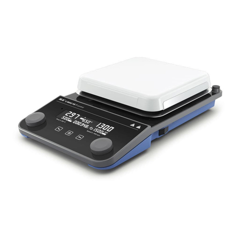
IKA Dry Block Heater 1 User manual

IKA DRY BLOCK HEATER 1
IKA DRY BLOCK HEATER 2
IKA DRY BLOCK HEATER 3
IKA DRY BLOCK HEATER 4
Betriebsanleitung DE 3
Ursprungssprache
Operating instructions EN 10
Mode d’emploi FR 17
Инструкция по эксплуатации
RU 24
使用说明 ZH 31
Indicationes de seguridad ES 38
Veiligheidsaanwijzingen NL 39
Norme di sicurezza IT 40
Säkerhetsanvisningar SV 41
Sikkerhedshenvisninger DA 42
Sikkerhetsveiledning NO 43
Turvallisuusohjeet FI 44
Indicações de segurança PT 45
Υποδείξείς ασφάλείας EL 46
Wskazówki bezpieczeństwa PL 47
Bezpečnostní pokyny CS 48
Biztonsági utasitások HU 49
Varnostna navodila SL 50
Bezpečnostné pokyny SK 51
Ohutusjuhised ET 52
Drošības norādījumi LV 53
Saugos nurodymai LT 54
Указания за безопасност BG 55
Instrucțiuni de siguranță RO 56

2
Pos. Bezeichnung Item Designation Pos. Désignation
A Netzbuchse A Power socket A Prise secteur
B KT-Buchse B KT socket B Prise KT
C Stativgewindebohrung C Threaded hole for stand C Alésage fileté du statif
D Kontaktstecker D Contact plug D Fiche de contact
E Geräteschalter E Main switch E Commutateur
F Taste "Start/Stop" F "Start/Stop" button F Touche "Start/Stop"
G Taste Timer "+" G Button timer "+" G Touche Timer "+"
H Taste Timer "-" H Button timer "-" H Touche Timer "-"
I Taste Timer/ Counter I Button Timer/ Counter I Touche Timer/ Counter
J Taste Heizung "+" J Button heating "+" J Touche chauffage "+"
K Taste Heizung "-" K Button heating "-" K Touche chauffage "-"
L LED Display Heizung L LED Display heating L Achage DEL chauffage
M LED (Set=Sollwert) M LED (set=set point value) M DEL (set=valeur théorique)
N LED externer Temperatursensor N LED external temperature sensor N DEL capteur de température externe
O LED Heizplatte O LED heating plate O DEL plaque chauffante
P LED Display Timer P LED display timer P Achage DEL minuteur
IKA DRY BLOCK HEATER 1
IKA DRY BLOCK HEATER 2
IKA DRY BLOCK HEATER 3
IKA DRY BLOCK HEATER 4
A C E
M
N
L
O
H
I G
J
KF
BD
P
序号 名称
A 电源插口
B 温度计插口
C 支杆螺孔
D 温度计短路接头
E 电源开关
F "开启/停止"按键
G 定时加时按键 "+"
H 定时减时按键 "-"
I 定时/计时按键
J 升温按键"+"
K 降温按键"-"
L 加热显示(LED)
M 设定温度显示(LED)
N 外置温度计显示(LED)
O 加热盘温度显示(LED)
p 定时显示(LED)
Поз. Наименование
A сетевую розетку
B
гнезду KT
C Резьбовое отверстие для штатива
D контактного разъема
E Главный выключатель
F Кнопка «Пуск/останов»
G Кнопка таймера "+"
H Кнопка таймера "-"
I Кнопка таймера/счетчик
J Кнопка нагревом "+"
K Кнопка нагревом "-"
L LED Индикация нагревом
M LED (Set = заданное значение)
N LED Внешний датчик температуры
O LED Установочная плита
p LED Индикация таймера

3
Ursprungssprache DE
Seite
EU-Konformitätserklärung 3
Zeichenerklärung 3
Sicherheitshinweise 4
Bestimmungsgemäße Verwendung 5
Auspacken 5
Montage von Stativstab 5
Bedienung 6
Betriebsmodi einstellen 6
Regelung der Mediumstemperatur mit Kontaktthermometer 7
Instandhaltung und Reinigung 7
Fehlercodes 8
Technische Daten 9
Gewährleistung 9
Inhaltsverzeichnis
Wir erklären in alleiniger Verantwortung, dass dieses Produkt den Bestimmungen der Richtlinien 2014/35/EU, 2014/30/EU und
2011/65/EU entspricht und mit den folgenden Normen und normative Dokumenten übereinstimmt: EN 61010-1, EN 61010-2-010,
EN 61326-1, EN 60529 und EN ISO 12100.
Eine Kopie der vollständigen EU-Konformitätserklärung kann bei [email protected] angefordert werden.
EU-Konformitätserklärung
Zeichenerklärung
VORSICHT
Gefährliche Situation, bei der die Nichtbeachtung des Sicherheitshinweises zu leichter Verletzung
führen kann.
WARNUNG
Gefährliche Situation, bei der die Nichtbeachtung des Sicherheitshinweises zu Tod oder schwerer
Verletzung führen kann.
GEFAHR (Extrem) gefährliche Situation, bei der die Nichtbeachtung des Sicherheitshinweises zu Tod oder
schwerer Verletzung führen kann.
Hinweis auf die Gefährdung durch eine heiße Oberfläche.
GEFAHR

4
Sicherheitshinweise
Zubehör
• Sicheres Arbeiten ist nur mit IKA Original Zubehör gewährleistet.
• Der externe Temperaturfühler muss beim Anschluss mindestens
20 mm tief in das Medium eingeführt werden.
• Montieren Sie Zubehör nur bei gezogenem Netzstecker.
• Zubehörteile müssen sicher mit dem Gerät verbunden sein und
dürfen sich nicht von alleine lösen. Der Schwerpunkt des Auf-
baus muss innerhalb der Aufstellfläche liegen.
• Beachten Sie die Betriebsanleitung des Zubehörs.
Zum Schutz des Gerätes
•
Das Gerät darf nur von einer Fachkraft geöffnet werden.
• Decken Sie das Gerät nicht ab, auch nicht teilweise, z. B. mit
metallischen Platten oder Folien. Die Folge ist Überhitzung.
• Vermeiden Sie Stöße und Schläge auf Gerät oder Zubehör.
• Achten Sie auf eine saubere Aufstellplatte.
• Bitte beachten Sie den Mindestabstand:
- zwischen Geräten: min. 100 mm.
- zwischen Gerät und Wand: min. 100 mm.
- über dem Gerät: min. 800 mm.
Spannungsversorgung / Abschalten des Gerätes
Nach einer Unterbrechung der Stromzu-
fuhr läuft das Gerät im Modus b von
selbst wieder an.
• Die Spannungsangabe des Typenschildes muss mit der
Netzspannung übereinstimmen.
• Die Steckdose für die Netzanschlussleitung muss leicht erreich-
bar und zugänglich sein.
• Die Trennung des Gerätes vom Stromversorgungsnetz erfolgt
nur durch Ziehen des Netz- bzw. Gerätesteckers.
Versuchsdurchführungen
Tragen Sie Ihre persönliche Schutzaus-
rüstung entsprechend der Gefahrenkla-
sse des zu bearbeitenden Mediums. An-
sonsten besteht eine Gefährdung durch:
- Spritzen und Verdampfen von Flüssigkeiten.
- Herausschleudern von Teilen.
- Freiwerden von toxischen oder brennbaren Gasen.
•Verwenden Sie flüssige Medien nur mit Block. Geben Sie flüssi-
ge Medien nie direkt auf die Heizplatte!
Allgemeine Hinweise
• Lesen Sie die Betriebsanleitung vor Inbetriebnahme vollständig
und beachten Sie die Sicherheitshinweise.
• Bewahren Sie die Betriebsanleitung für alle zugänglich auf.
•
Beachten Sie, dass nur geschultes Personal mit dem Gerät arbeitet.
• Beachten Sie die Sicherheitshinweise, Richtlinien, Arbeitss-
chutz-und Unfallverhütungsvorschriften.
• Steckdose muss geerdet sein (Schutzleiterkontakt).
Verbrennungsgefahr! Vorsicht beim
Berühren von Gehäuseteilen und Heiz-
platte.
Die Heizplatte kann gefährlich hohe Temperaturen erreichen.
Beachten Sie die Restwärme nach dem Ausschalten.
Das Gerät darf nur transportiert werden, wenn die Heizplatte
abgekühlt ist.
GEFAHR
Geräteaufbau
Verwenden Sie das Gerät nicht in explo-
sionsgefährdeten Bereichen, es ist nicht
EX-geschützt.
Bei Stoffen, die ein zündfähiges Gemisch bilden können, müs-
sen geeignete Schutzmaßnahmen, wie z.B. das Arbeiten unter
einem Abzug, ergriffen werden.
Zur Vermeidung von Personen- und Sachschäden beachten Sie
bei der Bearbeitung von gefährlichen Stoffen die einschlägigen
Schutz- und Unfallverhütungsmaßnahmen.
• Stellen Sie das Gerät frei auf einer ebenen, stabilen, sauberen,
rutschfesten, trockenen und feuerfesten Fläche auf.
• Die Gerätefüße müssen sauber und unbeschädigt sein.
• Stellen Sie sicher, dass das Netzkabel / Temperaturfühlerkabel
die Heizplatte nicht berührt.
• Prüfen Sie vor jeder Verwendung Gerät und Zubehör auf Bes-
chädigungen. Verwenden Sie keine beschädigten Teile.
GEFAHR
Zulässige Medien / Verunreinigung / Nebenreaktionen
Bearbeiten Sie nur Medien, bei denen der
Energieertrag durch das Bearbeiten unbe-
denklich ist. Dies gilt auch für andere En-
ergieeinträge, z. B. durch Lichteinstrahlung.
• Beachten Sie eine Gefährdung durch:
- entzündliche Materialien.
- brennbare Medien mit niedrigem Dampfdruck.
- Glasbruch.
- falsche Dimensionierung des Gefäßes.
- zu hohen Füllstand des Mediums.
- unsicheren Stand des Gefäßes.
• Verarbeiten Sie krankheitserregende Materialen nur in ges-
chlossenen Gefäßen unter einem geeigneten Abzug.
Mit diesem Gerät dürfen im unüber-
wachten und sicheren Betrieb nur Medi-
en bearbeitet bzw. erhitzt werden, deren
Flammpunkt über der eingestellten Sicherheitstemperaturbe-
grenzung liegt.
• Bedenken Sie eventuell auftretende Verunreinigungen und ge-
wollte chemische Reaktionen.
WARNUNG
VORSICHT
VORSICHT
WARNUNG

5
Auspacken
• Auspacken
- Packen Sie das Gerät vorsichtig aus.
- Nehmen Sie bei Beschädigungen sofort den Tatbestand auf
(Post, Bahn oder Spedition).
• Lieferumfang
- IKA DRY BLOCK HEATER,
je nach bestelltem Modell IKA DRY BLOCK HEATER 1, 2, 3, oder 4
- Netzkabel
- Temperaturfühler PT 1000.60
- Betriebsanleitung
Bestimmungsgemäße Verwendung
• Verwendung
- zum Erhitzen von Medien in Heizblöcken
• Verwendungsgebiet
Laborähnliche Umgebung im Innenbereich in Forschung,
Lehre, Gewerbe oder Industrie.
Der Schutz für den Benutzer ist nicht mehr gewährleistet:
- wenn das Gerät mit Zubehör betrieben wird, welches nicht
vom Hersteller geliefert oder empfohlen wird.
- wenn das Gerät in nicht bestimmungsgemäßem Gebrauch
entgegen der Herstellervorgabe betrieben wird.
- wenn Veränderungen an Gerät oder Leiterplatte durch
Dritte vorgenommen werden.
Montage von Stativstab
• Lesen Sie vor Verwendung die Montageanleitung und die Si-
cherheitshinweise der IKA Kreuzmuffe
• Das Gerät darf nicht am Stativstab aufgehängt werden!
WARNUNG
1. 2. 3.
17 mm
1.
2.3.
4.
1.
2.
3.
4.
Kippgefahr! Der Massenschwerpunkt des
angeschlossenen Geräts darf nicht über
den durch ein gestricheltes Rechteck ge-
kennzeichneten sicheren Bereich hinausragen.

6
Bedienung
IKA DRY BLOCK HEATER 1 IKA DRY BLOCK HEATER 2 IKA DRY BLOCK HEATER 3 IKA DRY BLOCK HEATER 4
InbetriebnahmeGeräteschalter (E) in OFF-Stellung bringen
Netzkabel in Netzbuchse (A) einstecken
Geräteschalter (E) in ON- Stellung bringen
Standard Modus A ist eingestellt (siehe “Betriebsmodi”)
HeizenSolltemperatur mit den Tasten Heizung +/- (J) und (K) einstellen
Der eingestellte Wert wird auf dem Display (L) angezeigt
Start der Heizfunktion durch Drücken der Taste "Start / Stop" (F)
Soll- und Ist- Temperatur wird im Wechsel auf dem Display ((L) blinkt) angezeigt:
iBei eingeschalteter Heizung leuchtet die LED (O).
iSolange die Temperatur der Aufstellfläche 50 °C überschreitet wird im
Standby-Betrieb auf dem Display (L) HOt angezeigt
AnschlussGeräteschalter (E) in OFF-Stellung bringen
externerKontaktstecker (D) abziehen
ThermometerSicherheitskontaktthermometer nach DIN 12878 Klasse 2 oder
Temperaturfühler PT 1000.60 mit Buchse (B) verbinden
(Regelung im Medium)Geräteschalter (E) in ON-Stellung bringen
iTemperaturfühler PT 1000
Die auf dem Display (L) angezeigte Ist-Temperatur des Temperaturfühlers
entspricht der Mediumstemperatur.
LED “externer Temperatursensor” PT 1000 (N) leuchtet.
Betriebsmodi einstellen
Gerätebetrieb mit Modus A oder b
Modus A
Alle eingestellten Werte bleiben nach dem Ausschalten oder dem
Trennen des Gerätes vom Netz erhalten. Nach dem Einschalten
des Gerätes ist der Status der Funktionen Heizen ausgeschaltet
(OFF).
Modus b
Alle eingestellten Werte bleiben nach dem Ausschalten oder
dem Trennen des Gerätes vom Netz erhalten. Nach dem Ein-
schalten des Gerätes wird der Status der Funktion Heizen vor
dem letzten Ausschalten übernommen (ON oder OFF).
Werkseinstellung: Modus A
Der eingestellte Modus wird beim Start des
Gerätes auf dem Display angezeigt.
Modus ändern
Geräteschalter (E) in OFF-Stellung bringen
Auswahltaste (F) gedrückt halten
Geräteschalter (E) in ON- Stellung bringen
Auswahltaste (F) loslassen
i Anzeige des eingestellten Modus auf dem
Display (P) b
A
Modus

7
Regelung der Mediumstemperatur mit Kontaktthermometer
Die Regelung der Mediumstemperatur mit Kontaktthermometer
ist zu bevorzugen. Man erhält damit nach Einstellung der Soll-
temperatur eine kurze Aufheizzeit, praktisch keine Temperatur-
drift und eine geringe Temperaturwelligkeit.
An der Rückseite des Gerätes befindet sich eine 6-polige Buch-
se zum Anschluss des Kontaktthermometers oder des Kontakt-
steckers. Die Elektronik des Gerätes liefert einen Prüfstrom der
über die Steckerstifte 3 und 5 der Buchse fließen muss, damit die
Heizplatte heizt.
Einstellungen
Die detaillierten Einstellanweisungen und Grenzwerte entneh-
men Sie der Betriebsanleitung des anzuschließenden Gerätes.
Am Kontaktthermometer wird die gewünschte Mediums-
temperatur eingestellt. Mit der Taste Heizung "+/-" (J) und
(K) des Gerätes wird die erforderliche Oberflächentempera-
tur der Heizplatte vorgewählt.
Sicherheitskontaktthermometer
nach DIN 12 878 Klasse 2 oder nach Gerstel werden mit einem
3-adrigen Kabel angeschlossen, der Prüfstrom fließt durch das
Kontaktthermometer.
Sicherheitsfunktion
Wird der Prüfstrom z.B. durch Bruch des Kontaktthermometers
oder Herausfallen des Kabelsteckers unterbrochen, schaltet die
Heizung ab. Über der Diodenbuchse ist auf einem Hinweis-
schild die erforderliche Steckerbelegung angegeben.
Kontaktthermometer ohne Sicherheitskreis
nach DIN 12 878 Klasse 0. Das Gerät heizt nur, wenn der Prüf-
stromkreis durch eine elektrische Verbindung der Steckerstifte
3 und 5 geschlossen ist.
Instandhaltung und Reinigung
Timer / Counter
Nach dem Einschalten des Gerätes kann über die Taste "Timer/
Counter" (I) zwischen den Funktionen Timer und Counter ge-
wechselt werden.
Timer
Durch Drücken der Tasten „+“ (G) und „-“ (H) kann eine Zeit-
spanne von bis zu 99 Stunden und 59 Min eingestellt werden.
Nach dem Aktivieren der Heizfunktion (F) läuft die voreingestell-
te Zeit ab. Nach dem Ablaufen der gesamten Zeit auf 00 Stunden
und 00 Minuten ertönt für 30 Sekunden ein Warnsignal, zusätz-
lich blinkt das Display. Die Heizfunktion wird deaktiviert.
Counter
Beim Start der Heizfunktion mit dem Taster (F) wird der Counter
aktiviert. Die Zeit im Countermodus wird von 00 Stunden 00 Mi-
nuten hochgezählt, bis die Heizfunktion unterbrochen wird. Der
Counter startet immer von 00:00 hh:mm.
Auswahl Timer / Counter
Durch Drücken des Tasters (I) kann zwischen dem Timer und
dem Counter gewechselt werden. Der Modus kann nur aktiviert
werden, wenn die Funktion Heizen eingeschaltet ist.
Das Gerät arbeitet wartungsfrei. Es unterliegt lediglich der natür-
lichen Alterung der Bauteile und deren statistischer Ausfallrate.
Reinigung
- Zum Reinigen den Netzstecker ziehen.
- Reinigen Sie IKA-Geräte nur mit von IKA freigegebenen
Reinigungsmittel.
Diese sind: (tensidhaltiges) Wasser und Isopropanol
- Tragen Sie zum Reinigen des Gerätes Schutzhandschuhe.
- Elektrische Geräte dürfen zu Reinigungszwecken nicht in das
Reinigungsmittel gelegt werden.
- Beim Reinigen darf keine Feuchtigkeit in das Gerät dringen.
- Falls andere als die empfohlenen Reinigungs- oder Dekontami-
nationsmethoden angewendet werden, fragen Sie bitte bei IKA
nach.
Ersatzteilbestellung
Bei Ersatzteilbestellungen geben Sie bitte Folgendes an:
- Gerätetyp,
- Seriennummer, siehe Typenschild des Produkts,
- Positionsnummer und Bezeichnung des Ersatzteils,
siehe www.ika.com.
- S
oftware-Version
Reparaturfall
Bitte senden Sie nur Geräte zur Reparatur ein, die gerei-
nigt und frei von gesundheitsgefährdenden Stoffen sind.
Fordern Sie hierzu das Formular „Unbedenklichkeitserklä-
rung“ bei IKA an oder verwenden Sie den download Ausdruck
des Formulares auf der IKA Website www.ika.com.
Senden Sie im Reparaturfall das Gerät in der Originalverpackung
zurück. Lagerverpackungen sind für den Rückversand nicht aus-
reichend. Verwenden Sie zusätzlich eine geeignete Transportver-
packung.

8
Fehlercodes
Eine Störung während des Betriebes wird durch eine Fehlermeldung im Display (LED (P)) angezeigt.
Gehen Sie dann wie folgt vor:
- Gerät am Geräteschalter (E) ausschalten
- Korrekturmaßnahmen treffen
- Gerät erneut starten
Fehlercode Ursache Folge Korrektur
E 3 Temperatur im Geräteinneren zu hoch Heizung aus Gerät ausschalten und abkühlen lassen
E 6 Unterbrechung im Sicherheitskreis Heizung aus - Kontaktstecker (D) stecken
- Kontaktthermometer PT 1000/ Temperatur-
fühler stecken
- Defekte Verbindungskabel, Stecker oder
Kontaktthermometer austauschen
E 25 Heizung- Schaltelementüberwachung Heizung aus - Gerät ausschalten
- Achtung! Nur für autorisiertes Serviceperso-
nal: Steckverbindungen des Heizelementes
im Geräteinneren überprüfen
E 26 Differenz Fühler Sicherheitstemperatur zu Heizung aus - Gerät ausschalten
Fühler Regeltemperatur - Achtung! Nur für autorisiertes Serviceperso-
Regeltemperatur > (Sicherheitstemperatur nal: Steckverbindungen der Temperatur-
+ 40 K) fühler im Geräteinneren überprüfen
Lässt sich der Fehler durch die beschriebenen Maßnahmen nicht beseitigen oder wird ein anderer Fehlercode angezeigt:
- wenden Sie sich bitte an die IKA Serviceabteilung,
- senden Sie das Gerät mit einer kurzen Fehlerbeschreibung ein.

9
Technische Daten
IKA IKA IKA IKA
DRY BLOCK DRY BLOCK DRY BLOCK DRY BLOCK
HEATER 1 HEATER 2 HEATER 3 HEATER 4
Betriebsspannungsbereich Vac (220 ... 230) ± 10%
Vac 115 ± 10%
Vac 100 ± 10%
Nennspannung Vac 230 / 50 Hz
Vac 115 / 60 Hz
Vac 100 / 60 Hz
Frequenz Hz 50 / 60
Anzeige digital
Temperaturbereich °C Raumtemperatur + 5 ... 120
Timer min/h 1 min ... 99 h 59 min
Zul. Einschaltdauer % 100
Zul. Umgebungstemperatur °C +5 ... +40
Zul. relative Feuchte % 80
Schutzart nach DIN EN 60529 IP 21
Schutzklasse I
Überspannungskategorie II
Verschmutzungsgrad 2
Geräteeinsatz über NN m max. 2000
Abmessung (B x T x H) mm 151 x 228 x 73 151 x 304 x 73 151 x 380 x 73
151 x 456 x 73
Gewicht kg 1,3 1,7 2,0 2,0
Heizen
Leistungsaufnahme (+10%) max. bei 230 Vac W 165 250 330 412
115 Vac 165 250 330 412
100 Vac 165 250 330 412
Abweichung Temperaturmessfühler PT 1000 K < + 0,1*
DIN EN 60751 Kl. A
Temperaturkonstanz innerhalb der Blöcke bei 37°C
°C +0,2 +0,2 +0,2 +0,2
Temperaturkonstanz innerhalb der Blöcke bei 60 ºC
°C +0,4 +0,4 +0,4 + 0,4
Temperaturhomogenität bei 37°C
K +0,2 +0,2 +0,3 +0,3
Temperaturhomogenität bei
60 ºC
K +0,4 +0,4
+0,6 +0,6
Heizrate / Aufheizzeit mit PT 1000
K/min 5,0
4,5 4,0 4,0
Fest eingestellter Sicherheitskreis
Sicherheitstemperaturgrenze °C 150
* Testbedingungen: mit Testblock und Glasgefäß gefüllt mit M 50 Öl
Technische Änderungen vorbehalten!
Gewährleistung
Die Gewährleistung erstreckt sich nicht auf Verschleißteile und
gilt nicht für Fehler, die auf unsachgemäße Handhabung und un-
zureichende Pflege und Wartung, entgegen den Anweisungen in
dieser Betriebsanleitung, zurückzuführen sind.
Entsprechend den
IKA
-Verkaufs-und Lieferbedingungen beträgt
die Gewährleistungszeit 24 Monate. Im Gewährleistungsfall
wenden Sie sich bitte an Ihren Fachhändler, oder senden Sie das
Gerät unter Beifügung der Lieferrechnung und Nennung der
Reklamationsgründe direkt an unser Werk. Frachtkosten gehen
zu Ihren Lasten.

10
Source language: German EN
Page
EU Declaration of conformity 10
Explication of warning symbols 10
Safety instructions 11
Intended use 12
Unpacking 12
Assembling the support rod 12
Operation 13
Setting the operating mode 13
Controlling the temperature via contact thermometer 14
Maintenance and cleaning 14
Error codes 15
Technical data 16
Warranty 16
Contents
We declare under our sole responsibility that this product corresponds to the directives 2014/35/EU, 2014/30/EU and 2011/65/EU
and conforms with the following standards or normative documents: EN 61010-1, EN 61010-2-010, EN 61326-1, EN 60529 and EN
ISO 12100.
EU Declaration of conformity
Explication of warning symbols
CAUTION
Indicates a potentially hazardous situation, which, if not avoided, can result in injury.
WARNING
Indicates a hazardous situation, which, if not avoided, can result in death, serious injury.
DANGER
Indicates an (extremely) hazardous situation, which, if not avoided, will result in death, serious injury.
Indicates the exposure to a hot surface.
DANGER

11
Safety instructions
Accessories
• Safe operation is guaranteed only with the use of original IKA
accessories.
• Ensure that the external temperature sensor is inserted into the
medium to a depth of at least 20 mm when connected.
• Always disconnect the plug before attaching accessories.
• Accessories must be securely attached to the device and can-
not come off by themselves. The centre of gravity of the assem-
bly must lie within the surface on which it is set up.
• Observe the operating instructions of the accessories.
For protection of the equipment
•
The device may only be opened by qualified and IKA approved ex-
perts.
• Do not cover the device, even partially e.g. with metallic plates
or film. This may result in overheating.
• Protect the device and accessories from bumps and impacts.
• Keep the base plate clean.
• Observe the minimum distances:
- between devices min. 100 mm,
- between device and wall min. 100 mm,
- above the device min. 800 mm.
Power supply / Switching off the device
The device will automatically restart in
mode b following any interruption to the
power supply.
• The voltage stated on the type plate must correspond to the
mains voltage.
• The outlet for the mains plug must be easily accessible.
• The device can only be disconnected from the mains outlet by
pulling out the power cord set or the connector plug.
Procedures during sample runs
Wear your personal protective equipment
in accordance with the hazard category
of the media to be processed. There may
be a risk from:
- splashing and evaporation of liquids,
- ejection of parts,
- release of toxic or combustible gases.
• Do not heat liquid media except with the block. Never pour
liquid media directly on to the heating plate!
General information
• Read the operating instructions in its entirety before using the
device and follow the safety instructions.
• Keep the operating instructions in a place where it can be ac-
cessed by everyone.
• Ensure that only trained staff work with the device.
• Follow the safety instructions, guidelines, occupational health
and safety and accident prevention regulations.
• Electrical outlet must be grounded (protective ground contact).
Risk of burns! Exercise caution when
touching parts of the housing and the
heating plate.
The heating plate can reach dangerous temperatures. Pay at-
tention to the residual heat on the heating plate after switching
off the stirrer.
The device may only be transported when the heating plate has
cooled down.
DANGER
Device design
Do not use the device in explosive atmo-
spheres, it is not EX-protected.
With substances capable of forming an
explosive mixture, appropriate safety measures must be ap-
plied, e.g. working under a fume hood.
To avoid body injury and property damage, observe the rele-
vant safety and accident prevention measures when processing
hazardous materials.
• Set up the device in a spacious area on an even, stable, clean,
non-slip, dry and fireproof surface.
• The feet of the device must be clean and undamaged.
• Ensure that the power cord set / temperature sensor cable does
not touch the heating plate.
• Check the device and accessories for damage before each use.
Do not use damaged components.
DANGER
Permissible medium / contaminants / side reactions
Only process media that will not react
dangerously to the extra energy pro-
duced through processing. This also ap-
plies to any extra energy produced in other ways, e.g. through
light irradiation.
• Beware of hazards due to:
- flammable materials,
- combustible media with a low boiling temperature,
- glass breakage,
- incorrect container size,
- overfilling of media,
- unsafe condition of container.
• Process pathogenic materials only in closed vessels under a
suitable fume hood.
In unsupervised and safe operation, this
device may only handle or heat media
whose flash point is above the set safety
temperature limit. (acc. to EN 61010-2-010)
• Please consider any possible contaminations and unwanted
chemical reactions.
WARNING
CAUTION
CAUTION
WARNING

12
Intended use
• Use
- For heating media in block heaters
• Area of use
Indoor environments similar to that a laboratory of research,
teaching, trade or industry area.
The safety of the user cannot be guaranteed:
- if the device is operated with accessories that are not sup-
plied or recommended by the manufacturer,
- if the device is operated improperly or contrary to the
manufacture’s specifications,
- if the device or the printed circuit board are modified by
third parties.
Assembling the support rod
• Review the mounting and safety instructions of the IKA boss
head clamp prior to using it.
• The device must not be suspended from the support rod!
WARNING
1. 2. 3.
17 mm
1.
2.3.
4.
1.
2.
3.
4.
Risk of tipping! Make sure that the cen-
ter of mass of the attached device does
not protrude over the safe area indicated
below with a dotted rectangle.
Unpacking
• Unpacking
- Please unpack the device carefully
- In the case of any damage a fact report must be sent imme-
diately (post, rail or forwarder)
• Scope of delivery
- IKA DRY BLOCK HEATER
Depending on the IKA DRY BLOCK HEATER model 1, 2, 3, or
4
- Mains cable
- Temperature sensor PT 1000.60
- Operating instructions

13
Operation
Setting operating mode
Operating the device in mode A or b
Mode A
All settings will be stored if the device is switched off or discon-
nected from the power supply. The heating functions will be set
to OFF when the device is powered on.
Mode b
All settings will be stored if the device is switched off or discon-
nected from the power supply. The heating function will be set
to ON or OFF when the device is powered on, depending on the
previous status of the device.
Factory setting: mode A
The mode selected will be shown on the display when the
device is started up.
Change the mode
Move device switch (E) to the OFF position
Keep the selection button (F) depressed
Move device switch (E) to the ON position
Release the selection button (F)
i The set mode is indicated on the
Display (P) b
IKA DRY BLOCK HEATER 1 IKA DRY BLOCK HEATER 2 IKA DRY BLOCK HEATER 3 IKA DRY BLOCK HEATER 4
CommissioningMove device switch (E) to the OFF position
Insert the mains power cable into the power socket (A)
Move device switch (E) to the ON position
The unit will be set to factory setting mode A (see “Setting operating mode”)
HeatingSet the target temperature using the heater buttons +/- (J) and (K)
The value selected will be shown on the display (L)
Start the heating function by pressing the "Start / Stop" button (F)
The set-point and actual temperatures will be shown alternately on the display ((L) is blinking):
iWhen the heating is on, the LED (O) lights up.
iDuring standby operation, the display (L) will show HOt if the base plate tempe-
ature is above 50 °C
ConnectingMove device switch (E) to the OFF position
externalDetach contact plug (D)
thermometersAttach a DIN 12878 (Class 2) compliant safety contact thermometer or a
(direct temperature PT 1000.60 temperature sensor to the socket (B)
control in the media)Move device switch (E) to the ON position
iTemperature sensor PT 1000
The actual temperature for the temperature sensor shown on
display (L) will correspond to the temperature of the media.
The LED "external temperature sensor"” PT 1000 (N) will be lit.
A
Mode

14
Controlling the temperature via contact thermometer
The preferable method for controlling the average temperature
is with the contact thermometer. After the set point temperature
has been adjusted, this results in a short heating-up time, practi-
cally no temperature drift and only minor fluctuation in tempe-
rature.
A 6-pin jack is located on the rear side of the instrument for
connecting the contact thermometer or the contact plug. The
electronics of the instruments returns a test current that must
flow via connector pins 3 and 5 for the heating plate to heat up.
Settings
For the detailed instructions for settings and limit values, refer to
the operating instructions for the instrument you are connecting.
The target temperature of the medium is set at the contact
thermometer. The heater buttons +/- (J) and (K) on the de-
vice can be used to preselect the required surface tempera-
ture of the heating plate.
Safety contact thermometers
acc. to DIN 12 878 class 2 or acc. Gerstel are connected with
a three-wire cable, the test current flows through the contact
thermometer.
Safety function
If the test current is interrupted because of e.g. breakage of
contact thermometer or falling out of the cable plug, the hea-
ting cuts off. The required plug allocation is indicated on a refe-
rence plate above the diode bushing.
Contact thermometer without safety circuit
acc. to DIN 12 878 class 0. The instrument only heats if the test
current circuit is closed by an electrical connection of the plug
pins 3 and 5.
Maintenance and cleaning
The device is maintenance-free. It is only subject to the natural
wear and tear of components and their statistical failure rate.
Cleaning
- For cleaning disconnect the mains plug!
- Use only cleaning agents which have been approved by IKA to
clean IKA devices.
These are water (with tenside) and isopropanol.
- Wear protective gloves during cleaning the devices.
- Electrical devices may not be placed in the cleansing agent for
the purpose of cleaning.
- Do not allow moisture to get into the device when cleaning.
- Before using another than the recommended method for
cleaning or decontamination, the user must ascertain with IKA
that this method does not destroy the device.
Timer / Counter
After the device has been switched on, the "Timer/ Counter" but-
ton (I) can be used to toggle between timer mode and counter
mode.
Timer
Pressing the buttons "+" (G) and "-" (H) allows selection of a
time period of up to 99 hours and 59 minutes. Once the heating
function (F) is activated, the preset time starts to run. When the
total time has run down to 00 hours and 00 minutes, a warning
buzzer sounds for 30 seconds and in addition the display flashes.
The heating function is then deactivated.
Counter
When the heating function is stated by pressing the button (F)
the counter is activated. In counter mode the time is counted
upwards from 00 hours 00 minutes until the heating function is
stopped. The counter always starts from 00:00 hh:mm.
Selection of Timer / Counter
Pressing the button (I) toggles between timer mode and counter
mode. The mode can be activated only when the heating func-
tion is off.
Spare parts order
When ordering spare parts, please give:
- device type.
- serial number, see type plate.
- position number and description of spare part,
see www.ika.com.
- software version
Repair
Please only send devices in for repair that have been clea-
ned and are free of materials which might present health
hazards.
For repair, please request the “Safety Declaration (Deconta-
mination Certificate)” from IKA or use the download printout
of it from IKA website at www.ika.com.
If your appliance requires repair, return it in its original packaging.
Storage packaging is not sucient when sending the device -
also use appropriate transport packaging.

15
Error codes
Any malfunctions during operation will be identified by an error message on the display (LED (P)).
Proceed as follows in such cases:
- Switch off device using the main switch (E)
- Carry out corrective measures
- Restart device
Error code Cause Effect Solution
E 3 Temperature inside device too high Heating off Switch off device and allow to cool down
E 6 Break in safety circuit Heating off - Plug in contact plug (D)
- Plug in PT 1000 contact thermometer /
temperature sensor
- Replace faulty connecting cable, plug, or
contact thermometer
E 25 Heating and switching element monitoring Heating off - Switch off device
- Warning! Only to be carried out by autho-
rised service personnel: Carry out an internal
test on the device to check the plug-in
connector for the heating element
E 26 Difference between temperature of safety Heating off - Switch off device
sensor and temperature of control sensor - Warning! Only to be carried out by autho-
control temperature > (safety temperature rised service personnel: Carry out an internal
+ 40 K)) test on the device to check the temperature
sensor
If the actions described fail to resolve the fault or another error code is displayed then take one of the following steps:
- contact the IKA service department,
- send the device for repair, including a short description of the fault.

16
Technical Data
IKA IKA IKA IKA
DRY BLOCK DRY BLOCK DRY BLOCK DRY BLOCK
HEATER 1 HEATER 2 HEATER 3 HEATER 4
Operating voltage range Vac (220 ... 230) ± 10%
Vac 115 ± 10%
Vac 100 ± 10%
Rated voltage Vac 230 / 50 Hz
Vac 115 / 60 Hz
Vac 100 / 60 Hz
Frequence Hz 50 / 60
Display digital
Temperature range °C ambient temperature +5 ... 120
Timer min/h 1 min ... 99 h 59 min
Perm. duration of operation % 100
Perm. ambient temperature °C +5 ... +40
Perm. humidity % 80
Protection acc. to DIN EN 60529 IP 21
Protection class I
Overvoltage category II
Contamination level 2
Operation at a terrestrial altitude m max. 2000
Dimension (W x D x H) mm 151 x 228 x 73 151 x 304 x 73 151 x 380 x 73 151 x 456 x 73
Weight kg 1.3 1.7 2.0 2.0
Heating
Power consumption (+10%) max. at 230 Vac W 165 250 330 412
115 Vac 165 250 330 412
100 Vac 165 250 330 412
Temperature sensor PT 1000 variation K < + 0.1*
DIN EN 60751 Kl. A
Temperature stability within the blocks at 37 ºC
°C +0.2 +0.2 +0.2 +0.2
Temperature stability within the blocks at 60 ºC
°C
+0.4 + 0.4 +0.4 +0.4
Temperature homogenity within the the blocks at 37 ºC
K +0.2 +0.2 +0.3 +0.3
Temperature homogenity within the the blocks at 60 ºC
K +0.4 +0.4 + 0.6 +0.6
Heating rate (PT 1000 in solid block)
K/min 5.0 4.5 4.0 4.0
Fixed safety circuit
Safety temperature limit °C 150
* Test parameter: with test block and glass vessel filled with M50 oil
Subject to technical changes!
Warranty
The warranty does not cover worn out parts, nor does it apply
to faults resulting from improper use, insucient care or mainte-
nance not carried out in accordance with the instructions in this
operating manual.
In accordance with IKA warranty conditions, the warranty period
is 24 months. For claims under the warranty please contact your
local dealer. You may also send the machine direct to our factory,
enclosing the delivery invoice and giving reasons for the claim.
You will be liable for freight costs.

17
Langue d'origine: allemand FR
Page
Déclaration UE de conformité 17
Explication des symboles 17
Consignes de sécurité 18
Utilisation conforme 19
Déballage 19
Assemblage de la tige statif 19
Fonctionnement 20
Régler les modes d‘utilisation 20
Réglage de la température du milieu avec thermocontact 21
Entretien et nettoyage 21
Codes d’erreur 22
Caractéristiques techniques 23
Garantie 23
Sommaire
Nous déclarons sous notre seule responsabilité que le présent produit est conforme aux prescriptions des directives 2014/35/UE,
2014/30/UE et 2011/65/UE, ainsi qu‘aux normes et documents normatifs suivants: EN 61010-1, EN 61010-2-010, EN 61326-1, EN
60529 et EN ISO 12100.
Une copie de la déclaration de conformité UE complète peut être demandée en adressant un courriel à l’adresse [email protected].
Déclaration UE de conformité
Explication des symboles
PRUDENCE
Situation dangereuse dans laquelle le non respect des prescriptions de sécurité peut causer des bles-
sures graves.
AVERTISSEMENT
Situation dangereuse dans laquelle le non respect des prescriptions de sécurité peut causer la mort
ou des blessures graves.
DANGER
Situation (extrêmement) dangereuse dans laquelle le non respect des prescriptions de sécurité peut
causer la mort ou des blessures graves.
Avertit d‘un risque dû à une surface chaude.
DANGER

18
Consignes de sécurité
Accessoires
• La sécurité du travail n‘est garantie qu‘en utilisant les acces-
soires d‘origine IKA.
• Avant de brancher la sonde de température externe, l’immerg-
er dans le milieu à une profondeur d’au moins 20 mm.
• Ne monter les accessoires que lorsque la fiche secteur est
débranchée.
• Les accessoires doivent être raccordés solidement à l‘appareil
pour empêcher tout risque de desserrage accidentel. Le centre
de gravité de la structure doit se trouver dans la surface d‘ap-
pui.
• Respecter le mode d‘emploi des accessoires.
Pour protéger l‘appareil
• L‘appareil ne doit être ouvert que par un personnel qualifié.
• Ne pas couvrir l‘appareil, entièrement ou partiellement, de
plaques ou films métalliques ou autres. L‘appareil risquerait de
surchauffer.
• Éviter les chocs et les coups sur l‘appareil ou sur les accessoires.
• Veiller à ce que la plaque chauffante soit propre.
• Respecter les distances minimales suivantes :
- entre les appareils : au moins 100 mm,
- entre l‘appareil et le mur : au moins 100 mm,
- au dessus de l‘appareil : au moins 800 mm.
Alimentation / arrêt de l‘appareil
Après interruption de l‘alimentation élec-
trique, l‘appareil redémarre automatique-
ment en mode b.
• La tension nominale de la plaque signalétique doit correspon-
dre à la tension du secteur.
• La prise de courant utilisée pour le branchement au secteur
doit être facile d’accès.
• L‘appareil est séparé du réseau électrique uniquement en
débranchant la fiche secteur ou la fiche de l‘appareil.
Réalisation des essais
Porter l‘équipement de protection indivi-
duelle correspondant à la classe de dan-
ger du milieu à traiter. Faute de quoi, il
existe un danger par :
- projection et évaporation de liquides,
- éjection de pièces,
- libération de gaz toxiques ou inflammables.
• Utilisez des milieux liquides uniquement avec le bloc.Ne versez
jamais les milieux liquides directement sur la plaque chauffante
Consignes générales
• Lire le mode d’emploi dans son intégralité avant la mise en
service et respecter les consignes de sécurité.
• Conserver le mode d’emploi de manière à ce qu’il soit accessi-
ble à tous.
• Veiller à ce que seul un personnel formé travaille avec l‘appareil.
• Respecter les consignes de sécurité, les directives la réglemen-
tation de sécurité au travail et de prévention des accidents.
• La prise doit être mise à la terre (contact à conducteur de pro-
tection).
Risque de brûlure ! Toucher prudem-
ment les pièces du logement et la plaque
chauffante.
La plaque chauffante peut atteindre des températures élevées
et dangereuses. Attention à la chaleur résiduelle après l‘arrêt !
Ne transporter l’unité que lorsque la plaque chauffante a refroi-
di.
DANGER
Structure de l‘appareil
N’utilisez pas l’appareil dans des atmo-
sphères explosives, comme il n’est pas
doté de protection EX.
En cas de substances pouvant former un mélange inflammable,
il faut prendre des mesures de protection adéquate, comme,
par ex., travailler sous une hotte d’aspiration.
Pour éviter les blessures et les dommages matériels, veuillez re-
specter, lors de la transformation de substances dangereuses,
les mesures de protection et de prévention des accidents appli-
cables.
• Placer l‘appareil à un endroit dégagé sur une surface plane,
stable, propre, non glissante, sèche et non inflammable.
• Les pieds de l‘appareil doivent être propres et en bon état.
• Vérifier que le câble d’alimentation / le câble de la sonde de
température ne touchent pas la plaque chauffante.
• Avant chaque utilisation, contrôler l‘état de l‘appareil et des
accessoires. Ne pas utiliser de pièces endommagées.
DANGER
Milieux autorisés / Impuretés / Réactions secondaires
Ne traiter que des substances pour
lesquelles l‘énergie dégagée pendant le
traitement ne pose pas problème. Ceci
s‘applique également aux autres apports d‘énergie, par ex. le
rayonnement lumineux.
• Attention aux risques suivants :
- matériaux inflammables,
- milieux combustibles à faible pression de vapeur,
- bris de verre,
- mauvais dimensionnement du récipient,
- remplissage excessif du milieu,
- état non stable du récipient.
• Ne traiter les substances pathogènes que dans des récipients
fermés et sous une hotte d‘aspiration adaptée.
En fonctionnement non surveillé et sûr,
cet appareil ne doit traiter ou chauffer
que des fluides dont le point d’éclair se
situe au-dessus de la limite de température de sécurité définie.
(selon EN 61010-2-010)
• Attention aux impuretés et réactions chimiques non souhaitées.
AVERTISSEMENT
PRUDENCE
PRUDENCE
AVERTISSEMENT

19
Déballage
• Déballage
- Déballer l’appareil avec précaution.
- En cas de dommages, établir immédiatement un constat
correspondant (poste, chemin de fer ou transporteur).
• Contenu de la livraison
- IKA DRY BLOCK HEATER,
en fonction du modèle IKA DRY BLOCK HEATER 1,2, 3, ou
4
- Câble connecteur
- Sonde de mesure de température PT 1000.60
- Mode d‘emploi
Utilisation conforme
• Utilisation
- Sur le chauffage des liquides dans les blocs chauffants
• Domaine d’application
Environnements intérieurs similaires à des laboratoires de
recherche, d‘enseignement, commerciaux ou industriels.
La protection de l‘utilisateur n‘est plus assurée :
- si l‘appareil est utilisé avec des accessoires non fournis ou
non recommandés par le fabricant,
- si l‘appareil est utilisé de manière non conforme, sans res-
pecter les indications du fabricant,
- si des modifications ont été apportées à l‘appareil ou au
circuit imprimé par des tiers.
Assemblage de la tige statif
• Avant l‘utilisation, lire les instructions de montage et les consi-
gnes de sécurité des noix de serrage IKA.
• L‘appareil ne doit pas être suspendu par la tige statif !
AVERTISSEMENT
1. 2. 3.
17 mm
1.
2.3.
4.
1.
2.
3.
4.
Risque de basculement ! Le centre de
gravité de l‘appareil raccordé ne doit pas
saillir de la zone de sécurité signalée par
un rectangle rayé.

20
Fonctionnement
Régler les modes d’utilisation
Fonctionnement de l'appareil en mode A ou b
Mode A
Toutes les valeurs réglées sont conservées après l'arrêt ou le dé-
branchement de l'appareil du secteur. Après la mise en marche
de l'appareil, le statut des fonctions mélanger et chauffer est
désactivé (OFF).
Mode b
Toutes les valeurs réglées sont conservées après l'arrêt ou le dé-
branchement de l'appareil du secteur. Après la mise en marche
de l'appareil, le statut des fonctions chauffer avant la désactiva-
tion est repris (ON ou OFF).
Réglage d’usine: Mode A
Le mode réglé s'affiche au démarrage de l'appareil.
Modifier le mode
Placez l'interrupteur de l'appareil (E) sur OFF
Maintenir enfoncée la touche de sélection (F)
Placez l'interrupteur de l'appareil (E) sur ON
Relâcher la touche de sélection (F)
i La mode réglée i s'ache à l'écran (P)
b
A
Mode
IKA DRY BLOCK HEATER 1 IKA DRY BLOCK HEATER 2 IKA DRY BLOCK HEATER 3 IKA DRY BLOCK HEATER 4
Mise en servicePlacez l‘interrupteur de l‘appareil (E) sur OFF
Insérez le câble secteur dans la prise secteur (A)
Placez l‘interrupteur de l‘appareil (E) sur ON
Le mode A (réglage d‘usine) est réglé par défaut (voir “Modes de fonctionnement”)
ChaufferRéglez la température de consigne avec les touches de chauffage +/- (J) et (K)
La valeur réglée s‘ache à l‘écran (L)
Démarrage de la fonction de chauffage en appuyant sur la touche "Start / Stop" (F)
Les températures théorique et réelle s‘achent en alternance sur l‘achage ((L) clignote):
iQuand le chauffage est allumé, la LED (O) s'allume,
iTant que la température de la surface d‘appui dépasse 50 °C, l‘achage a lieu en
mode stand-by sur l‘achage (L) HOt
BranchementPlacez l'interrupteur de l'appareil (E) sur OFF
d'un thermo-Débranchez la fiche à contact (D)
mètre externeReliez le thermocontact selon DIN 12878 classe 2 ou
(régulation de tempéra- la sonde de température PT 1000.60 avec la prise (B)
ture directe dans le milieu)Placez l'interrupteur de l'appareil (E) sur ON
iCapteur température PT 1000
A l'achage (L), la température réelle indiquée de la sonde de température
correspond à la température du milieu.
La DEL ”Sonde de température externe” PT 1000 (N) s'allume
Other manuals for Dry Block Heater 1
1
This manual suits for next models
3
Table of contents
Other IKA Laboratory Equipment manuals
Popular Laboratory Equipment manuals by other brands

REITEL
REITEL SUPERSTEAM operating instructions

Droplet
Droplet UHSAS Operator's manual

Helmer Scientific
Helmer Scientific i.C3 iLR105-GX user guide

W&H Med
W&H Med Lisa VA131-17 Instructions for use

Dionex
Dionex ICS-90 Operator's manual

Philadelphia Scientific
Philadelphia Scientific iBos Charger-Splitter Operation manual