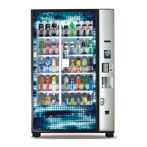
GPL 6500 Manual

DO NOT REMOVE
MANUAL FROM
MACHINE
GPL ♦165 Bridgepoint Drive ♦South St. Paul MN 55075
Part # 80390445041
GPL 6500 V2.41108
Refrigerated Glassfront
Model 6500
Set-Up / Programming / Parts Guide

i

ii
Warranty.............................................................................................................................................................iii
Introduction.........................................................................................................................................................iv
Features ............................................................................................................................................................. v
Specifications ..................................................................................................................................................... v
Installation ..................................................................................................................................................... 1.01
Cautions ........................................................................................................................................... 1.01
Unpacking ........................................................................................................................................ 1.02
Leveling the Machine ...................................................................................................................... 1.02
Door Hinge ....................................................................................................................................... 1.03
Set Up Steps .................................................................................................................................... 1.04
Optional Equipment....................................................................................................................................... 2.01
Refrigeration.................................................................................................................................................. 2.02
Components.................................................................................................................................................. 3.01
Power Supply ................................................................................................................................... 3.01
Lighting System................................................................................................................................ 3.01
Main Product Shelves ...................................................................................................................... 3.01
Delivery Bin ...................................................................................................................................... 3.01
Vend Motors..................................................................................................................................... 3.02
Logic Board & Display...................................................................................................................... 3.03
Keypad ............................................................................................................................................. 3.03
Coin Mechs, Validators and Card Readers...................................................................................... 3.03
PosiVend™ ................................................................................................................................................... 3.04
Operating System.......................................................................................................................................... 4.01
Power Up State ................................................................................................................................ 4.01
Motor Scan....................................................................................................................................... 4.01
Standby ............................................................................................................................................ 4.01
Keypad ............................................................................................................................................. 4.01
Credit Accumulation ......................................................................................................................... 4.01
Vend Process................................................................................................................................... 4.02
Change Payback .............................................................................................................................. 4.02
Use Correct Change......................................................................................................................... 4.02
Token Vends .................................................................................................................................... 4.02
Accountability Information ................................................................................................................ 4.02
Shutdowns........................................................................................................................................ 4.02
DEX/UCS ......................................................................................................................................... 4.02
Programming................................................................................................................................................. 5.01
Service Modes.................................................................................................................................. 5.03
Parts.............................................................................................................................................................. 6.01
Service/Trouble Shooting.............................................................................................................................. 7.01
To achieve the most trouble-free operation from your Fusion Merchandiser, it is highly recommended that this
service manual be thoroughly read and the instructions followed pertaining to installation, servicing and
maintaining of the unit.
Should you have questions pertaining to this manual or the vendor, please contact your GPL distributor or
write directly to: Product Support Group
GPL
165 Bridgepoint Drive
St. Paul, MN 55107 USA
651-288-2975 or 800-523-5932
651-288-2971 (fax)
www.cranems.com
©2007 GPL
TABLE OF CONTENTS
GPL 6500 1008
Rev 2.4

iii
LIM IT ED EXPRESS WARRANTY
GPL warrants these automatic merchandisers (the "Unit"), manufactured by it, to be free under normal use and service from defects in
material or workmanship for a period of two (2) years from the date of delivery of this Unit to the ori inal purchaser who purchased the
Unit either directly from GPL or from an authorized GPL dealer or distributor (“GPL Dealer/Distributor”). This warranty extends only to
the ori inal purchaser of the Unit, but only if purchased either directly from GPL or from an authorized GPL Dealer/Distributor (“Ori inal
Purchaser”), and is limited to the repair or replacement, at GPL's sole option, of any part or parts of the Unit that are returned to GPL or
to the authorized GPL Dealer/Distributor from whom the Unit was ori inally purchased, with all transportation char es prepaid by
Ori inal Purchaser, and which, on GPL's examination, such returned part or parts shall conclusively appear to have been defective.
This warranty does not extend to:
1. Any Unit, or part thereof, that was subjected to misuse, ne lect, or accident by anyone other than GPL after its delivery to the
Ori inal Purchaser;
2. Any Unit, or part thereof, that was modified, altered, incorrectly wired or improperly installed by anyone other than GPL or used in
violation of the instructions provided by GPL;
3. A Unit, or part thereof, which has been repaired or altered by anyone other than GPL or an authorized GPL Dealer/Distributor;
4. A Unit, or part thereof, which has had the serial number removed, defaced, or otherwise altered;
5. Any plastic or lass windows, lamps, fluorescent tubes, and water contact parts;
6. Any Unit used outdoors;
7. Any accessories used with the Unit that were manufactured by some person or entity other than GPL; or
8. Any Unit repaired within the warranty period with parts other than enuine GPL built or endorsed parts.
GPL DISCLAIMS ALL OTHER WARRANTIES OF ANY KIND AS TO THE UNIT AND ALL
WARRANTIES OF ANY KIND AS TO ANY ACCESSORIES. THIS DISCLAIMER OF
WARRANTIES INCLUDES (1) ANY EXPRESS WARRANTIES OTHER THAN THE
LIMITED WARRANTY PROVIDED ABOVE AS TO THE UNIT AND (2) ALL IMPLIED
WARRANTIES OF MERCHANTABILITY AND FITNESS FOR A PARTICULAR PURPOSE
AS TO THE UNIT AND ANY ACCESSORIES. UNDER NO CIRCUMSTANCES SHALL
GPL BE RESPONSIBLE FOR ANY INCIDENTAL, CONSEQUENTIAL OR SPECIAL
DAMAGES, LOSSES OR EXPENSES (INCLUDING BUT NOT LIMITED TO LOST
PROFITS, LOST SALES, INJURY TO PERSON OR PROPERTY) ARISING FROM OR IN
CONNECTION WITH THE USE OF, OR THE INABILITY TO USE, THE UNIT FOR ANY
PURPOSE WHATSOEVER REGARDLESS OF THE LEGAL THEORY (CONTRACT,
TORT OR OTHER). IN NO EVENT WILL GPL BE OBLIGATED TO PAY DAMAGES FOR
ANY AMOUNT EXCEEDING THE PRICE PAID FOR THE UNIT. No representative of GPL or any other
person is authorized to assume for GPL, or a ree to on the behalf of GPL, any other liability or warranty in connection with the sale of
this Unit.
GPL reserves the ri ht to make any chan es or improvements in its products without notice and without obli ation, and without bein
required to make correspondin chan es or improvements in Units theretofore manufactured or sold.
165 Bridgepoint Drive
South St. Paul, MN 55075 USA
651-288-2975
651-288-2971 (fax)
Rev 2.4

iv
INTRODUCTION
The Fusion features simple operation and built in flexibility, as well as extensive diagnostics and error
reporting facilities to provide ease of maintenance.
HOW TO USE THIS MANUAL
This manual is divided into seven basic parts:
1. Unpacking and Installation.
2. Optional Equipment & Refrigeration
3. Components and Refrigeration.
4. Operating System.
5. Programming
6. Parts
7. Troubleshooting.
CAUTION: Certain procedures in both the operating section and the service
section require that voltage be on in the machine. Only, trained personnel
should perform this function. Exercise extreme caution while performing these
procedures. These procedures will be marked with the lightening bolt symbol
as it appears at left.
CAUTION: Certain procedures in both the operating section and the service
section require a qualified trained technician to perform the particular task at
hand. These procedures will be marked with the exclamation symbol as it
appears at left.
GPL 6500 V2.31008
ADDENDUM – EXTENDED REFRIG ERATION WARRANTY – GPL6500
The hermetically sealed refrigeration system (included in the vender), consisting of the motor compressor, condenser, evaporator, and the
refrigerant tubing, is warranted for a total period of 36 months from date of shipment. GP ’s sole obligation under this warranty on the
sealed refrigeration system is limited to repairing and returning or replacing at GP 's option any unit with a similar unit when, upon our
examination and to our satisfaction, it is determined to be defective. If our examination reveals that the unit is inoperative because of a
defective accessory or lack of defined preventative maintenance, both cost of repairs and freight charges will be paid by the customer.
This extended Refrigeration Warranty does not apply to any electrical controls, fan motors, overload switches, starting relays, temperature
controls or wiring harnesses in the refrigeration unit.
This warranty only applies to venders when operated in normal conditions and with electrical power supplies as indicated on the vender
serial plate. All other terms, conditions, and exclusions of the standard GP warranty also apply.
GP will pay transportation charges to return to the customer any unit found to be defective under warranty when transportation is made in
the most economical way. If special handling or special transportation is used or requested, all charges will be paid by the customer.
Rev 2.4

Features
v
FEATURES OF THE FUSION MERCHANDISER
STANDARD FEATURES
Up to 100 selections.
Multi drop buss capabilities (MDB).
Extensive diagnostics capabilities.
Friendly text-based interface.
Paired motor snack/food shelves.
Flexible spiral spacing for large products.
Eight-point star drive motor.
Dex/UCS compatible.
Food/Frozen hosting.
Real time clock.
Machine reset capability.
Chime.
Third payment system ready.
PRICING
Global pricing by machine or by shelf.
Extensive accountability, including all
discounts and free vends.
Shutdown capabilities
Combo vends.
Programmable spiral count.
Upload and download capabilities for pricing
and set up.
Programmable maximum payout.
Specifications
SCROLLING DISPLAY
User friendly two-line scrolling display to help
with the selection process and provide
customer feedback.
User programmable point of sale and
operational messages.
2 line display with 20 characters on each line.
NOISE LEVEL
Operates at less than 70 db (A).
ACCEPTABLE AMBIENT OPERATING
TEMPERATURE RANGE.
All equipment manufactured by GPL is designed
to work properly in a temperature range of 10°C
to 38°C (50°F to 100°F) in still air (75% R.H.
non-condensing). The machine is capable of
being stored in a temperature range of -18°C to
68°C (0°F to 155°F).
Fusion
Specifications Domestic Export
Height 72" / 183 cm 72" / 183 cm
Width 41.5" / 113 cm 41.5" / 113 cm
Depth 37.375" / 95 cm 37.375" / 95 cm
Floor Space 10.77 Sq. Ft./ 1 Sq Meter 10.77 Sq. Ft./ 1 Sq Meter
Voltage (AC) 120V 230V
Hertz 60Hz 50Hz
Amperes 12A 6A
Refrigerant Type 134A 134A
Refrigerant Charge 9oz / 0.25Kg 9.2oz / 0.26Kg
High Side Test Pressure 325 psi 325 psi
Low Side Test Pressure 140 psi 140 psi
Shipping Weight 693 lbs / 315 kg 693 lbs / 315 kg
GPL 6500 0109
Rev 2.4

Specifications
vi
SPIRAL DEPTH CHART
Fusion Configurations
Machines are available with the spiral assortments shown below and on the next page. The numbers in the
circles represent the capacities of each spiral. Other configurations may be available, contact your GPL
distributor for more information.
5 Shelf Models
SNACK/FOOD SPIRALS CANDY SPIRALS BOTTLE SPIRAL
6 – Item Spiral 2-7/8” 6 – Item Spiral 2-7/8” 6 – Item Spiral 3-3/32”
10 – Item Spiral 1-3/4” 15 – Item Spiral 1-1/8”
12 – Item Spiral 1-1/2” 18 – Item Spiral 15/16”
5 – Item Spiral 4-1/8” 5 – Item Spiral 4-1/8”
7 – Item Spiral 2-1/2” 7 – Item Spiral 2-1/2”
9 – Item Spiral 1-15/16” 9 – Item Spiral 1-15/16”
15 – Item Spiral 1-1/8” 10 – Item Spiral 1-3/4”
18 – Item Spiral 15/16” 12 – Item Spiral 1-1/2”
24 – Item Spiral 11/16” 24 – Item Spiral 11/16”
30 – Item Spiral 1/2” 30 – Item Spiral 1/2”
40 – Item Spiral 3/16” 40 – Item Spiral 3/16”
GPL 6500 1008
Spirals highlighted in bold are standard production spirals. All other spirals are
available through aftermarket parts only. Measurement indicates maximum product
thickness.
3·2 Food/Bottle
110 Food Capacity
96 Bottle Capacity
206 Total Capacity
6 6 6 66 6 6 6
6 6 6 66 6 6 6
6 6 6 6 6 6 6 6 6 6
6 6 6 6 6 6 6 6 6 6
10 10 10 10 10 10 10 10 10 10
2·1·2 Snack/Candy/Bottle
110 Snack Capacity
168 Candy Capacity
96 Bottle Capacity
374 Total Capacity
15 15 15 15 18 1818 18 18 18
6 6 6 66 6 6 6
6 6 6 66 6 6 6
10 10 10 10 10 10 10 10 10 10
12 12 12 12 12 12 12 12 12 12
Rev 2.4

Specifications
vii
6 Shelf Models
10
6 6 6 6 6
6 6 6 6 6
10 10 10 10 10
10 10 10 10 10
6 6 6 66 6 6 6
6 6 6 66 6 6 6
10 10 10 10 10
10 10 10 10 10
12 12 12 12 12
15 15 15 15 18 1818 18 18 18
6 6 6 66 6 6 6
6 6 6 66 6 6 6
6 6 6 6 6
6 6 6 6 6
10 10 10 10 10
6 6 6 66 6 6 6
6 6 6 66 6 6 6
6 6 6 66 6 6 6
10 10 10 10 10
12 12 12 12 12
15 15 15 15 18 1818 18 18 18
6 6 6 66 6 6 6
6 6 6 66 6 6 6
6 6 6 66 6 6 6
4·2 Food/Bottle
80 Food Capacity
96 Bottle Capacity
176 Total Capacity
2·1·1·2 Snack/food/Candy/Bottle
100 Snack Capacity
60 Food Capacity
168 Candy Capacity
96 Bottle Capacity
424 Total Capacity
3·3 Food/Bottle
70 Food Capacity
144 Bottle Capacity
214 Total Capacity
2·1·3 Snack/Candy/Bottle
110 Snack Capacity
168 Candy Capacity
144 Bottle Capacity
422 Total Capacity
GPL 6500 1008
6 6 6 6 6 6 6 6 6 6
6 6 6 6 6 6 6 6 6 6
6 6 6 6 6 6 6 6 6 6
10 10 10 10 10 10 10 10 10 10
10 10 10 10 10 10 10 10 10 10
10 10 10 10 10 10 10 10 10 10
15 15 15 15 18 1818 18 18 18
6 6 6 6 6 6 6 6 6 6
10 10 10 10 10 10 10 10 10 10
10 10 10 10 10 10 10 10 10 10
15 15 15 15 18 1818 18 18 18
12 12 12 12 12 12 12 12 12 12
6 Food
240 Food Capacity
240 Total Capacity
4·2 Snack/Candy
190 Snack Capacity
336 Candy Capacity
526 Total Capacity
Rev 2.4

Installation
GPL 6500 0108 1.01
Cautions
The following cautionary information should be reviewed before the machine is installed. Following these
requirements and warnings are required.
CAUTION: This machine is designed for indoor usage only. Any other usage will void
the Manufacturers Warranty.
Voltage and Polarity Check
It is important that this machine is hooked up to the proper voltage and polarity for
your country. Use a voltmeter to verify voltage and polarity before connecting the
machine to a wall outlet. For machines located in North America, use the diagram
below to verify correct voltages.
CAUTION: Any procedure marked with the symbol at left requires that the Machine
have the power applied and a shock hazard exists.
CAUTION: It is important that this machine is hooked up to the proper voltage and
polarity for your country. Use a Voltmeter to verify voltage and polarity. Should the
reading be any different than a normal reading or if you are unsure of what the
reading should be contact an electrician.
CAUTION: Different countries may have unique plug arrangements. Ensure that the
machine is properly grounded before operating.
CAUTION: The power cord for all machines manufacturered for use outside of North
America are of a type Y attachment. If the power cord is damaged, it must be replaced
by the manufacturer, its service agent, or a similarly qualified person in order to avoid
a hazard.
CAUTION: The machine is a heavy item. Ensure that sufficient personnel are available
for lifting and transporting the machine. Use proper lifting procedures and
equipment.
CAUTION: The system components in this machine utilize static sensitive
components. Precautions for handling sensitive devices should be observed when
handling these items.
Voltage and Polarity Check (for Machines located in North America Only)
It is important that this machine is hooked up to proper voltage and polarity. Using a voltmeter, perform the
following checks from the illustration below.
Rev 2.4

Installation
GPL 6500 0508 1.02
Place level in position A, and adjust the
bottom leg levelers, and repeat in
positions B & C
DOOR
B
C
A
The Fusion Line is assembled and packed so that
a minimum amount of time is necessary for
preparation to install it on location. The following
steps are recommended to insure correct
unpacking.
1. Shipping Damage: Thoroughly inspect the
exterior of the carton for damage which may
have occurred during shipment. Report any
damage to delivering carrier and follow their
instructions.
2. Remove the remainder of the packing
material. On machines shipped with the lock in
place, the keys are taped inside the coin
return.
NOTE: On the machine, the weight
concentration is toward the back of the
cabinet. Trucking and lifting should be
done from the back. CAUTION should be
taken when trucking from side.
3. On machines with lock in place, first unlock
and turn handle to open door. When no lock
is furnished, remove clip and turn handle.
Swing door to its full open position.
4. Remove all additional packing material from
the machine.
5. Warranty: The warranty card is attached to
the cover of this manual. It must be filled out
in full and mailed at once to insure coverage.
Leveling the Machine on location is important for
the proper function of the machine. There are four
leveling screws in the legs of the machine to make
any necessary adjustments. After positioning the
machine, level it from front to rear and right to left
directions. After leveling, examine the top hinge
from the right side of the machine. If the end of the
hinge is lower than the top of the cabinet, you will
have a problem getting the door to close smoothly.
To correct this problem, raise the front of the
machine, and screw the 5th leg down to the floor
enough to cause the top hinge to be flat and
parallel with the top of the cabinet once the cabinet
is lowered back down to the floor. Repeat as
required.
Clearance Requirements
It is necessary on Fusion machines to have 6”
clearance behind the machine for air circulation.
6”
IMPORTANT: A set of anchoring brackets is
included with each machine. This kit is located
in the bottom of the machine with complete
instructions. It is recommended that this kit
be installed during set-up to prevent shifting of
the
machine.
Rev 2.4

Installation
GPL 6500 0108 1.03
Door Hinge Swing
This machine contains a newly designed door hinge. The design of the door hinge controls the maximum distance
the door can swing open. The maximum opening position is reached when the screw is forced against the hinge
body. This screw can be removed during installation to permit the door to swing completely open and can help
maneuver the machine through a narrow doorway.
The screw should be replaced immediately upon reaching the machine’s final location. Failure to replace this
screw may result in damage to an adjacent machine or to the harnesses in the machine.
CAUTION: The screw should be replaced immediately
upon reaching the machines final location. Failure to
replace this stop may result in damage to an adjacent
machine or the harnesses in the machine.
Position A – Door Closed.
Position B – Door open to nominal
position with stop screw (D) installed.
Position C – Stop screw removed to
permit door to reach maximum swing.
126°
260°
Rev 2.4

Installation
GPL 6500 0108 1.04
Basic Set Up Steps
1. Remove all packing materials.
2. Adjust the scrolling price tabs on the
shelves.
3. Set prices and options on control board.
4. Set Clock.
5. Load machine adjust spacers or spirals
as needed.
6. Install product pushers as needed.
7. Add coins to coin mechanism.
8. Coin test.
9. Bill test if applicable.
10. Install lock cylinder if needed.
Loading Snack Shelves
Open the main door to its full open position. While
pushing down on the plastic lock lever located on
the right side of the shelf, grasp the shelf under
both front corners (see Figure 1). Lift the front of
the shelf slightly and pull forward until the shelf
reaches its stop. On shelves 1 through 4 the
shelves tilt down (do not drop) to make loading
easier. A new feature in the Fusion, the bottom 2
shelves do not tilt for easier loading. Only one
product shelf should be in the loading position at
any time. When returning a shelf, be sure the shelf
is in its full home or vend position. Begin loading
with the top shelf. Move it into the loading position.
The height spacing for items is greatest in this
shelf and the tallest bagged items should be
placed there. Soft items, such as pastry, pies,
etc., should be placed in the lowest snack shelf,
making the drop distance as short as possible.
IMPORTANT: Product must not be forced into the
spiral spaces it should fit freely. If a product fits
tightly, use a larger pitch spiral. The bottom of the
product should be placed on top of the spiral wire
that rests on the shelf surface (see Figure 2). The
width of the product must be greater than the
diameter of the snack spiral. If it is smaller, the
product may fall through when it is in the front,
ready to vend position.
Figure 1: Moving shelf into the loading
position
Figure 2: Placement of product on main
product snack shelves and front end
position of spiral.
Rev 2.4

Installation
GPL 6500 0108 1.05
Adjusting the Stopping Position of the Spiral
One primary difference that distinguishes the
Fusion motor from previous motors is an eight
sided star at the drive hub of the motor. This
permits the stopping position of the spiral to be
customized by the operator to ensure the best
possible delivery of each product. To change the
stopping position of the spiral, remove the spiral
lock from the motor by pinching the shaft of the
spiral lock from the back side of the motor and
pulling forward on the front side of the spiral lock.
The spiral lock can be reinstalled in any of eight
different positions by turning the spiral lock to the
position desired and pushing the shaft of the spiral
lock through the eight sided star at the drive hub of
the motor.
Removal/Replacement of Spiral
Right Hand Spirals: Grasp the front of the spiral
and turn it clockwise. Lift the spiral up and off of
the spiral lock. When replacing a spiral attach it
around the tab on the spiral lock and turn the spiral
counterclockwise to lock it in place (see figure 3).
Pull lightly on the front of the spiral to ensure it is
locked in place.
Left Hand Spirals: Grasp the front of the spiral
and turn it counter clockwise. Lift the spiral up and
off of the spiral lock. When replacing a spiral
attaché it around the tab on the spiral lock and turn
the spiral clockwise to lock it in place. Pull lightly
on
the front of the spiral to ensure it is locked in place.
Product Spacers - 5 Selection Shelf
A product spacer is used to reduce the width of the
product area. This feature should be used on any
5-selection single spiral snack shelf where the
product width is 4" or less. Spacers should fit
within 1/8" of the product but should not fit tight
against the product. There are three positions in
each snack space where these spacers can be
placed. To install the spacer, align the lock ears
(on the lower edge of the spacer) with one of the
three sets of slots (one front and one rear). (see
Figure 4.) Push the spacer to the rear to allow the
ears to enter the slots, then allow the spacer to
move forward. Be sure the ears are in the same
set of slots, front and rear (see Figure 4).
Continue loading all spirals; adjust spacers where
needed in the top shelf. Return the top shelf to the
vend position and follow this procedure to load the
remainder of the large spiral shelves.
Figure 3: Removing and installing spiral.
Rev 2.4

Installation
GPL 6500 0108 1.06
Loading Main Product Candy Shelves
The 10-selection (candy type) shelves are loaded
similarly to the 5-selection shelves except that the
bottom of the product sits on the shelf in front of
the spiral wire (see Figure 5). These products
must also fit properly, and the product should fit
freely: do not force product into spiral.
Product Spacers-10 Selection Shelf
The 10-selection shelves are equipped with a product
spacer (see Figure 6) that can be pivoted from the
right side of every other product space. These
spacers should be pivoted out to hold the product
upright, but not tight against the product. Leave about
1/8" clearance between the spacer and the product.
Figure 5: Placement of product on candy
shelves and front end position of spiral.
Figure 6: Candy shelf product spacer
positioned to hold candy upright.
Rev 2.4

Installation
GPL 6500 0108 1.07
Recommended Spiral Stopping Position and Bottle Loading Procedure
The following photos show the recommended spiral stopping position and placement of bottles in the Fusion
6500.
Spiral stopping Position
When the spiral is in the home position the end of the spiral should be in the 9 o’clock position as shown in
the photo below.
Bottle Loading
The bottles should be located between the spirals, in contact with the base of the shelf and tipped rearwards
as shown in the photos below.
Stop position of bottle
spiral at 9 o’clock
Ideal position of bottle
base to be located
between spiral, in
contact with shelf base
and tipped rearward as
shown.
Rev 2.4

Installation
GPL 6500 0108 1.08
Product Pushers
Included with the machine are enough pushers for
you to install a pusher on each candy spiral. This
plastic part is designed to push the top of the
product forward while it is vending, helping it fall
from the shelf. It can also be used with products
that have the wrapper end flap on the outside of
the package. In this case, the pusher prevents
these products from hanging on the spiral by
spreading the flap. The pusher should be installed
at approximately the 1 o’clock position on the
spiral with the tab extending forward (see Figure
7). Locate the pusher in its proper position, hold it
against the spiral wire and push the semi-circular
part around the spiral wire. Black pushers
(#440215) are used on left hand spirals and white
pushers (#44014-1) are used on right hand spirals.
Black pushers are used on left hand spirals Note:
Not every selection spiral will need a product
pusher. (Example - Box Items.)
Bagged or Boxed Items
Vending small bagged items in the 10-selection
shelves if not loaded properly could be a problem.
The sealed edge of the bag may get under the
spiral wire causing the product to hang up after it
has been vended. It is recommended that the
lower edge of these types of product be folded
forward and up (see Figure 8) next to the product
before inserting into the spiral space. It is also
recommended to use a slightly larger count spiral
for bagged items because of the product settling to
the bottom of the package.
Cigarette Vending From the Fusion
Cigarettes can be vended from the candy shelves
using a (15 capacity) spiral for the soft pack regular,
king, 100 MM or 120 MM packs. A (12 capacity)
spiral should be used for (box) packs.
Lock Product Shelves
When all of the product has been loaded be sure all
shelves are returned to their vend position behind the
front roller guide.
Scrolling Price Tabs
Adjust the new scrolling price roles for each selection
in the machine.
Figure 7: Location of product pusher on
spiral.
Figure 8: Fold bagged items bottom edge
forward and up.
Rev 2.4

Installation
GPL 6500 0108 1.09
Cleaning
The Fusion will do the best merchandising job for
you if it is kept clean. The display window can be
cleaned with any good glass cleaner. The exterior
and interior surfaces should be cleaned with warm
water and mild detergent. Rinse thoroughly and
dry all surfaces.
CAUTION: Do not use any cleaners containing
silicon as this could cause electrical failures.
The main product shelves can be best cleaned
with the spirals and product spacers removed.
Refer to page 1.05 for removal of spirals and
removal of the product spacers.
Clean the acceptor on the coin mechanism or bill
validator frequently as accumulated dirt in this area
can cause poor acceptance on coins or bills.
Follow recommended cleaning procedures as
described by the coin mechanism or bill validator
manufacturer.
Rev 2.4

Optional Equipment
GPL 6500 0108 2.01
Dual Spiral Motors (Part # 360240)
Snack shelves can be set up to have dual spiral
selections. The dual spirals will help vend specialty
items better. These motors are available through
aftermarket parts only.
Half Cycle Motors (Part #360241)
The half cycle motors are used to vend thin items.
This motor is used with a product divider that is
positioned down the center of the coil. The product
is placed on both the left and right hand side of the
coil. When the motor turns, it turns only 180 degrees
(half revolution) rather than 360 degrees (full
revolution). These motors are available through
aftermarket parts only.
Touch Memory Harness
The touch memory harness (Part # 16800013) is
used in conjunction with the touch memory button
(CHIP) available separately (Part # 17500003). This
harness will allow you to download all settable data,
with the exception of the time and date. Once CHIP
is programmed you can take it to as many machines
as you wish to upload the information stored in
CHIP. CHIP can be programmed from a machine
that is already set up and then used to set up other
machines that are to be programmed identically. For
more information see Mode 30.
Rev 2.4

Refrigeration
GPL 6500 0109 2.02
The Refrigeration Unit
The Refrigeration Unit is comprised of a 1/3
horsepowercompressorandisahermeticallysealed
system (no service ports). The refrigerant used in
the refrigeration system is 134a and the charge is 9
ounces.The refrigerationsystemis controlledbythe
Refrigeration Driver Board. The Fusion glassfront
merchandisers are designed to operate at ambient
temperature of 55ºF to 100ºF (13ºC to 38ºC).
Refrigeration Processing:
The Refrigeration Driver Board (P/N 80492751)
maintainsthe temperature as measured by thesolid
state temperature sensor. The refrigeration unit will
be turned on at the Set Temperature plus 3ºF and
will be turned off at the Set Temperature minus 3ºF.
A minimum of 1 minute is required for both the
cycle-onand cycle-off time of the relay. This insures
the compressor is not cycled on and or off too
rapidly.
Defrost Cycle
Independentof the temperature, the relay, therefore
the compressor, will be turned off for a defrost cycle
after 120 minutes of compressor run time. The
defrost cycle will last a minimum of five minutes or
until the temperature of the cabinet exceeds 45°F
(5.5°C). The power for the evaporator fan motor is
constant and continues to operate during a defrost
cycle.
Settable Temperature Range
The temperature for this machine when dispensing
perishable food is set automatically to 36°F when
“Food” is chosen as the machine type. When selling
non-perishable products and themachinetypeisset
to “Zone”, the settable temperature range is from
37ºF to 80ºF (3ºC to 27ºC). The recommended
temperature when the machine is equipped with
bottle shelves is 42°F (5.5°C). When using the
machine to dispense typical candy and
confectionary products, the recommended
temperature is 65ºF (18ºC).
Setting the Temperature
Refer to Service Mode 40 for the procedure to set
the temperature.
Checking the Current Temperature
The temperature inside the machine can be viewed
from the outside by pressing and holding the * key
for degrees °F or # key for degrees °C.
Refrigeration Driver Board (RDB)
The Refrigeration Driver Board (P/N 80492751) is
located inside the power supply box. The RDB has
thecapabilitytomaintaintwotemperatures,however
in this design, only the lower zone is monitored.
Power and communication to operate the RDB is
supplied via the MDB connector on the logic board
usingacommunications cable. Power to operatethe
refrigeration unit is supplied to the Refrigeration
Driver Board immediately after the EMI filter and is
switched on and off by a relay on the Refrigeration
Driver Board.
Temperature Probe
The temperature probe (P/N 13600001-01) is
located in the cabinet below the bottom shelf on the
right hand side, just below the evaporator coil. The
probe is connected to JP3 on the RDB. An
unplugged or open temperature sensor probe will
display as -9ºF (-9ºC). A shorted probe will display
as 99ºF (37ºC).
For complete pin-outs of the Refrigeration Driver
Board, see the Troubleshooting Section of this
manual.
Health Control Check
Use this procedure to verify proper health control
operation.
1. Access Mode 40 and set the temperature to
food.
2. EnableHealth Shutdown in Mode 42, besureto
set all selections in the machine to on by
pressing 1** in the selection field.
3. Turn machine off.
4. Unplug the compressor. This can be done by
unplugging the 4 pin connector located on the
bottom right hand side of the power box
assembly.
5. Unplug the door switch from P2 (Service) of the
logic board to simulate door closure.
6. Let the cabinet get warm.
7. Power the machine back up and within 3
minutes the machine should go into health
shutdown. The display should now show
“Selection 1XX Out of Service”. Note: If the
cabinet is not allowed to warm long enough the
machinewillnot shut down until thetemperature
has been high for 15 consecutive minutes.
8. Turn machine off, plug the compressor back in,
turn machine back on.
9. Reset the temperature setting in Mode 40, if it
was changed in step 1.
10. Reset the Health Shutdown settingsinMode 42,
if they were changed in step 2.
11. Plug in the door switch and clear the error.
Rev 2.4

Hosting
GPL 6500 0108 2.03
B
C
A
1. Check the software version of the Satellite driver board. For the Satellite to work properly with a Fusion
machine the driver board software must have Revision 9 or greater. Arrow A in the diagram below.
2. Set the cabinet jumper to cabinet 2. Jumper B in diagram below.
3. Plug the communications cable directly into the MDB plug on the Fusion control board.
4. Set the PosiVend selection in Mode 21 if applicable.
5. Set prices in Mode 20.
The Fusion Machine may be used to host a 137/937 Satellite machine. The following steps should be followed.
137/937 Instructions
Rev 2.4
Table of contents
Popular Vending Machine manuals by other brands

Crane Merchandising Systems
Crane Merchandising Systems VOCE Media Operator's manual

Seaga
Seaga SP 432 Service and parts manual

Kubota
Kubota GF-41S Operation manual

Seaga
Seaga INFINITY I4S Service and parts manual

Crane
Crane Voce Media Technical manual

BIANCHI VENDING
BIANCHI VENDING BVM972 Use and maintenance manual