manuals.online logo
Brands
  1. Home
  2. •
  3. Brands
  4. •
  5. Graco
  6. •
  7. Construction Equipment
  8. •
  9. Graco Series A Operation manual

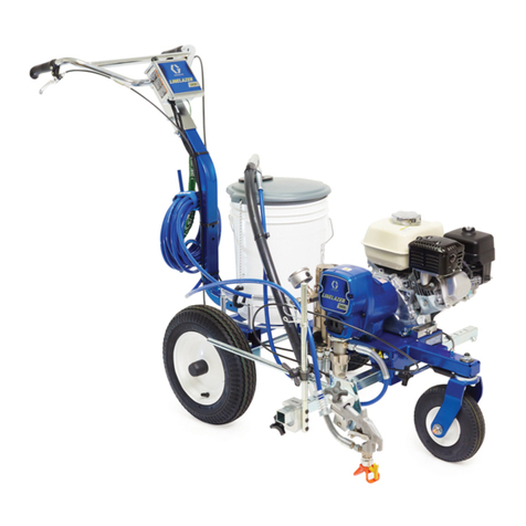
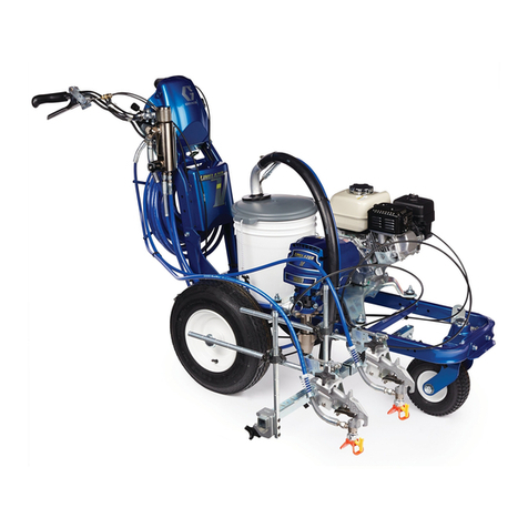
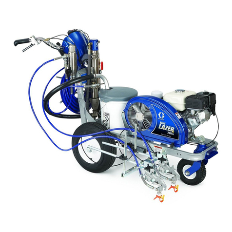
Graco Series A Operation manual

Other manuals for Series A

66

This manual suits for next models

3

Other Graco Construction Equipment manuals

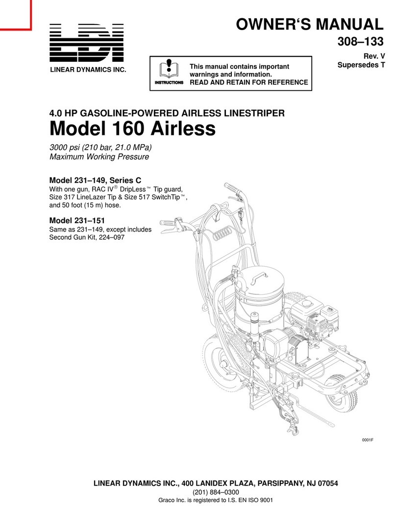
Graco LDI 160 Airless User manual

Graco

Graco LDI 160 Airless User manual

Graco LineLazer IV 250SPS User manual

Graco

Graco LineLazer IV 250SPS User manual

Graco ToughTek CM40 Instruction Manual

Graco

Graco ToughTek CM40 Instruction Manual

Graco LineLazer V 200HS Standard Series Instruction Manual

Graco

Graco LineLazer V 200HS Standard Series Instruction Manual

Graco LineLazer V 3900 17H449 Product guide

Graco

Graco LineLazer V 3900 17H449 Product guide

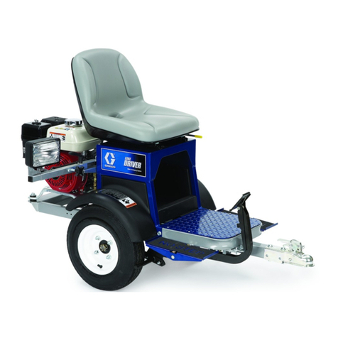
Graco Line Driver 233725 Operating instructions

Graco

Graco Line Driver 233725 Operating instructions

Graco LineLazer V 250SPS Instruction Manual

Graco

Graco LineLazer V 250SPS Instruction Manual

Graco LineLazer 3400 Instruction Manual

Graco

Graco LineLazer 3400 Instruction Manual

Graco 25M224 Use and care manual

Graco

Graco 25M224 Use and care manual

Graco LineLazer IV 3900 User manual

Graco

Graco LineLazer IV 3900 User manual

Graco LineLazer V 200MMA Use and care manual

Graco

Graco LineLazer V 200MMA Use and care manual

Graco 231-133 B Operation manual

Graco

Graco 231-133 B Operation manual

Graco GrindLazer 270 Operating instructions

Graco

Graco GrindLazer 270 Operating instructions

Graco LineLazer 130HS Instruction Manual

Graco

Graco LineLazer 130HS Instruction Manual

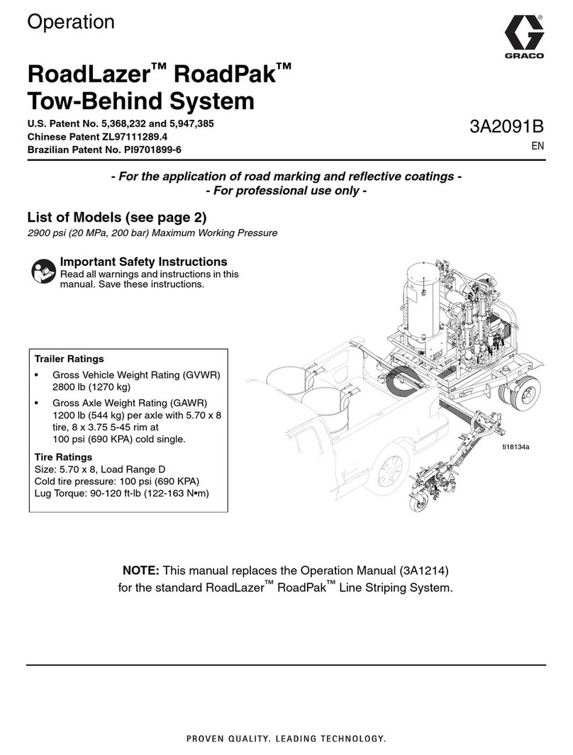
Graco RoadLazer RoadPak Guide

Graco

Graco RoadLazer RoadPak Guide

Graco LineLazer 3400 Use and care manual

Graco

Graco LineLazer 3400 Use and care manual

Graco Line Driver 233725 Instruction Manual

Graco

Graco Line Driver 233725 Instruction Manual

Graco EC140 Instruction Manual

Graco

Graco EC140 Instruction Manual

Graco 231-560 Operation manual

Graco

Graco 231-560 Operation manual

Graco LineLazer IV 250SPS Instruction Manual

Graco

Graco LineLazer IV 250SPS Instruction Manual

Graco Series A Operation manual

Graco

Graco Series A Operation manual

Graco LineLazer 3000 Operation manual

Graco

Graco LineLazer 3000 Operation manual

Graco LineLazer IV 3900 Use and care manual

Graco

Graco LineLazer IV 3900 Use and care manual

Graco RoadLazer RoadPak 24M143 User manual

Graco

Graco RoadLazer RoadPak 24M143 User manual

Popular Construction Equipment manuals by other brands

Ammann AV23-2 manual

Ammann

Ammann AV23-2 manual

stellar labs Model 7628 owner's manual

stellar labs

stellar labs Model 7628 owner's manual

Hailo H-50 manual

Hailo

Hailo H-50 manual

Greenlee 555RSC instruction manual

Greenlee

Greenlee 555RSC instruction manual

Manitowoc Grove CD3340B Service manual

Manitowoc

Manitowoc Grove CD3340B Service manual

Lux Tools A-FMR-20 Set manual

Lux Tools

Lux Tools A-FMR-20 Set manual

SIP 03683 manual

SIP

SIP 03683 manual

Volvo L30G Operator's manual

Volvo

Volvo L30G Operator's manual

Grizzly G8712 instruction sheet

Grizzly

Grizzly G8712 instruction sheet

Case DV201 Service manual

Case

Case DV201 Service manual

Wacker Neuson DT05 Operator's manual

Wacker Neuson

Wacker Neuson DT05 Operator's manual

HYVA AMCO VEBA 81 Series WARNING, OPERATING AND MAINTENANCE MANUAL

HYVA

HYVA AMCO VEBA 81 Series WARNING, OPERATING AND MAINTENANCE MANUAL

Atlas Copco Dynapac V5100TV manual

Atlas Copco

Atlas Copco Dynapac V5100TV manual

Manitowoc National Crane 1400A Operator's manual

Manitowoc

Manitowoc National Crane 1400A Operator's manual

SGS EC1500 owner's manual

SGS

SGS EC1500 owner's manual

Turbosol BM 30 Use and maintenance manual

Turbosol

Turbosol BM 30 Use and maintenance manual

Fayat CC424CHF instruction manual

Fayat

Fayat CC424CHF instruction manual

Altrad BELLE TDX 650A Operator's manual

Altrad

Altrad BELLE TDX 650A Operator's manual

manuals.online logo
manuals.online logoBrands
  • About & Mission
  • Contact us
  • Privacy Policy
  • Terms and Conditions

Copyright 2025 Manuals.Online. All Rights Reserved.

INSTRUCTIONS-PARTS
LIST
This manual contains IMPORTANT
WARNINGS and INFORMATION
G
308-105
REA0
AND RETAIN FOR REFERENCE
ORACO
Rev
A
LINE
LAZER-
GM
5000
.
'
3000
psi
(210
bar)
MAXIMUM
WORKlN
GASOLINE-POWERED AIRLESS
Model 231-133, Series
A
With
one
gun, RAC
lV@
Dripless"" Tip Guard,
Size
219
&
517 Switci-Tip" and
50
foot (15 m) hose
Same as 231-133, except includes
Model 231-141
Second Gun Kit, 224-097
NOTE:
This is an example
of
the DANGER label on your sprayer.
This label
is
available in other languages, free
of
charge.
See
page 47
to
order.
FIRE
AND
EXPLOSION
HAZARD
Spray painting, flushing or cleaning equipment
with
flammable liquids
in confined areas
can
resun in fire or explosion.
Use outdoors or in extremelyweli ventilated areas. Ground equipment.
Avoid all ignition sources such as static electricity from plastic drop
hoses, containers and objects being sprayed.
cloths.
open
flames such as pilot lights, hot objects such
as
cigarettes,
arcs from connecting or disconnecting power cords or turning light
switches
on
and
off.
Failure
to
follow this warning can result in
death
or serious injury.
,
I
SKIN INJECTION
HAZARD
~~ ~~ ~ ~~
Liquids
can
be
Injected into the bcdy by high pressure airless spray or
leaks
-
especially hose leaks.
Keep body oiear
of
the nozzle. Never stop leaks with any pall of the body.
Drain
all
pressure before removing
parts.
Avoid accidental triggering of
gun by always setting safety latch when not spraying.
Never spray without a tip guard.
In case
of
accidental skin injection.
seek
immediate
'Surgical Treabnent'.
Failure
to
follow this waming
can
result
in amputation or serious
iniuw.
I
READ
AND UNDERSTAND ALL LABELS AND INSTRUCTION MANUALS BEFORE USE
-
.,
GRACO INC.
P.O.
BOX
1441 MINNEAPOLIS, MN 55440-1441
@COPYRIGHT 1990, GRACO INC.
2
308-105
TABLE
OF
CONTENTS
TechnicalDa
ta
..................................
3
Caster Lever
&
Cable Operatlon
...................
21
Dimenions
3
operation
21
Warnings
Maintemnce
21
Caster tire replacement
21
English
......................................
4
Caster cable tension adjustment
:21
French
.......................................
6
Caster alignment
21
Spanish
......................................
8
HowToMountGun
.............................
21
Setup
........................................
10
Gun Cable
&
Dual Gun Selector ODeratlon
..........
22
...................................
.....................................
.................................
........................
................
..............................
Fueling
.......................................
~~
11
How the dual
gun
selectw
works
.................
22
Adjust the trigger cable tension
..................
22
Second
Gun and
Hose
Installation
.................
12
How to rel& the dual
gun
selector
cam
........
22
FluShing Guidelines
.............................
13
Whentoflush
13
..................................
Maintenance
................................
.
23
Howtoflush
.................................
13
Troubleshmting
................................
24
Startup
.......................................
14
Repair
or
Replacement
Spray
lip
&Tip Guard
16
Installation
16
Operation
16
Clearing a clogged tip
16
Maintenance
16
GasketSelection
16
..........................
Displacement Pump
26
Pressure Control
28
Pressure
Controi Calibration
29
Bearing Housing
&
Connecting
Rod
30
Drive Housing
31
Pinion HOUSing
32
Clutch
......................................
34
..........................
.............................
...................................
....................
...................................
.............
..........................
................................
.................................
..............................
..............................
Spray
lip
Selection
.............................
17
How
to
read a SwitchTip size
....................
17
Spray tip application recommendations
...........
17
SprayTechniques
..............................
17
Line Width Adjustment
.........................
17
Positioning the Gun Arm Assembly
................
18
Vertical position of the first or second gun
.........
18
Horizontal position of the first
gun
................
18
Horizontal position of the second gun
.............
18
Setup for spraying arcs
19
Mmt
guns
On
the
WIgifW
Side
Of
the
Cart
18
Adjust simultaneous
gun
triggering
................
19
Gun Arm Positions
..............................
20
.........
........................
Engine
........................
5.0
Horsepower. Honda
Maximum Working Pressure
............
3000
psi
(210
bar)
Cycles/Gallon (liter)
...........................
200
(53)
Maximum
Delivery
...............
1.25
GPM
(4.7
literlmin)
Fuel Tank Capacity
................
0.95
gallons
(3.6
liter)
Maximum
Tip
Size
.................
1
gun with
0.035
tip:
2
guns
with
0.025
tip
3
QunS
With
0.019
tip
Inlet Paint Strainer
16
mesh
(1190
micron)
Outiet Paint Filter
60
mesh
(250
micron)
Stainles
Steel
screen. reusable
Stainless Steel screen. reusable
Pump Inlet Size
...........................
3/4
npt (m)
Wetted
Parts
Fluid
Outlet
Size
1/4
npsm from fluid filter
Displacement Pump
.........
Zinc-Plated Carbon Steel.
Stainless Steel. Chrome-Plated Stainless Steel.
Polyethyiene. Tungsten Carbide. Leather. Polyurethane
Filter
.........
Zinc-Plated Carbon Steel. Stainless
Steel
...............
.................
...............
Engine
....................................
.35
Field
&
Wiring Hamess
........................
36
Clamp
......................................
37
Clutch Housing Removal
.......................
37
Reassembly
.................................
38
Displacement Pump Parts
......................
40
Pressure Control
Pam
.........................
41
Cart Pam
....................................
42
Gun Mounting
Parts
46
Mechanical Parts
44
PinlonParts
..................................
47
AcC~ssOri~
...................................
47
Warranty
...............................
Back Page
Parts
.............................
...........................
Weight (dry. Without packaging)
...........
237
Ib
(107
kg)
Height
...............................
40
in
.
(1016
mm)
Length
..............................
56
in
.
(1422
mm)
Width
................................
37
in
.
(940
mm)
'a
IMPORTANT
PHONE
NUMBERS
a
TO PUCEAN
ORDER.
contact your Gram distributor. or
call
this number
to
identify the distributor closest to you:
1-800-328-0211
Toll
Free
FOR
TECHNICAL ASSISTANCE
.
service remir information
or assistance regarding the appli&tion of Giaco equipment:
1-800-543-0339
Toll
Free
308-105
3
Thi5 equipment generates very
high
fluid pressure. Spray
from
General Safety
the gun, leaks or ruptured components can inject fluid through
yourskinandintoyourbody,andcauseextremeiyseriousbodl-
ly injury, including the need for amputation. Also, fluid injected
or splashed inta the eyes
OT
on
the
skin
can
cause
serious
damage.
NEVERpointthespraygunatanyoneoratanypartofthebody.
NEVER
put
your hand or fingers over the spray tlp. NEVER try
to
"blow back" paint; this is NOT an air spray system.
ALWAYS have the
tip
guard
In
place
on
the spray gun when
spraying.
ALWAYSfollowthePRESSURERELiEFPROCEDURE,
below,
before cleaning or removing the spray tip or servicing any sys-
tem equipment.
NEVER try
to
stop or deflect leaks with your hand or body.
Besureequipment safety devicesareoperating properly before
each use.
Medical
Alert--Airless Spray
Wounds
If
any
fluid
appears
to
penetrate your skin,
get
EMERGENCY
MEDICAL CARE AT ONCE. DO
NOT
TREAT AS A SIMPLE
CUT. Teii the doctor exactly what
fluid
was injected.
Note
to
Physiclam Injection
in
the
skin
is
a traumatic Injury.
DO
not delay treatment
to
research tox/c/w. Toxiciw is a
/tis important to treat the injury surgicallyas
soon
aspossible.
concern with Some exotic coatings injected directly into the
blood
stream. Consultation with a plastic surgeon or re-
constructive
hand
surgeon may
be
advisable.
Spray
Gun
Safety Devices
Be
sure all gun Safety devices are operating properly before
each
use.
Do
not
remove or
modlfy
any part
of
the
gun;
this
can
cause a malfunction and result In serious bodily Injury.
Safely
Latch
Wheneveryoustopspraying,evenforamoment,alwayssetthe
gun
safety latch
In
the closed or "safe" position, making the gun
inoperative.Failuretosetthesafetylatchcanresultinaccidental
triggering of the
gun.
Diffuser
The
gun
diffuser breaks
up
spray and reduces the risk
of
fluid
injection when the tip is
not
installed. Check diffuser operation
regularly. Follow the PRESSURE RELIEF PROCEDURE,
be-
'
low, then remove the spray tip. Aim the gun into a metal pail,
holdingthegunfirmlytothepail.Usingthelowestpossiblepres-
sure, trigger the gun. If the fluid emitted is
not
diffused into an
irregular stream, replace the diffuser immediately.
Tip
Guard
ALWAYS have the tip guard in place
on
the spray gun
while
spraying. The tip guard alerts you
to
the fluid injection hazard
and helps reduce, but does
not
prevent, the risk of accidentally
tip.
placing your fingers or any part
of
your body close
to
the spray
Always have the trigger guard
in
place on the gun when spray-
Trigger
Guard
lng
to
reduce the risk
of
accidentally triggering the gun
If
it
is
dropped
or
bumped.
Spray
Tip
Safety
the spray tip clogs while spraying, engage the gun Safety latch
Use
extreme caution when cleaning
oi
changing spray tips.
If
DURE, below, and then remove the spray tip
to
clean
It.
NEVERwIpeo~build-uparoundlhespraytipuntilthepressure
is fully relieved and the gun safety is engaged.
immedlately.ALWAYSfollowthePRESSURERELIEFPR0CE-
To'reduce the risk
of
serious bodily Injury, including
fluid
injec-
tion,splashingfiuidorsolventintheeyesorontheskln,orinjuly
from moving parts or electric shock, always foliow
this
proce-
dure whenever you shut
off
the sprayer, when checking or58rv-
icing any pan of the spray system, when installing, cleaning or
changing spray tips. and whenever you stop spraying.
1.
Engage the gun safety latch.
2.
Turn the ONlOFF switch
to
OFF.
3.
Flip the pressure control swltch to OFF.
4.
Disengage the gun safety latch. Hold a metal part of the gun
flrmlytothesideofagroundedmetalpail,andtriggerthegun
to
relieve pressure.
5.
Engage the gun safety latch.
6.
Open
the
pressure drain vaive,
having
a contalner ready
to
to
spray again.
catch the drainage. Leave the valve open until you are ready
7.
Disconnec! the spark plug cable.
/f
you suspect that the spray tip or hose
is
completelyclogged,
or that pressure has not been fully relieved after following the
Steps
above, wrap a rag around the
tip
guard retaining nut or
pressuregradually, then
loosen
completely. Nowciearthetipor
hose end coupling and
VERY
SLOWLY loosen the part
to
relieve
hose.
1
2
3
4
5
6
4
308-105
EQUIPMENT MISUSE HAZARD
2
General Safety
Any
misuse of the spray equipment or accessories. such
as
overpressurizing. modifying parts, using incompatible chemi-
calsandfiuids,orusingwomordamagedparts,cancausethem
to
rupture and result in fluid injection, Splashing in the
eyes
or
on the skin, or other serious bodily injury, or fire, explosion or
property damage.
NEVER alter or modify any part of this equipment; doing
so
could cause it
to
malfunction.
CHECK ail spray equipment regularly and repair or replace
wom or damaged parts immediately.
Always wear protective eyewear, gloves. CiOthing and respirator
as recommended by the fluid and solvent manufacturer.
System Pressure
This sprayer can develop 3000
psi
(210 bar)
MAXIMUM
WORK-
ING
PRESSURE.
&
sure all spray equipment and accessories
used are rated
to
withstand
the
this pressure. DO NOTexceed
the maximum working pressure of any component or accessory
used in the system.
Fluid and Solvent Compatibility
Ailchemicaisusedinthesprayermustbechemicailycompatibie
with
the wetted
Dam
shown in the
TECHNICAL DATA
on Daae
~~~~ ~
.
~ ~~
3.
Consult your chemical supplier
to
ensure compatibility.
-
~~ ~ ~
High pressure fluid in the hoses can be very dangerous.
if
the
hose develops a leak, split or rupture due
to
any kind of wear,
damage or misuse, the high pressurespray eminad from it
can
cause a fluid Injection injury or other serious bodily injury or
property damage.
ALLFLUIDHOSESMUSTHAVESTRAINRELIEFSONBOTH
ENDS!
me
strain reliefs help protect the hose
from
kinks or
bendsatorclosetothecoupiingwhichcanresuitinhoserupture.
TIGHTEN all fluid connections securely before each use. High
pressure fluid
can
dislodge a loose coupling or aiiow high pres-
sure spray
to
be
emitted from the coupling.
NEVER use a damaged hose. Before each use, check the elltire
hose for cuts, leaks, abrasion, bulging cover, or damage or
movemenl of the hose couplings.
if
any of these conditions ex-
ist,
replace the hose immediately.
DO
NOT try
to
recouple high
pressure hose or mend
it
with tape or any other device.
A
re-
paired hose cannd contain the
high
pressure fluid.
hoses
to
move equipment. Keep hoses clear
of
moving parts
HANDLE AND ROUTE HOSES CAREFULLY. Do
not
puli
on
and hot surfaces of the pump and gas engine. Do
not
use fluids
or solvents which are
not
compatible with the inner tube and
coverofthehose.DON0TexposeGracohosestotemperatures
above
180'
F
(82"
C) or below
-40"
F
(-40'
C).
Hose Groundlng Continuity
Proper hose grounding continuity is essential
to
maintaining a
grounded spray
system.
Check the electrical
resistance
of your
fiuidhosesatleastonceaweek.Ifyourhosedoesnothaveatag
on
it
whichspecifiesthe maximumelectricai resistance,wntaCt
the hose supplier or manufacturer for the maximum resistance
limits.
Use
a resistance meter
in
the appropriate range for your
hose
to
check the resistance.
If
the resistance exceeds the rec-
ommended limits, replace it immediately.
An
ungrounded or
poorly grounded hose
can
make your
system
hazardous. Also
read
FIRE
OR
EXPLOSION HAZARD,
below.
Aiwaysreadthechemicai
manufacturer'sliteraturebeforeusing
them in this sDraver.
Static electricity is created by the flow of fluid through the pump
and hose.
if
every
pan
of the spray equipment is
not
properly
grounded. sparking may occur, and the
system
may become
hazardous. Sparking may also occur when plugging in or un-
piuggingapowersUpplyCOrdorUsingagasoiineengine.Sparks
canignitefumesfromsoiventsandthefiuidbeingsprayed,dust
particles and other flammable substances, whether you are
spraying indoors or outdoors. and
can
cause a fire or explosion
and serious bodily injury and property damage.
using this equipment,
STOP SPRAYING IMMEDIATELY.
If
you experience any static sparking
or
any slight shock while
system again until the problem is identified and corrected.
Check the entire system for proper grounding.
Do
not
use the
Grounding
To reduce the risk of static Sparking. ground the sprayer and ail
other spray equipment used or located in the spray area.
CHECK your iocai electrical
code
for detailed grounding
in-
structions for your area and
type
of equipment. BE SURE
to
ground ail of this spray equipment
1.
Sprayer: for mobile spraying, be sure the grounding chain
contacts the ground. For stationary spraying, connect a
ground wire and clamp (supplied)
to
a true earth ground.
GASOLINE ENGINE HAZARD
~~~~~~~~~~~~~
NEVER
fill
the fuel tank while the engine is running or hot. Fuel
spiiied
on
a hot surface can ignite and cause a flre.
ALWAYS pourfuei in slowly
to
avoidspiiling. Also read
FIRE
OR
EXPLOSION HWRD,
above, and
FUELING
on
page 11.
gine exhaust is piped outside. The exhaust contains carbon
NEVER operate the engine in a closed building unless the
en-
cause serious illness and even death of inhaled.
monoxide, a poisonous. odorless and invisible
gas
which can
2.
Fluid hoses:
use
only
grOunded hoses with
a
maximum
Of
500
fl
(150
m)
combined hose length
to
ensure grounding
continuity.
See
Hose Grounding Continuity
above.
3. Spray
gun:
obtain grounding through connection
to
a prop
eriy grounded fluid hose and sprayer.
4.
Object being sprayed: according to
local
code.
5. Fluid supply container: according
to
local code.
6.
Allsolventpailsused whenflushing, aCCOrdingt0 iocai
code.
Use only metal
pails,
which are conductive. Do not
piace
the
pail
on
a
non-conductive surface, such as paper or card-
board. which intenupts the grounding continuity.
7.
To
maintain grounding continuify when flushing
or
relieving
pressure,aiwayshoidametalpartofthegunfirmlytotheside
of a grounded metal pail. then trigger the gun.
~~
Flushing Safety
Reduce the risk
of
fluid injection injury, static sparking, or
Splashing by following the flushing pr&eiluregivenon page 13
of this manual. Follow the
PRESSURE RELIEF PROCEDURE
on
page
4,
and remove the spray tip before flushing. Hold
a
and use the
lowest possible fluid pressure during flushing.
metal part of the gun firmly
to
the side
of
a grounded metal pail
United States Government safety standards have been adopted
underthe Occupational Safety and Health Act.
These
standards
-
particularly the General Standards, Part 1910, and the
Con-
struction Standards, Pan 1926
-
should be consulted.
308-105
5
Consignes
generales
de
sbcurltb
CetappareilproduitunfluideBtr~hautepression.Lefluidepul-
veriseparlepistoletoulefluidesouspressionprovenantdefultes
ouderupturespeutp4n&rersoulapeauouBI'int6rieurdumrps
et
entrainer des blessures tres graves, voir mirme une amputa-
tion. Mirme sans &re sous pression,
le
fluide Bclaboussant
ou
entrant dans
Ies
yeux
put
aussi entrainerdes blessures graves.
NE
JAMAlS pointer
le
pistolet vers quelqu'un ou vers une partie
quelconque du corps. NE JAMAIS menre
le
main ou lesdoigts
sur I'ajutage du pulverisateur. NE JAMAiS essayer de "refouler"
la peiniure.
Cet
appareil
Nest
PAS
un
compresseur
pneumatique.
TOUJOURS garder
la
protection de I'ajutage
en
place sure
le
TOUJOURS observer ia Marche
B
Sulvre Pour Detendre la
pistolet
pendant
la pulverisation.
Pression donnee plus loin, avant denenoyerou d'enleverl'aju-
tage
du
pulv6risaieur,
ou
d'effectuer
un
travail queiconque sur
une partie de I'appareii.
NE JAMAIS essayerd'arrirterou de devier ie fuites avec la main
ou
le
corps.
Avant chaque utilisation, bien s'assurer que
Ies
dispositifs
de
securite fonctionnent correctement.
Soins medicaux
En cas de penetration de fiuide
sous
la
peau: DEMANDER IM-
MEDIATEMENT
DES
SOINS
MEDICAUX D'URGENCE.
NE
PAS SOIGNER CETTE BLESSURE COMME UNE SIMPLE
COUPURE.
Avls
au mbdecln: La p6n6tration des fluides
sous
la peau
est
on
traumatisme.
II
est
Important de iralter chlrurglcale-
ment cette biessure Imm4dlatement.
Ne
pas retarder le
traltement pour effectuer des recherches sur ia toxlclt6. Cer-
tains revetements exotiques
sont
dangereusement towiques
haitable de consulter
on
chifurgien esth6tlques ou
un
chirur-
quand iis sont Injectbs directement dans le sang.
/I
est
sou-
gien sp6cialisb dans la reconstruction des mains.
Avant chaque utilisation, bien s'assure que
tous
les
dispositifs
Dispositifs
de
securlte
du
pistolet
de skurite du pistolet fonctlonnent correctement. Ne pas
enle
verni modifierune partiequelconque dupistolet; ceci risquerait
d'entrainerun mauvaisfonctionnement
et
des blessuresgraves.
Verrou de s6curit6
A
chaaue fois aue l'on s'arrirte de Dulvbriser, meme s'il s'agit
d'un
court instant, toujours menre ievemu desecurite
du
pisto-
let sur la position, 'fermW ou "s6curit6" ("safe"), pour em@-
cher
ie
pistolet de fonctionner.
si
le
verrou de SecUrlte West
pas
mis,
le
pistolet
put
se
declencher accidentellement.
Diffuseur
LediffuseurdupistoletsertBdiviseriejetetBreduirelesrisques
d'injectionaccidenteliequand
I'ajutagen'est
pasen
place.Veri-
fierlefonctionnementdudiffuseurreguli8rement.PourcettevB-
rification, detendre ia pressionenobservant la Marche
z+
SUiVre
Pour Detendre
la
Pression donnee
pius
loin
eniever I'ajutage
du pulverisateur. Pointer
le
pistolet dans un
mu
en
metal.
en
le
maintenant fermement contre
le
seau.
puis,
en
utilisant ia
tolet. Si
le
fluide projete n'estpas diffuse sous forme de
jet
ime-
pression la plus faible possible. appuyersur la gachette du
pis-
gulier. remplacer immediatement
le
diiseur.
Protection
de
I'ajutage
TOUJOURS maintenir la protection de I'ajutage en place sur
18
pistolet du pulverisateur pendant la pulverisation.
La
protection
de I'ajutageattire I'attention surles risquesd'injection ietcontri-
bue
B
reduire. mai n'evite
pas
ie risque, que ies doigts Ou
une
partie queiconque
du
corps
ne
passent accldentellement
B
proximite immaiate de I'ajutage du puiverisateur.
Consignes
de
securlte
concernant
I'ajutage
du
pulvbrlsateur
Faire extrhement attention
B
I'occasion du nenoyage ou due
remplacement des ajutages du pulverisateur. Si i'ajutage
se
bouche pendent ia pulverisation, menre lmmediatement lever-
roudes6curitedupistolet.TOUJOURSbienobserveiaMarche
B
Suivre Pour DBtendre la Presslon puis enlever i'ajutage
du
pulverisateur pour
le
nenoyer.
du pulverisateur avant que
la pression ne soit completement
NE JAMAIS essuyer ce qui
s'est
accumule autour de I'ajutage
tombee
et
que ie verrou de securite du pistolet
ne
soit engage.
MARCHE
A
SU~VRE
POUR
DETENDRE
LA
PRESSION
~~~~~~~~~~~~~~~~~~~~~~~~~~~~~,~~~~~~
Pourreduire
Ies
risquesde blessuresgraves,
y
compris lesbies-
sures par projection de fluide ou celies causees par de &a-
contre le cbte
d'un
seau en metal, actionner
le
pistolet pour
libkrer la pression.
boussuresdansles yeuxou surla peau, pardespiecesen mou-
5,
verrou
de
s6curite
du
pistolet,
fois
que
i'on arrirte ie pulverisateur,
B
I'occasion de ia vbrifica-
6.
Ouvrir la soupape
de
securite
et
la
laisser ouverte jusqu'h ce
vement, toujours bien observe
cene
marche
B
suivre chaque
tion,
du
hale
w
du
nenoyage
du
systbme ou lors du Change
ment des ajutages.
que
1.017
soit prirt
A
se
servir de nouveau du pulverisateur.
3
.,
?An,.*
,,..,,.
,.*.*,*A
...,,
7.
Debrancher ie
fil
de la
bouaie.
1.
Engager
le
verrou de &curite du pistolet.
2.
Menre
le
levier d'arr6t du moteur sur ARRET (OFF).
Si
I'on
soupconne
que
le
tuyau
ou
Ibjutage est cornpletement
3.
Bascuier I'interrupteur de commande de pression sur
AR-
'
apres avoir procede aux op6rations ci-dessus. desserrer TRES
bouch6
ou
que la pression n'e pas et6 complbtement llb6r6e
4.
Desengager ieverrou desecuritedu pistoiet.Tout
en
mainte- de la protection de I'ajutage et liberer progressivement la
LENTEMENTunraccorddeboutdetuyauouI'~crouderetenue
-
RET
(OFF).
nant une partie metallique
du
pistolet fermement appuye pression.
3
4
5
6
6
308-105
R~SQUES EN CAS DE MAUVAlSE UT~L~SAT~ON DU
MATERIAL^^^^^^^^^^^^^^^,^^^^^^^^^^^^
Tome utilisation anormaie de i'appareii
du
puiverisation
w
des
Ce
puiverisateur
put
produire
urn
PRESSION
MRYMUM
DE
Consignes generales de securIt6 Presslon
accessoires comme, par exemple. la mise
sous
une pression
TRAVNL
210
bar(30w Iblpo.2) S'assurerquetous ieseiements
chimiquesetdematieresincompatibieseti'utiiisationdepieces
lapressi0nmaximumdetravaildecepuiveri~teur.NEPASd~-
excessive,
Ies
modifications de
pihes,
I'utiiisation de produits du puiverisateur
et
ses
accessoires
sont
conGus
pour resister
B
U&S
w
abimbs
paut
causer
des
d&%ts
B
I'appareil ou des
passerlapressionrnaximumdetravaiid'aucundes~i~mentsw
ruptures
de
pieces
et
entrainer une injection de iiquide ou
d'au-
accessoires utilisffi avec
cet
appareii.
tres biessuresshrieuses. un incendie, uneexpiosionoud'autre
Compatibilite chimlque des
corps
d&g&ts. BlEN S'ASSURER que tous
185
corps
des solvants utiiises sont
Toujoursporteruneprotectionpouriesyeux,degants,desvh-
chimiquementcompatiblesaveCiespartiesmouili~esindiqu~es
mens protacteur
et
un
dispositif pour
la
respiration correspon-
dansles'Oonn~stechniques",Bpage3.Toujousliresoigneu-
soivants.
dam aux recommandations des fabricants de fluides
et
sement
Ies
documents
et
brochures du fabricant
des
fluides
et
soivaniSutilis6s avant
de
s'en
sewirdans ce pulv6risateur.
MESURES
DE
SECURlTE CONCERNANT LES TUYAUX FLEXlBLES
~~~~~~~~~~~~~~~*~
LefluideBhautepressioncircuiantdanslestuyauxpeuthtretr8s
dangereux.EncasUefuftesurietuyau,deRssure,dechirureou
sation,
ies
projections
de
fiuide haute pression
qui
en
provim
rupture
B
la suite de i'usure, de d&g&ts ou d'une mauvaise
utili-
nent peuvent entrainer des blessures graves par penetration
sous la peau ou
par
contact, ainsi que des d6g&ts matbrieis.
TOUS LES TUYAUX FLEXIBLES DOIVENT
AVOlR
DES RES-
SORTSSPIRALEDE PROTECTIONAUXZ BOUTSI
Lesspira-
les
de
protection contribuent
d
&iter fa formation
de
plik,
de
boucles ou de nC8uds sur ies tuyaux qui pourraient entrainer la
rupture du tuyau
B
i'endroit du raccord ou
a
son voisinage.
tion. Lefiuidesouspression putfaire sauter un raccord desser-
r6ouproduireunjetBhautepressions'echappantparleraccod.
NE JAMAIS utiliser
un
tuyau endommage. NE PAS essayer de
refaire
le
racMrU
d'un
tuyau haute pression
ni
de
reparer
le
tuyau avec
du
ruban adheslf ou partout autre moyen. Un tuyau
rem& ne
wut
pas
&sister au fluide sous Dression.
SERRER FERMEMENT
tOUS
ies raccords avant chaque
UtiliSa-
MANiPULER LES TUYAUX AVEC PRECAUTION
ET
CHOlSlR
SOiGNEUSEMENT
LEUR
CHEMIN. Ne
pas
depiacer ie fiuide
entirantsurletuyau.Nepasutiliserdefluidesoudesoivantsque
nesontpascompatibiesaveci'enveioppintBrieurouexterieure
detuyau.NEPASexposerletuyauBfiuidesdestemperaturessu-
p8rieuresB82'C (180'F)ou inferieuresd -40°C
(-40'F).
Continuit6
de
la mise
a
la terre des tuyaux
tieliepcurmaintenirlamiseBiaterredei'ensembiedevaporisa-
Une bonne continulte de la mise
B
la
terre
des tuyaux
est
essen-
tion. Vbrifiez ia rffiistance eiectrique de vos tuyaux
d
fluides
el
a
air, au moines une fois par semaine. Si vdre tuyau ne compor-
tepasd'etiquettequi
pr&iselar&istanceelectrique
maximum,
prenez contact avec ie fournisseur de tuyaux ou la fabricant
de
resistance
de
ia gamme appropriee pour Mtre tuyau
et
veri-
pour avoir Ies limites de resistan- maximum. Utilisez un m&e
fiez la rkistance. Si celle-ci depasse ies iimites recomman-
dees. remplacez ie tuyau immediatement. Un tuyau sans mise
B
ia terre
ou
avec une mise
A
ia terre inmrrecte mut entrainer
.~
~ ~
des
risques pour votre systeme. ~lsez
au&
LES
RISQUES
D'INCENDIE
OU
D'EXPLOSION.
,
"~
~
De
I'Biectricit8 statique
est
produite par
le
passage
du fluide
B
grand0 vitese dans la pompe
€3
dans
les
tuyaux. Si
toutes
ies
pieces de I'appareil de pulverisation ne sont
pas
convenable.
ment reiiees ou
a
ia masse ou
B
ia
terre. des Btincelles peuvent
se
prcduire
e!
i'appareii risques dUtre dangereux.
Des
elincei-
Ies
peuvent Egalement
se
produire
B
i'occaslon
du
branche
tilisation d'un moteur
B
essence. Les Btinceiies sont suffisantes
ment
ou
du dbbranchement du cordon d'ailmentationoude
I'u.
pour allumer ies vapurs de solvants et ie fiuide puiverise,
leg
fines panicules de poussiere ainsi que d'autres substances
in.
flammables, quand on pulv6ris6
B
i'interieur ou
a
I'exterieur,
et
eiies peuvent causer un incendie ou une explosion, ainsi que
des biessures graves
et
des
d6gk
matBriels.
S'ilseproduitdesgtinceilesd'Ble~ricit8statique,ousivousre~
Sentez
la
moindre decharge, ARRETE2 IMMEOIATEMENT
LA
PULVERlSATfON. Verifiez que
le
systeme avant que
le
probl6.
me
soit
identifie
et
corrig6.
Mlse
B
la
terre
ou
la masse
Pour reduire ies risques
de
production d'Btinceiies d'eiectricite
statique. ie puiverisateur et tous
les
Qquipement utiiises ou
se
trouvant
dam
ia
zone
de pulverisation doivent &re rei&
h
later-
re ou
B
la
masse. Pour connaitre
le
detail des instructions
de
miseB1aterredanslar~ionetletypepa~icuiierd'~quipement.
CONSULTER
le
code ou
les
reglementations electriques
iwa-
vants sont bien relies
B
ia
terre:
les.
S'ASSURER que
tous
le
equipments de puiverisation sui-
1.
Pulvbrisateur: Relier
le
file de masses
et
le
wilier (foumi)
A
une
brine
terre.
2.
PistoletRealiser ia mise
B
la
terre
en
le
ramrdant
d
une
tuyaufiexibleet~unepuiv~risateurd~j~convenabiementre-
lies
B
la terre.
3.
Tuvaux flexibles: Afin d'assurer ia continuit6 de
la
mise
A
ia
teire,n'utiliserquedestuyauxcomportantunemisediaterre
et ayant une longueur maximum combinhe de
150
m (1500
piads).
Se rewrter kalement
au
DaraaraDhe, "Continuit6
"."
~ ~
..
.~.
-
.
~ ~
.-
.~
.
du
clrcult
de
mis
B
IS
terre
des
tuyaui".'
tations locales.
4.
Recipient dalimeniation: observer
ie
ccde
ou
ies rbglemen-
5..
Objets,
mat~rielousu~acesrecevantlapulv~risation:
obser-
vex
le
code
ou
les
r4giementations
locales.
6.
Tous
le
seaux
de
solvant
utilis4s pour
le
rinpge: ObSeNer ie
code ou Ies rbgiementations
locales.
Nuiiliser que
des
seauxmbtallique conducteurs de l'Biectricit6.
Ne
pas mettre
le
s~au
sur une surface non conductrice comme sur du
pa.
pier ou du carton car cela interromprait la continuite
de
la
mise
B
la terre.
7.
Pour consewer
la
coniinuitti de
la
mise
i)
la ierre
quand
on
rincb
le
rnat6riel
00
quand
on
libere
la pression. toujours
puy6e contre ie
cBt8
d'un seau
en
metal puis appuyer sur
ia
maintenir une partie metaiiique du pistolet fermement
ap
detente
du
pistolet.
Mesures de Sbcurlte concernant le RinGage
et
les
risques
dOs
aux Btincelies d'biectricit6 statique
ou
aux
PourreduireiesrisquesdeblessuresparpWtrationdeiapeau
Bciaboussures. observe la marche
B
suivre pour
le
rinGage don-
&e
&
ia
page
13
de
ce
manuei.
Seguridad
general
Esteequipogeneralunfluidoaunapresi6nmuyalta.Elrociado
de ia pistola.
10s
escapes de fluido
0
roturas de
10s
componen-
tes pueden inyectar fluido en la piel y
e1
cuerpo y causar iesio
nes extremadamente graves, inciuyendo a veces la necesidad
deamputaci6n.Tambien, el fluido inyectado osalpicado en
los
ojos
puede causar graves daiios.
NUNCAapuntarlapisIolahaciaalguienoalQunapartedeicuer-
po.NUNCAcolocarlamanooiosdedosencimadelaboquilla.
NUNCAtratarde"hacerretornarlapintura";esteNOesunsiste-
ma de rociado
de
alre.
SIEMPREtenercolocadoelprotectordelaboquillaenlapistola
mientras
se
est8 pulverizando.
SIEMPRE
seguir ei procedimiento de descarga de preslbn,
dado
mhs
abajo, antes de limpiar
o
sacar la boquiila
o
de dar
sewicio a cualquier del sistema.
NUNCA tratar de parar
o
desviar
10s
escapes
con la mano
o
e1
cuerpo.
Asegurar que todos
10s
aparatos de seguridad del equipo esthn
funcionando bien antes de cada uso.
Tratamiento
medico
Si oareciera aue un wco de fluido mnetr6 ia Diel. conseouir
TRATAMIENTO MEDICO
DE
URGENCIA
DE INMEDIA~O.
NO TRATAR
LA
HERIDA COMO
UN
SIMPLE CORTE. Decir
ai medim exactamente cua fluido fue.
Avlso a/ rnhdlco:
Si
se
llega a inyectar esta fiuido
en
la pie!
se
causa
una
lesidn traumatica. ES Importante tratar qulrbr-
glcamente
la
Ieslbn
8
la brevedad posible.
No
demorar el
tratamiento para investigar la toxicidad. La toxicidad
es
aigo
de Sumar impoftancia
en
elgunas pinturas exdticas cuando
se inyectan directamente a1 torrente sanguineo. Sirs conve-
niente consultar a
un
especialista
en
cirugia pidstica
o
re-
constfuctiva de
ias
manos.
PROCEDIMIENTO DE DESCARGA
DE
PRESION
yendo
ia
inyecci6n de fluidos, salpicaduras en
10s
ojos
o
ia piel,
Parareducirelriesgodesufrirgraveslesionescorporales,inclu-
este procedimiento
al
apagar
la
maquina pulverizadora, al revi-
o
Iesiones causadas por piezas en movimiento, siempre seguir
sar, ajustar
o
limpiar
el
sistema,
o
al
cambiar
las
boquiiias.
2.
Mover
el
interruptor de parada del motor a
OFF.
1.
Enganchar
e1
pestillo de seguridad de
la
pistola.
3.
Mover
el
intenuptor de Control de presi6n
a
OFF.
4.
Desenganchar
el
estillo de seguridad de la pistola. Mante-
neruna pane met&icade
la
pistola firmementecontra ei lado
de un balde de metal
y
activar la pistola para descargar
la
presi6n.
Aparatos
de
segurldad
de
la
pistola
pulverlradora
Asegurar que todos ios aparatos protectores de la pistola esffin
funcionando bien antes de cada
uso.
No sacarni modificar nin-
guna pie= de la pistoia pues podria causar
el
malfunciona-
miento de la misma con las consiguientes lesiones personales.
Pestillo
de
seguridad
Cada vez que
se
deje de pulverizar, aunque sea por
un
breve
cion "cerrada",
lo
que deja la pistola inoperante. El no hawrlo
momento, siempre colocar
el
pestilio de seguridad en la
mi-
puede llevar al disparo imprevisto de la pistola.
DiFusor
el riesgo de inyecci6n cuando no est8 instalada la boquilla.
Re-
El
difusor de la pistola dispersa
el
chorro pulverizado y reduce
visar con regularidad
el
funcionamiento del difusor. Seguir
el
procedimlento de descarga de preslbn, dado
mas
abajo, y
despues sacar la boquilla. Apuntar la pistola
a
un balde metali-
co,sosteniendolabienfirmecontra~I.Utilizandolapresi6nm8s
bajo
posible, disparar la pistola. Si
el
fluido emitido
no
sale dis-
persoenunchorroirregular,rwmplazardeinmediatoeldifusor.
Protector de
la
boquiNa
SlEMPREtenerelprotectordelaboquillacolocadoenlapistola
contra
el
peligro de inyecci6n y ayuda a reducir, per0
no
evita,
mientras
se
est6 pulverizando. Este protector llama la atencion
cuerpo cerca de la boquilla.
la colocacion accidental de
10s
dedos
0
cualquierotra parte del
Segurldad
de
la
boqullla
pulverlzadora
Tener mucho cuidado al limpiar
0
cambiar la5 boquillas. Si
lle-
till0 de
la
pistola de.inmediato. SIEMPRE seguir
el
procedl-
garaaobstruirse
mientrasestdpulverizando,engancharelpes-
mlento de descarga de preslbn y despues scar
la
boquilla
para limpiarla
quillaantesdequesehayadescargadoporcompletolapresi6n
NUNCA limpiar la acumulacion de pintura airededor
de
la
bo-
y
el
pestillo este enganchado.
6.
Abrirlav8lvuladealiviodepresi6nydejarlaabieRahastaque
se
este
nuevamente list0 para pulverizar.
7.
Desconectar
si
cable de la bujia.
Si
se
sospecha que la boquilla
0
la manguera est6 compieta-
presidn despu6s
de
haber seguido
el
procedimiento anterior,
mente obstruida.
o
que
no
se ha descargado por cornpieto la
aflojarMUYLENTAMENTEunadaDtadordeextremodelaman-
guera
0
la tuercade renenci6n del'protector de lay punta
y
des-
cargar gradualmenle la presion.
1
2
3
4
5
6
0
308-105
Seguridad general
Cualquier mal uso del equipo pulverizador
o
10s
accesorios.
tal
Esta pulverizadora puede desarrollar 210 barias
(3000
psi) de
como sobre presurizacibn, modificaci6n de piezas, us0 de ma-
PRESlON
DE
TRABAIO
MAXIMA.
Asegurar que todo
el
equipo
teriales y productos quimicos Incompatibles,
o
utilizaci6n de pulverizador y sus accesorios tienen la capacidad para aguan-
piezasdahadasodesgastadas,puedehacenqueserompany
tarlapresi6nmtiximadetrabajodenlng~ncomponenteoacce
causen ia inyecci6n de fluido
u
otras
lesiones
oorporales
gra-
sori0 de
este
sistema.
yes.
incendio. explosl6n
o
dahos a ia propiedad.
Siempre usargafas, guantes, VeStimentaS
protector as^
un res- Siempre leer
las
instNccionesdelfabrlcante
delfluido
y
solven-
piradero. tal como recomiendan
10s
fabricantes del fluid0
Y
del
te
antes de usarlos
en
esta pulverizadora dadas en la pagina
3.
solvente.
Pres1611 del slstema
Compatibllidad de fluido
Eifluidoqueescapaaaltapresi6nporlasmangueraspuedeser
MANEJARY PASARCUIDADOSAMENTE LASMANGUERAS.
mtura
0
rajadura debido
a
cualquier
tip0
de desgaste. dano
0
o
soiventes que Sean incompatibles con
el
tub
interno y la cu-
muy peligroso. Si en la manguera
se
desarrola
un
escape,!na No tirarde
las
mangueras para mover
el
equipo. No usarfluidos
una
lesion por inyeccion u otras lesiones corporales graves
0
ras sobre
82"
C (18O'F)
o
bajo -40°C
(40°
F).
maltrato.
el
Chorro
a
alta presi6n emitido por alii puede causar bierta de la manguera. NO expner
las
mangueras atemperatu-
dahos a la propiedad.
TENER GUARDAS DE RESORTE EN AMBOS EXTREMOSI
lTODAS
US
MANGUERAS PARA FLUIDOS TIENEN QUE
Estas protegen las mangueras contra dobleces
0
retorceduras
enlosacoplamientosocercadeelios,losquepdriantraduclr-
se
en
roturas de la manguera.
Antes de usarlas. APRETAR bien firmes todas ias conexiones.
El fluido a lata presion puede desalojar un acoplamiento
Suelto
o
dejar que pro
BI
escape
un chorro a alta presi6n.
Continuidad del circulto de puesta a tierra
de la manguera
Lacontinuidaddelcircuitodepuestaatierraapropiadoesesen-
cia1 para mantener conectado a tierra
el
sistema pulverizador.
Es Indispensable revisar la resistencia eiectrica maxima de laS
Si
la manguera
no
tiene una etiqueta
en
la cual
se
especifica
la
manguerasdeaireydefluidopriomenosunavezalasemana.
veedor
o
fabricante de la manauera mra
la
informaci6n sobre
resistencia electrica maximum. ponerse en contact0 con
el
prc-
NUNCAusaruna
mangueraqueestadahada.Siemprerevisarla
10s
limltesde resistencia. Usark meirode resistencia
en
lag&
en busca de cortaduras, escapes, abrasion, cublerta abultada. ma apropiada para comprobar
la
resistencia;
si
excede
10s
lites
o
acoplamientos sueitos
o
dahados. Si ilegara
a
encontrarse recomendados, reemplazarla de inmediato.
Es
muy arriesgado
cualquiera de estas condlciones, reemplazar de inmediato
la
tener una manguera sin puesta a tierra
0
con la puesta
a
tierra
manguera.
NO
intentar reacoplaruna mangueradealtapresi6n
enmalascondiciones.Leertambi~niainformaci6nsobreRIES-
o
enmendarla con cinta adhesiva
u
otro material similar. Una
GO
DE INCENDIO
0
EXPLOSION.
m&
arriba.
manguera que ha sido remendada no aguante
e1
fluido a1 alta
presi6n.
PELlGRO DE INCENDlO
0
EXPLOSION
~~~~~~~~~~~~~~~~~~~~~~~~~~~~~~~~~~~~~
guera crea electricidad esttitica. Si todas las partes del equipo
El flujo a alta velocidad del fluido al pasar por la bomba y man-
2.
Mangueras para fluidos: usar solamente mangueras con
pulverizador
no
tienen buena tierra, pueden ocurrir chispas,
puesta a tierra de una iongitud combinada de 150
m
(500
pies), para asegurar buena continuidad a tierra. Referirse
conviniendo al sistema
en
algo peiigroso. Tambien, pueden
producirse chispasal enchufar odesenchufar
e1
cordon elbctrl-
tambien al Mrrafo sobre continuidad a tierra de
la
co
o
al usar un motor de gasolina. bras chispas pueden infia-
3.
Pistoia: hacer
la
puesta a tierra conectlndola a una mangue
manguera.
do, particulas de polvo y otras sustanclas inflamables,
sea
al
4.
Suministrar
un
recipiente: de acuerdo al c6digo local. Usar
mar
10s
vapores de
10s
solventes y
e1
chorro de fluido pulveriza- ra de fluido y pulverizadora bien conectadas a tierra.
aire libre
0
bajo
techo, io que podria causar una explosion
o
ln- solamente baides
de
metal, que Sean conductivos. No
MID
cendio y graves lesiones corporales
y
dah
a
la
propiedad. car ei balde en una superflcie no conductiva, como papel
o
SI
ocurre una chispa de electricidad estatica
o
incluso un ligero
5.
objeto que se est4 rociando: de conformidad
con
el
c&igo
cartbn, que intemmpe la continuidad a tierra.
chcque electrico mientrasse usa
el
equipo, DEJAR DE PULVE-
REAR
DE
lf"DIATo. FkVisar todo
01
Sigema en busca de
6.
Todos
/os
baides de soivente usados durante e1 lavado, de
local.
una tierra apropiado. No usar de nuevo
el
sistema hasta haber
identificado y solucionado
el
problema. conformidad con
e1
&dig0
local.
7.
Para mantener
la
continuidad
a
tierra durante
e/
lavado
o
Puesta a tlerra
descarga de presih, siempre apoyar una parte melalica de
Para reducir
e1
riesgo de chispas staticas. conectar a tierra la
lapistolabienfirmewntraelcostadodebaldedemetal,des-
pulverizadora y
tcdo
el otro equipo de pulverizar que
se
use
o
pubs apretar
el
gatillo.
seencuentreenellugarquesevaarociar.CONSULTARelc6di-
SeWdad durante el lavado
go electric0 de la localidad para las inStNccioneSs&re laSCm para reduck
el
riesgo de que
se
lnyecte
0
salpique fluid0 en la
nexionesatierraexlgidasparalazonaytipodeequipo,~~~~~-
Piel, oque ocurra unadescarga de electricidad estatica,siem-
RAR
de conectar a tierra
tcdo
este
equipo.pulver1zador: pre seguir las INSTRUCCIONES PARA EL LAVADO, dadas en
1.
Puiverizadora: Conectar
e1
alambre de tierra y
la
abrazadera
si6n
en la ptigina
8.
y quitar la boquilla de metal y usar
le
pre-
la
ptigina
13.
Seguir
el
procedlmlento de Uescarga de pre-
(suministrada) a una buena conexi6n a
tiwa.
si6n
mhs
baja posibie
de
fluido durante
e1
lavado.
PRECAUClONES PARA LOS MOTORES DE GASOLlNA
j~~~~~~~~~~,~~~~~~~:~~;?.~~~.?~:~~~:~~~:~~~~
,.~,,~~.
................................................
.,.,
:.:.~:~~:~.,.~:~~::~:::.:
.,.,
~~~.::~~::.~:~:;!~~~~.~~.:~?~~~~~~;?~~~~.~~.:~
NUNCA llenar el tanque de combustible mientras
e1
motor
esta
NUNCA hacerfunclonar
e1
motor en
un
edificio cerrado sin en-
funcionando
0
callente. El combustible derramado en una su- caminar
10s
gases de escape hacia
el
aire libre. Los gases de
pedicle callente puede encenderse y provocar un incendio. escape contienen monoxido de carbono, un gas venenoso, sin
SIEMPRE verter
el
combustible lentamente para evitar derra-
oloreinvislblequepodriacausarenfermedadesgraves,
incluso
mes. Leer
PELIGRO DE INCENDIO
0
EXPLOSION.
ia muerte. a1 inhalarse.
308-105
9
1.
2.
Read and follow the warnings
on
pages
4
and
5
before installing or operating this sprayer.
Unpack the Llne Lazer. Carefully raise the handle
(19)
to averticai position. Four screws
(39)
and iock-
nuts
(40)
are packed
in
a bag. Install the
two
rear
screws
(39A)
and finger tighten the nuts
(40A).
lnstaii
one screw
(398)
and nut
(408)
on each side of the
handle. Firmly tighten all four nuts. See Fig
10-1.
are caught on the frame or become kinked.
3.
To
install a second
gun
and hose, see page
12.
4.
Fill the packlng nut/wet-cup
(216)
1/3
full
with
Graco Throat Seal Liquid (TSL), supplied, and keep
It
filled, to help extend the pump life. See Fig
10-2.
5.
Check the engine
oll
level. Refer to the Honda en-
mation: Remove one ofthe oil fill plugs; the oil should
gine manual, supplied.
This
Is
a summary of the infor-
be airnost overflowing.
See
Fig
10-2.
Add oil as
necessary.
Also
readthe MAINTENANCE section on
page
23.
Recommended engine oil: Use a high-quality, deter-
gent oil,
SAE
IOW-40,
classified “FOR
SERVICE
SE
or
SF”.
6.
Be sure your system
Is
properly grounded before
operating It. The grounding chain connected to the
tion. if you use the unit for stationary spraying, con-
cart must contact the ground at all times during opera-
nect the grounding clamp (1
59)
to a true eaflh ground.
Read and follow FIRE
OR
EXPLOSION HAZARD on
page
5.
7.
Fill
the gas tank.
See
FUELING
on
page
11.
I
8.
Flush the pump to remove the lightweight oil which
was
left
in
the pump to protect it from rust. Follow the
FLUSHING GUIDELINES on page
13.
9.
Prepare the paint according to the manufacturer’s
recommendations. Remove any skin that may have
formed. Stir the paint to mix pigments.
Strain the paint through afine nylon mesh bag (avaii-
could clog the filter or spray tip. This
is
probably the
able at most paint dealers) to remove particles that
most important step toward trouble-free spraying.
Fig
10-1
ENGINE
OIL
FILL
PLUG\
Fig 10-2