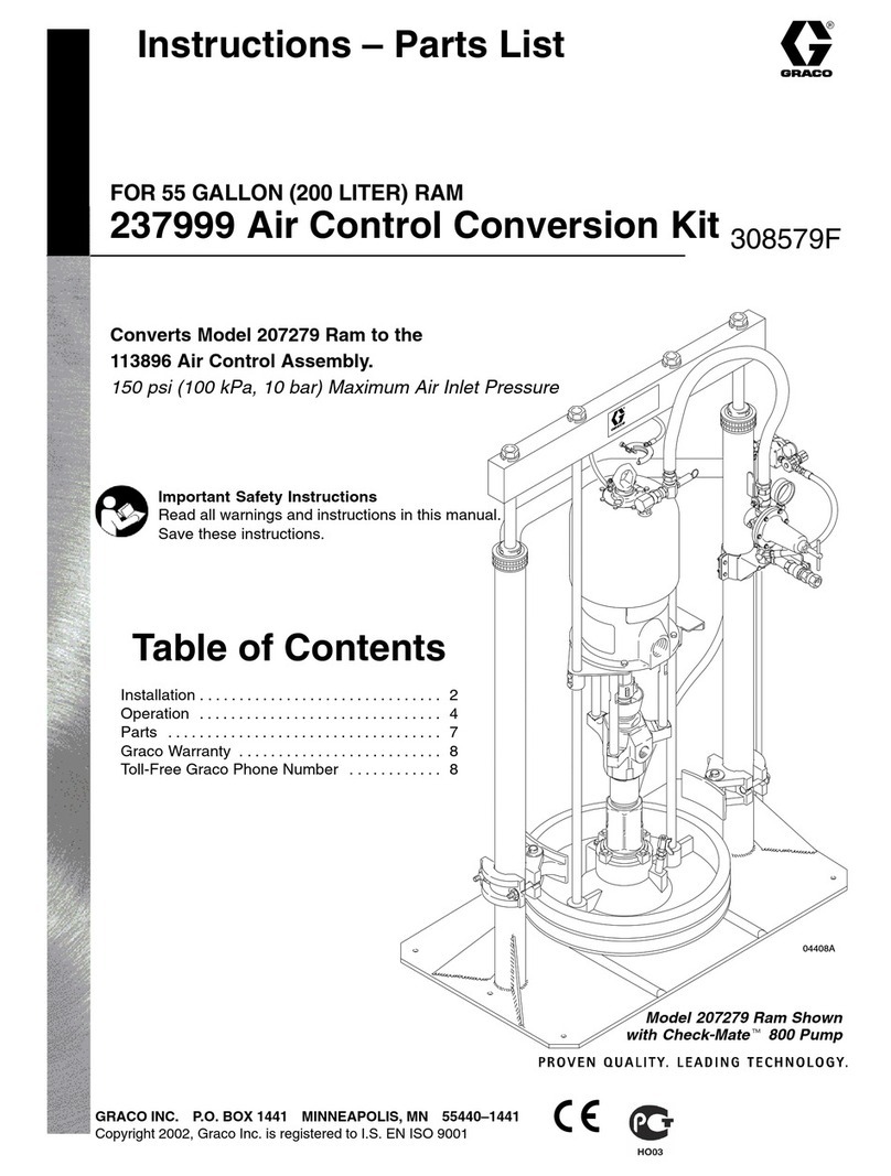
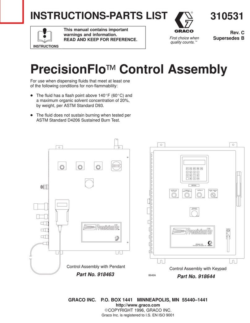
Graco 25A693 User manual

Instructions
Intelligent Intelligent
IntelligentPaint Paint
PaintKitchen Kitchen
Kitchen3A4030C
EN
Used Used
Usedto to
toremotely remotely
remotelymonitor monitor
monitorand and
andcontrol control
controlequipment equipment
equipmentused used
usedin in
ina a
apaint paint
paintkitchen. kitchen.
kitchen.For For
Forprofessional professional
professionaluse use
useonly. only.
only.
Important Important
ImportantSafety Safety
SafetyInstructions Instructions
Instructions
Readallwarningsandinstructionsinthismanualandallrelated
manualsbeforeusingtheequipment.Save Save
Savethese these
theseinstructions. instructions.
instructions.
TouchscreenBoxandSupervisorBox
componentsshown.
PROVENQUALITY.LEADINGTECHNOLOGY.

Contents Contents
Contents
ControlComponents.............................................2
ComponentManuals.............................................3
Warnings.............................................................4
IntelligentPaintKitchenOverview..........................7
InstallationandWiring.........................................25
SoftwareSetup...................................................44
TouchscreenSoftware........................................57
NetworkSetupandConguration........................92
SetUptheEmailServer...............................94
CreateaPassword......................................95
Operation...........................................................97
EventsandLogs...............................................121
Troubleshooting................................................131
SystemSoftwareTasks....................................133
Repair..............................................................137
Parts................................................................140
KitsandAccessories.........................................143
Dimensions......................................................144
TechnicalSpecicationsfortheTouchscreen
Box,SupervisorBox,andExpansion
Box....................................................146
AppendixA:SystemDesign..............................147
AppendixB:Cables..........................................150
AppendixC:ElectricalSchematics.....................151
AppendixD:Communication
Conguration......................................154
AllenBradleyPowerFlex.............................154
Mitusbishi..................................................157
AppendixE:NodeIDAssignments....................158
AppendixF:AgitatorPartNumbers....................159
AppendixG:UpdatetheIntelligentPaintKitchen
Software.............................................160
AppendixH:Master/ClientSetup.......................161
CongureMultipleDisplays........................162
AtPowerUp..............................................163
DuringNormalOperation............................163
Control Control
ControlComponents Components
Components
Thefollowingcomponentsaredescribedinthismanual.Forallothercomponents,seethespeciccomponent
manual.
Part Part
Part
No. No.
No.Description Description
DescriptionUsage Usage
UsageOperating Operating
Operating
Voltage Voltage
VoltageApprovals Approvals
Approvals
25A693Touchscreen
Box
Usedtomonitorandcontrol
functionsofthepaintkitchen
componentslocatedinside
thehazardouslocation.The
operatorusestheTouchscreen
interfacetoviewandremotely
controlconditionsandsettings.
100–240VAC
25A830SupervisorBoxUsedtocommunicatebetween
thePumpControlModule,the
TankControlModule,Variable
FrequencyDrives/Inverters,and
theTouchscreenBox.Contains
thesoftwarecontrolsused
tomonitorandcontrolpaint
kitchencomponentsandsystem
performance.
100–240VAC
25A843ExpansionBoxOneormoreExpansionBoxes
areneededifthepaintkitchen
hasmorecomponentsthancan
tinsidetheSupervisorBox
25A830.
100–240VAC
9902741
ConformstoULSTD508A
CertiedtoCSASTDC22.2No.14
Notapprovedforuseinhazardous
locationsorexplosiveatmospheres.
23A4030C

ComponentManuals
Component Component
ComponentManuals Manuals
Manuals
ThefollowingisalistofGracocomponentmanualswritteninEnglish.Thesemanualsandanyavailable
translationscanbefoundatwww.graco.com.
Manual Manual
ManualNo. No.
No.Description Description
Description
333389E-Flo®DC2-BallPistonPumps
3A2096E-Flo®DC4-BallPistonPumps
3A3384E-Flo®DC4-BallPumps,SealedorwithOpenWetCup
3A3453E-Flo®DC2000,3000,and4000CirculationPumps
3A2526E-Flo®DCMotor
3A4409E-Flo®DCMotor,ThreePhase
3A2527E-Flo®DCControlModuleKit(PumpControlModule)
3A5991TankControlModuleKit
3A5753ReedSwitch(CycleCount)Kit
406421ProximitySensorAccessoryKit
311595PneumaticBackPressureRegulators
3A4548ElectricDrivenBack-GearDrumAgitators
3A4553ElectricDirectDriveAgitator
3A4793VariableFrequencyDrives
313542BeaconTower
Thefollowingcomponentmanualscanbefoundonthemanufacturer’swebsite.
Manual Manual
ManualNo. No.
No.Description Description
Description
SV01N_13418587LenzeACTech,SMVector-FrequencyInverterOperatingInstructions
TI01000FEndress+HauserTechnicalInformation,LevelexFMP50GuidedWaveRadar
3A4030C3

Warnings
Warnings Warnings
Warnings
Thefollowingwarningsareforthesetup,use,grounding,maintenance,andrepairofthisequipment.The
exclamationpointsymbolalertsyoutoageneralwarningandthehazardsymbolsrefertoprocedure-specic
risks.Whenthesesymbolsappearinthebodyofthismanualoronwarninglabels,referbacktothese
warnings.Product-specichazardsymbolsandwarningsnotcoveredinthissectionmayappearthroughout
thebodyofthismanualwhereapplicable.Seeyourcomponentmanualforwarningsthatarespecic
tothosecomponents.
WARNING WARNING
WARNING
FIRE FIRE
FIREAND AND
ANDEXPLOSION EXPLOSION
EXPLOSIONHAZARD HAZARD
HAZARD
Flammablefumes,suchassolventandpaintfumes,intheworkareacanigniteorexplode.
Paintorsolventowingthroughtheequipmentcancausestaticsparking.Tohelppreventre
andexplosion:
•Useequipmentonlyinawell-ventilatedarea.
•Eliminateallignitionsourcessuchaspilotlights,cigarettes,portableelectriclamps,and
plasticdropcloths(potentialstaticsparking).
•Groundallequipmentintheworkarea.SeeGrounding Grounding
Groundinginstructions.
•Neversprayofushsolventathighpressure.
•Keepworkareafreeofdebris,includingsolvent,rags,andgasoline.
•Donotplugorunplugpowercords,orturnpowerorlightswitchesonoroffwhenammable
fumesarepresent.
•Useonlygroundedhoses.
•Holdgunrmlytosideofgroundedpailwhentriggeringintoapail.Donotusepailliners
unlesstheyareantistaticorconductive.
•Stop Stop
Stopoperation operation
operationimmediately immediately
immediatelyifstaticsparkingoccursoryoufeelashock,Donotuse
equipmentuntilyouidentifyandcorrecttheproblem.
•Keepaworkingreextinguisherintheworkarea.
Staticchargemaybuilduponplasticpartsduringcleaningandcoulddischargeandignite
ammablevapors.Tohelppreventreandexplosion:
•Cleanplasticpartsonlyinawell-ventilatedarea.
•Donotoperateelectrostaticgunsintheequipmentworkarea.
ELECTRIC ELECTRIC
ELECTRICSHOCK SHOCK
SHOCKHAZARD HAZARD
HAZARD
Thisequipmentmustbegrounded.Impropergrounding,setup,orusageofthesystemcan
causeelectricshock.
•Turnoffanddisconnectpoweratmainswitchbeforedisconnectinganycablesandbefore
servicingorinstallingequipment.
•Connectonlytoagroundedpowersource.
•Allelectricalwiringmustbedonebyaqualiedelectricianandcomplywithalllocalcodes
andregulations.
43A4030C

Warnings
WARNING WARNING
WARNING
SKIN SKIN
SKININJECTION INJECTION
INJECTIONHAZARD HAZARD
HAZARD
High-pressureuidfromdispensingdevice,hoseleaks,orrupturedcomponentswillpierce
skin.Thismaylooklikejustacut,butitisaseriousinjurythatcanresultinamputation.Get Get
Get
immediate immediate
immediatesurgical surgical
surgicaltreatment. treatment.
treatment.
•Engagetriggerlockwhennotdispensing.•
•Donotpointdispensingdeviceatanyoneoratanypartofthebody.
•Donotputyourhandovertheuidoutlet.
•Donotstopordeectleakswithyourhand,body,glove,orrag.
•FollowthePressure Pressure
PressureRelief Relief
ReliefProcedure Procedure
Procedurewhenyoustopdispensingandbeforecleaning,
checking,orservicingequipment.
•Tightenalluidconnectionsbeforeoperatingtheequipment.
•Checkhosesandcouplingsdaily.Replacewornordamagedpartsimmediately.
EQUIPMENT EQUIPMENT
EQUIPMENTMISUSE MISUSE
MISUSEHAZARD HAZARD
HAZARD
Misusecancausedeathorseriousinjury.
•Donotoperatetheunitwhenfatiguedorundertheinuenceofdrugsoralcohol.
•Donotexceedthemaximumworkingpressureortemperatureratingofthelowestrated
systemcomponent.SeeTechnical Technical
TechnicalSpecications Specications
Specicationsinallequipmentmanuals.
•Useuidsandsolventsthatarecompatiblewithequipmentwettedparts.SeeTechnical Technical
Technical
Specications Specications
Specicationsinallequipmentmanuals.Readuidandsolventmanufacturer’swarnings.
Forcompleteinformationaboutyourmaterial,requestaSafetyDataSheet(SDS)from
yourdistributororretailer.
•Donotleavetheworkareawhileequipmentisenergizedorunderpressure.
•TurnoffallequipmentandfollowthePressure Pressure
PressureRelief Relief
ReliefProcedure Procedure
Procedurewhenequipmentisnotinuse.
•Checkequipmentdaily.Repairorreplacewornordamagedpartsimmediatelywithgenuine
manufacturer’sreplacementpartsonly.
•Donotalterormodifyequipment.Alterationsormodicationsmayvoidagencyapprovals
andcreatesafetyhazards.
•Makesureallequipmentisratedandapprovedfortheenvironmentinwhichyouareusingit.
•Useequipmentonlyforitsintendedpurpose.Callyourdistributorforinformation.
•Routehosesandcablesawayfromtrafcareas,sharpedges,movingparts,andhotsurfaces.
•Donotkinkoroverbendhosesorusehosestopullequipment.
•Keepchildrenandanimalsawayfromworkarea.
•Complywithallapplicablesafetyregulations.
3A4030C5

Warnings
WARNING WARNING
WARNING
MOVING MOVING
MOVINGPARTS PARTS
PARTSHAZARD HAZARD
HAZARD
Movingpartscanpinch,cut,oramputatengersandotherbodyparts.
•Keepclearofmovingparts.
•Donotoperateequipmentwithprotectiveguardsorcoversremoved.
•Pressurizedequipmentcanstartwithoutwarning.Beforechecking,moving,orservicing
equipment,followthePressure Pressure
PressureRelief Relief
ReliefProcedure Procedure
Procedureanddisconnectallpowersources.
PERSONAL PERSONAL
PERSONALPROTECTIVE PROTECTIVE
PROTECTIVEEQUIPMENT EQUIPMENT
EQUIPMENT
Wearappropriateprotectiveequipmentwhenintheworkareatohelppreventseriousinjury,
includingeyeinjury,hearingloss,inhalationoftoxicfumes,andburns.Thisequipmentincludes
butisnotlimitedto:
•Protectiveeyewearandhearingprotection.
•Respirators,protectiveclothing,andglovesasrecommendedbytheuidandsolvent
manufacturer.
63A4030C

IntelligentPaintKitchenOverview
Intelligent Intelligent
IntelligentPaint Paint
PaintKitchen Kitchen
KitchenOverview Overview
Overview
TheIntelligentPaintKitchen(alsoknownasIPK)isaplatformofcompatiblesensors,controllers,pumps,
agitators,andcommunicationcomponentsthatcanbecombinedtocreateacustomizedpaintcirculation
system.TheIntelligentPaintKitchencoverscomponentsthatareinstalledinsidetwotypesofphysical
space,hazardousandnon-hazardouslocations:
•Theuidhandlingcomponentsandcontrolcomponentsarelocatedinoneormorehazardouslocations,
typicallyonestationforeachpaintcolor.
•Theremotemonitoringandcontrolcomponentsarelocatedinanon-hazardouslocation,upto1000feet
(330meters)awayfromtheuidhandlingcomponents.
Sensorscontinuouslymonitorconditionswithintheuidcirculationsystem.Typicallydatasuchastanklevel,
agitatorspeed,pressureatoneormorelocations,andowrateiscollectedfromeachstationandsenttoa
PumpControlModule,whichisattachedtoeachagitatorandpump.ThePumpControlModuleandTank
ControlModuleallowlocalcontrolandprovideremotemonitoringandcontrolofcomponentsusingasingle
opticalberconnection.SettingsprogrammedintotheSupervisorModuleandTouchscreenModuledisplay
thecurrentconditionsandallowuserstoadjusttheconditionsfromaremotelocation.
EachIntelligentPaintKitcheninstallationisunique.Stationcomponentsareselectedandsizedaccordingto
yourrequirements.Somecontrolsandsensorsareoptional,andanysystemcanbeconguredtoprovidethe
necessarycontrols,locallyandremotely.
3A4030C7

IntelligentPaintKitchenOverview
Component Component
ComponentIdentication Identication
Identication
ThissectiondescribesthecomponentsinatypicalIntelligentPaintKitchensystemcontainingonestation.
Figure1IntelligentPaintKitchenSystemwithOne
FluidStation,OnePump,andTwoTanks(Typical
Installation)
Table Table
Table1 1
1Component Component
ComponentIdentication Identication
Identication
Ref. Ref.
Ref.Component Component
ComponentDescription Description
Description
ASupervisor
Box,page17
ContainsthecommunicationshubfortheIntelligentPaintKitchen.Itmustbeinstalled
inanon-hazardouslocation.
TheSupervisorBoxfacilitatescommunicationbetweenthePumpControlModule
(PD)inthehazardouslocationandtheTouchscreenBox(J)oraProgrammable
LogicController(alsoknownasPLC).TheSupervisorBoxconvertsinformationfrom
theGracoTouchscreenBox(J)orProgrammableLogicControllerintoberoptic
signalsusedbythesystemcomponents.
OneSupervisorBoxcancontrolupto10stations(20ifanExpansionBoxisused).
EachstationisconnectedtotheSupervisorBoxwithapairofopticalbercables.
BVariable
Frequency
Drive/In-
verter,page
16
Controlsthespeedofanelectricagitator.Itmustbeinstalledinanon-hazardous
location.
OneVariableFrequencyDrive/Inverterisneededforeachelectricagitator.The
VariableFrequencyDrive/InvertercommunicateswiththeSupervisorBox(A)usinga
RS-485cableconnection.
CE-FloDC
Pump,page
11
Anelectriccirculationpumpforuseinthehazardouslocation.Itcanbeasingleor
doubleE-FloDCpump.
ForIntelligentPaintKitchencommunication,thepumpmustbeanadvanced
modelwithaPumpControlModule(PD)andcommunicationcapabilityrequiredfor
connectiontotheSupervisorModule,locatedintheSupervisorBox(A).
83A4030C

IntelligentPaintKitchenOverview
Ref. Ref.
Ref.Component Component
ComponentDescription Description
Description
EBack
Pressure
Regulator,
page13
Installedintheuidreturnline.AlsoknownastheBPR,itiscontrolledpneumatically
tomaintainuidpressureintheuidcirculationsystem.
FBack
Pressure
Regulator
Controller,
page13
AllowscontroloftheBackPressureRegulator(E),eitherlocallyusingthePump
ControlModule(PD)orremotelyusingtheTouchscreenBox(J).
GPrimaryTankProvidesuidforthepaintkitchen.ThePrimaryTankiskeptlledwithacontrolled
amountofuid,lledasneededfromtheSecondaryTank(H)andconstantlystirred
bytheAgitator(L).Asuidispumpedthroughthepaintkitchen,uidiscontinuously
drawnfromandreturnedbacktothistank.
HSecondary
Tank
ContainstheuidusedtollthePrimaryTank(G)asneeded.Mustbemanually
relledorreplacedwhenempty.ThetankordrummayhaveanAgitator(R)and
RadarLevelSensor(T)installedforcommunicationwiththeIntelligentPaintKitchen
software.
JTouchscreen
Box,page20
Auserinterfaceforsetup,operation,andmonitoringofsystemdevices.Itmustbe
installedinanon-hazardouslocation.
TheTouchscreenBoxcanbeconnectedtoaSupervisorBox(A).Itcommunicates
withtheSupervisorBoxusingModbusTCP.
KPressure
Transducers
(Sensors),
page12
OneortwoPressureTransducersmaybeinstalledtomeasurethepressureinside
thepaintkitchencirculationlines.EachPressureTransducercommunicateswiththe
SupervisorBox(A),whichmonitorsthepressureandcontrolstheE-FloDCPump(C)
tomaintaintheuidpressureoftheuidleavingthepump.ThePressureTransducer
canmonitorpressureatthepumpoutlet,attheBackPressureRegulator(E),orboth.
LAgitator
(Primary
Tank),page
15
Continuouslymixesandstirsthecontents,preventinguidfromseparating,setting,
ordryingontheinsideofthetank.ThisagitatorcanbeeitheraGracoelectricagitator
orauser-suppliedagitator.
Ifanelectricagitatorisused,anadditionalVariableFrequencyDrive/Inverter(B)
isneededtocontroltheagitatorspeed.
MRadarLevel
Sensor
(Primary
Tank),page
14
DetectsandcommunicatestheuidlevelinthePrimaryTank(G).
NPneumatic
Remote
TransferFill
Pump
Air-operateddoublediaphragmpumpforuseinthehazardouslocation.Itspurpose
istollthePrimaryTank(G)fromtheSecondaryTank(H),asneeded.
PFillPump
Transfer
Solenoid,
page15
ActivatesthePneumaticRemoteTransferFillPump(N)wheneveruidinthePrimary
Tank(G)fallsbelowthelevelspeciedintheIntelligentPaintKitchensoftware.When
thePrimaryTankislledtotheuser-speciedlevel,thepumpshutsoff.
PDPump
Control
Module,
page12
Intrinsicallysafecontrolmodulewithuserinterfaceforuseinthehazardouslocation.
OneisneededforeachE-FloDCpump(C).ThePumpControlModuleconnectsto
thepumpandpump-relatedcomponents.Itprovidesthecommunicationconnection
betweenthestationandtheSupervisorBox(A).ConnectstotheSupervisorBox
byapairofberopticcables.
3A4030C9

IntelligentPaintKitchenOverview
Ref. Ref.
Ref.Component Component
ComponentDescription Description
Description
RAgitator
(Secondary
Tank),page
15
Continuouslymixesandstirsthecontents,preventinguidfromseparating,setting,
ordryingontheinsideofthetank.ThisagitatorcanbeeitheraGracoelectricagitator
orauser-suppliedagitator.
Ifanelectricagitatorisused,anadditionalVariableFrequencyDrive/Inverter(B)
isneededtocontroltheagitatorspeed.
SDCPower
SupplyWith
Barrier(user-
supplied)
PowerstheTankControlModule(TD).Itmustbeinstalledinanon-hazardous
location.
ElectricpowertoeachTankControlModulerequiresaseparatebarrier.
TRadarLevel
Sensor
(Secondary
Tank),page
14
DetectsandcommunicatestheuidlevelintheSecondaryTank(H).
TDTankControl
Module,
page14
Intrinsicallysafecontrolmodulewithuserinterfaceforuseinthehazardouslocation.
OneisneededforeachSecondaryTank(H)thatusesanelectricagitator(R)or
RadarLevelSensor(T).TheTankControlModuleconnectstorelatedcomponents
inthehazardouslocationandtothePumpControlModule(PD),providinga
communicationconnectionbetweenthestationandtheSupervisorBox(A).
URun/Stop
Switch,page
13
Wheninstalled,stopsorpausestheE-FloDCPump(C)duringoperation.The
Run/StopSwitchdoesnotdisconnectpowertothepump,butitdoesstoporpause
thepump.
XReedSwitch
(notshown),
page13
EnsuresthatthePrimaryTank(G)doesnotgetoverlled.IfthePneumaticRemote
TransferFillPump(N)isrunningbuttheuidlevelinthePrimaryTankisnot
changing,theReedSwitchsignalcausestheIntelligentPaintKitchensoftwareto
shutdownthepump.
—Expansion
Box(not
shown),page
19
Providesroomforextraserialtoberopticconverters,oncethemainSupervisorBox
(A)isfull.Itmustbeinstalledinanon-hazardouslocation.
TheExpansionBoxcanholdanadditional12beropticconverters.
103A4030C

IntelligentPaintKitchenOverview
E E
E- -
-Flo Flo
FloDC DC
DCPump Pump
Pump(C) (C)
(C)
EachstationcancontainoneE-FloDCpump(C).
Thepump’sjobistocontinuouslycirculateaspecic
paintcolorthroughthepaintkitchen,makingthat
coloravailableforspraying.EachE-FloDCpump
maintainsaconstantuidpressureorowratewithin
thesystem.
Pumppressuresensorsandowsensorsconnect
tothePumpControlModule(PD).Eachpumpcan
belocallycontrolledusingitsPumpControlModule.
SeePumpControlModule(PD)24P822,17V232,
page12.
TosetupconnectionstotheE-Flopump,see
ConnectionstotheE-FloDCPump,page26.For
completewarningsandoperationinstructions,see
thefollowingmanuals:
•E-FloDC2-BallPistonPumpmanual333389
•E-FloDC4–BallPistonPumpmanual3A2096
•E-FloDC4–BallPumpmanual3A3384
Figure2E-FloDCPumpwithPumpControlModule
Figure3E-FloDC2000,3000,or4000HighVolume
PumpwithPumpControlModule
3A4030C11

IntelligentPaintKitchenOverview
Pump Pump
PumpControl Control
ControlModule Module
Module(PD) (PD)
(PD)
24P822, 24P822,
24P822,17V232 17V232
17V232
ThePumpControlModule(PD)isaModbusRTU
nodeinthestation.EachPumpControlModuleis
wiredusingapairofberopticcablestoaberoptic
converterinstalledinsideaSupervisorBox(A).
Allcommunicationsbetweencomponentsonthe
non-hazardouslocationandthehazardouslocation
sidespasstoorfromthePumpControlModulealong
theberopticconnection.
ThePumpControlModuleservesastheconnection
pointandpowersourceforotherpaintkitchen
components,includingtheRadarLevelSensor
(M,T),FillPumpTransferSolenoid(P),andBack
PressureRegulatorController(F).
PowertothePumpControlModuleissuppliedby
theE-FloDCpump(C).EachPumpControlModule
hasitsownsoftwareinstalledtosendinstructions
fromtheIntelligentPaintKitchensoftwaretothe
connectedcomponents,andtosendsignalsfrom
thosecomponentsbacktotheIntelligentPaint
Kitchensoftware.
Figure4PumpControlModule
Forinformationonconnectingcablestothecorrect
portsforpumpcontrol,seethecableconnection
sectionoftheDCControlModuleKitmanual3A2527
andSetUpPumpControlModuleCongurable
I/O,page49inthismanual.SeetheDCControl
ModuleKitmanual3A2527forcompletewarnings
andoperationinstructions.
Pressure Pressure
PressureTransducer Transducer
Transducer(K) (K)
(K)
24R050, 24R050,
24R050,24X089 24X089
24X089
InstallthePressureTransducer(K)usingoneofthe
followingkits:
•24R050:PressureTransducer,NPT
•24X089:PressureTransducer,InlineTri-Clamp
1.Tomeasureuidpressure,installthePressure
Transducerintheuidlinewithateetting.
•IfclosedloopcontrolisenabledonSetup
Screen8(transducer1)orSetupScreen9
(transducer2),installthetransducernearthe
pumpoutlet,notneartheendofthecirculation
line.
•IfclosedloopcontrolisnotenabledonSetup
Screen8(transducer1)orSetupScreen9
(transducer2),installthetransducerwhere
needed.
2.ConnectthetransducercabletoPort7
(transducer1)orPort10(transducer2)onthe
PumpControlModule(PD)orTankControl
Module(TD).
123A4030C

IntelligentPaintKitchenOverview
Back Back
BackPressure Pressure
PressureRegulator Regulator
Regulator(E) (E)
(E)
and and
andController Controller
Controller(F) (F)
(F)
24V001 24V001
24V001
PaintreturningtothePrimaryTank(G)passes
throughthepneumaticBackPressureRegulator(E),
whichmaintainsthepressureinthepaintcirculation
system.
Thepressuresettingiscontrolledusingtheprole
settinginthePumpControlModule(PD).TheBack
PressureRegulatorsettingcanchangeautomatically
wheneveradifferentpumpproleisselected.
InstallaBackPressureRegulatorController24V001
(F)inthehazardouslocationtoprovideintrinsically
safecontrolofthebackpressureregulator.TheBack
PressureRegulatorControllerautomaticallycontrols
inputairpressuretomaintaintheuidsystemback
pressureasspeciedinthepumpcontrolsoftware.
SignalstoandfromtheBackPressureRegulator
ControllerpassthroughthePumpControlModule,
allowingforclosedlooppressurecontrolinthe
circulationline.Forcompletewarningsandoperation
instructions,seethePneumaticBackPressure
Regulatormanual311595.
Figure5BackPressureRegulatorandController
Run/Stop Run/Stop
Run/StopSwitch Switch
Switch(U) (U)
(U)
16U729 16U729
16U729
InstalltheRun/StopSwitch(U)usingtheRun/Stop
SwitchKit16U729.
1.MounttheswitchnearthePumpControlModule
(PD),usingthebracketprovided.
2.ConnecttheswitchcabletoPort4onthePump
ControlModule(PD).
Forcompletewarningsandoperationinstructions,
seetheE-FloDCControlModuleKitmanual3A2527.
Reed Reed
ReedSwitch Switch
Switch(X) (X)
(X)
17W772, 17W772,
17W772,241405 241405
241405
InstalltheReedSwitch(X).
•ForHusky515and716models,useReedSwitch
(CycleCount)Kit241405.Forcompletewarnings
andoperationinstructions,seetheProximity
SensorAccessoryKitmanual406421.
•ForHusky1050models,useReedSwitch(Cycle
Count)Kit17W772.Forcompletewarningsand
operationinstructions,seetheReedSwitch(Cycle
Count)Kitmanual3A5753.
3A4030C13

IntelligentPaintKitchenOverview
Tank Tank
TankControl Control
ControlModule Module
Module(TD) (TD)
(TD)
17S843 17S843
17S843
ATankControlModule(TD)isneededforastation
thathasaSecondaryTank(H)withlevelmonitoring.
TheTankControlModuledoesthefollowing:
•ProvidestheelectricalpowerandtheI/O
connectionsneededtooperatetwotankRadar
LevelSensors(M,T),agitatorspeeds,andtransfer
pumplogic
•Monitorsandprovidesrealtimetanklevel
informationtotheIntelligentPaintKitchensoftware
•Controlsagitatormotorspeed
•TurnstheFillPumpTransferSolenoid(P)onand
offtokeepthePrimaryTank(G)lledtothecorrect
level
ElectricalpowertotheTankControlModulecomes
fromtheDCPowerSupplywithBarrier(S)locatedin
thenon-hazardouslocation.
Withinapaintkitchen,theTankControlModule
isconnecteddirectlytothePumpControlModule
(PD)withapairofberopticcables.Allsignalsto
andfromtheTankControlModulepassthrough
thePumpControlModule.ATankControlModule
isneededinasystemthathasnoPumpControl
Module.ConnecttheTankControlModuletoaber
opticconverterintheSupervisorBox(A).
NOTE: NOTE:
NOTE:ThePumpControlModuleandTankControl
Modulelookidenticaltoeachother,buttheyarenot
interchangeable.Eachtypeofcontrolmodulehasits
ownuniquesoftwareinstalled.
Figure6TankControlModule
Forcompletewarningsandoperationinstructions,
seetheTankControlModulemanual3A5991.
Radar Radar
RadarLevel Level
LevelSensor Sensor
Sensor(M, (M,
(M,T) T)
T)
25D293, 25D293,
25D293,25D294 25D294
25D294
ARadarLevelSensor(M,T)isusedtomonitorthe
levelofmaterialinsidethetank.
•25D293-ContainsanEndress+Hauser™
FMP50™wave-guidedradarsensorwithFM
approval.
•25D294-ContainsanEndress+Hauser™
FMP50™wave-guidedradarsensorwithATEX
andIECExapproval.
Forcompletewarnings,approvals,andoperation
instructions,seethemanufacturer’smanual
(supplied).
Adigitaldisplayallowsthecurrentleveltoberead
locally.
SuitableRadarLevelSensorsmaybeobtainedfrom
variousmanufacturers.
TheRadarLevelSensorsoftwarecommunicates
tankleveldatatothePumpControlModule(PD)or
TankControlModule(TD),whichcanbesettoturn
onthePneumaticRemoteTransferFillPump(N)to
rellthetankwhenneeded.
Figure7RadarLevelSensor
143A4030C

IntelligentPaintKitchenOverview
Fill Fill
FillPump Pump
PumpTransfer Transfer
TransferSolenoid Solenoid
Solenoid(P) (P)
(P)
24Z671 24Z671
24Z671
TheFillPumpTransferSolenoid(P)engagesthe
PneumaticRemoteTransferFillPump(N)when
theuidlevelinthePrimaryTank(G)fallsbelowa
user-speciedlevel.Thesolenoiddisengagesthe
pumpwhentheuidlevelrisestoauser-specied
level.
TheFillPumpTransferSolenoidcontainsaMAC™
valvethatcarriesFM,ATEX,andIECExapprovals.
Connections: Connections:
Connections:
•Theairinletconnectstoauser-providedsource
ofairpressure.
•TheairoutletconnectstothePneumaticRemote
TransferFillPump.
Agitator Agitator
Agitator(L, (L,
(L,R) R)
R)
Oneagitator(L,R)istypicallymountedoneachtank.
Theagitator’spurposeistokeeptheuidmixed,
withoutincorporatingairintotheuid.
Eachagitatormaybeelectricorpneumatic;however,
theIntelligentPaintKitchensystemcanonly
communicatewithanelectricagitator.
Anelectricagitator’sspeediscontrolledbya
VariableFrequencyDrive/Inverter(B).Every
VariableFrequencyDrive/Inverterismountedin
thenon-hazardouslocation,buttheIntelligentPaint
Kitchensystemallowsthespeedtobecontrolled
locallywiththePumpControlModule(PD)orthe
TankControlModule(TD).Forcompletewarnings
andoperationinstructions,seetheagitatormanual.
Figure8Agitator(electricdirectdriveandback-gear
modelsshown)
3A4030C15

IntelligentPaintKitchenOverview
Variable Variable
VariableFrequency Frequency
FrequencyDrive/Inverter Drive/Inverter
Drive/Inverter(B) (B)
(B)
17N041, 17N041,
17N041,17N042, 17N042,
17N042,17N043 17N043
17N043
TheVariableFrequencyDrive/Inverter(B)controls
thespeedofanACelectricagitator.Suitable
VariableFrequencyDrives/Invertersmaybeobtained
fromGracoorfromavarietyofmanufacturers.
SupportedVariableFrequencyDrive/Inverter
manufacturersincludeLenzeSMVectorandAllen
BradleyPowerFlex4M.
Model Model
ModelInput Input
InputOutput Output
OutputHP HP
HP
17N041120–240VAC
(singlephase)
240VAC
(threephase)
1
17N042208–240VAC
(singleorthree
phase)
208–240VAC
(threephase)
1
17N043380–480VAC
(threephase)
380–480VAC
(threephase)
1
OneVariableFrequencyDrive/Inverterisneeded
foreachelectricagitatorinthesystem.Software
installedineachVariableFrequencyDrive/Inverter
allowscommunicationbetweeneachVariable
FrequencyDrive/InverterandtheSupervisorBox
(A).Warnings,installation,andoperationdetails
arecontainedintheprovidedVariableFrequency
Drive/Invertermanual.
VariableFrequencyDrives/Invertersarenot
approvedforuseinhazardouslocations.Theymust
beinstalledinthenon-hazardouslocationofthe
IntelligentPaintKitchen.Forcompletewarningsand
operationinstructions,seetheVariableFrequency
Drivesmanual3A4793.
Figure9VariableFrequencyDrive/Inverter
163A4030C

IntelligentPaintKitchenOverview
Supervisor Supervisor
SupervisorBox Box
Box(A) (A)
(A)
25A830 25A830
25A830
Asshipped,theSupervisorBox(A)containsthe
SupervisorModule(36),powersupply,switch,
Ethernetswitch,andoneberopticconverter.Install
additionalberopticconvertersasneeded,onefor
eachstation.
InstalledinsideeachSupervisorBox,theSupervisor
Modulecontainsthesoftwarethatrunsthe
IntelligentPaintKitchen.TheSupervisorModule
communicateswithPumpControlModules(PD),
TankControlModules(TD),andVariableFrequency
Drives/Inverters(B)usingModbusRTU.The
SupervisorModulesetsupaModbusaddressing
datatabletocreatealargedatamapwitheachnode
slottedinaspecicsetofaddresses.
TheSupervisorBoxcancommunicateviaModbus
TCPwiththeTouchscreenBox(J).
TheSupervisorModulecanmanageupto20
stations.Upto10beropticconverterscantinthe
SupervisorBox.Ifadditionalberopticconverters
areneededbeyondwhattsintheSupervisorBox,
anExpansionBoxcanbeusedtocreatemorespace.
SeeExpansionBox25A843,page19.
Figure10SupervisorBoxComponents
Ref Ref
RefFunction Function
Function
2PowerRockerSwitch
7aEMCGroundTerminal
7bProtectiveEarthGroundTerminal
34PowerLineFilter
35PowerSupplyUnit,2amp,24VDC
36SupervisorModule
37Ethernet,eightportswitch
38SerialtoFiberOpticConverter,page18
45StrainRelief
56TerminalBlock
EC3EthernetConnector1(network
connection)
EC4EthernetConnector2(connectto
TouchscreenBox)
3A4030C17

IntelligentPaintKitchenOverview
Fiber Fiber
FiberOptic Optic
OpticConverter Converter
Converter
24N978 24N978
24N978
InstalledinsidetheSupervisorBox(A)andthe
ExpansionBox,eachserialtoberopticconverter
sendsdatatoandreceivesdatafromonePump
ControlModule(PD)installedinthehazardous
locationofastation.
DataissenttoandfromthePumpControlModule
(PD)alongaberopticcable.Aserialcable
connectionismadebetweeneachberoptic
converterandtheSupervisorModule,andtheber
opticconverterswithinoneSupervisorBoxorone
ExpansionBoxareallwiredinseriestothe24VDC
powersupply.
Figure11SerialtoFiberOpticConverter
Item Item
ItemDescription Description
Description
39Serialcommunicationconnectionto
SupervisorModule
4024VDCpowerconnection
RXFiberopticcableconnection;receives
datafromaPumpControlModule
TXFiberopticcableconnection;transmits
datatoaPumpControlModule
AGround
BTerminalDataB(+)
CTerminalDataA(-)
DTerminalD(notused)
ETerminalE(notused)
183A4030C

IntelligentPaintKitchenOverview
Expansion Expansion
ExpansionBox Box
Box
25A843 25A843
25A843
UseanExpansionBoxwhenyoursystemrequires
moreberopticconvertersthancantinthe
SupervisorBox(A).EachSupervisorBoxmaybe
connecteddirectlytooneExpansionBoxtoconnect
toamaximumof20stations(7or10beroptic
convertersintheSupervisorBox,andupto12ber
opticconvertersintheExpansionBox).
TheExpansionBoxhasaDCpowersupplyinstalled
toprovidepowertotheberopticconverters.
ExpansionBoxesareshippedwithoneberoptic
converter(38)installed.Eachboxalsocontainsone
powersupply(35),andoneSupervisorModule(36).
Installupto12bertoopticconverters(38)ineach
ExpansionBoxneededbythesystem.
Figure12ExpansionBoxComponents
Ref Ref
RefFunction Function
Function
2Powerrockerswitch
7aEMCgroundterminal
7bProtectiveearthgroundterminal
34Powerlinelter
35Powersupplyunit,2amp,24VDC
38Serialtoberopticconverter
45Strainrelief
56TerminalBlock
3A4030C19

IntelligentPaintKitchenOverview
Touchscreen Touchscreen
TouchscreenBox Box
Box(J) (J)
(J)
25A693 25A693
25A693
TheTouchscreenBox(J)isanoptionalcomponent
intheIntelligentPaintKitchen.TheTouchscreenBox
allowstheusertodothefollowingremotely:
•Setupthesystembeforeuseandcongurethe
paintkitchencomponentstocommunicatewith
eachother
•Displaycurrentpaintkitchenconditionsand
settingsforremotemonitoringandcontrol
•Controlpaintkitchencomponentsandchange
operatingconditions
A2GBSDashcardcanbeusedtoinstalland
updatethesoftwareusedbytheTouchscreenBox.
TheSDcardmustbeformattedusingtheFAT16le
system.
AUSBcablecanbeconnectedtodownloadthe
storedloglesgeneratedbytheIntelligentPaint
Kitchensystem.
Figure13TouchscreenBoxComponents
Ref Ref
RefFunction Function
Function
2Powerrockerswitch
7bProtectiveearthgroundterminal
8Powersupply,24VDC
14Touchscreencontrolmodule
56Terminalblock
EC1Ethernetconnector1–networkconnection
EC2Ethernetconnector2–connecttoSupervisorBox
USB1USBcableforPC
USB2USBjumpdrive
203A4030C
This manual suits for next models
2
Table of contents
Other Graco Control System manuals