manuals.online logo
Brands
  1. Home
  2. •
  3. Brands
  4. •
  5. Graco
  6. •
  7. Control Unit
  8. •
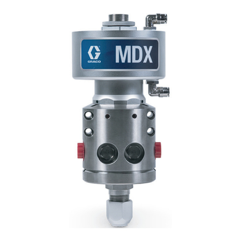
  9. Graco 239850 Operation manual

Graco 239850 Operation manual

This manual suits for next models

3

Other Graco Control Unit manuals

Graco 202844 Evenflo User manual

Graco

Graco 202844 Evenflo User manual

Graco 24J415 Parts list manual

Graco

Graco 24J415 Parts list manual

Graco EnDure User manual

Graco

Graco EnDure User manual

Graco CGM 25B127 Parts list manual

Graco

Graco CGM 25B127 Parts list manual

Graco E-Flo 24P821 Operation manual

Graco

Graco E-Flo 24P821 Operation manual

Graco PM5 238511 Datasheet

Graco

Graco PM5 238511 Datasheet

Graco PD44 Manual instruction

Graco

Graco PD44 Manual instruction

Graco Pulse 25D130 Manual

Graco

Graco Pulse 25D130 Manual

Graco 571169 User manual

Graco

Graco 571169 User manual

Graco SDP8 Series Owner's manual

Graco

Graco SDP8 Series Owner's manual

Graco Therm-O-Flow Series Operation manual

Graco

Graco Therm-O-Flow Series Operation manual

Graco 24R021 Parts list manual

Graco

Graco 24R021 Parts list manual

Graco B52100 Parts list manual

Graco

Graco B52100 Parts list manual

Graco CleanShot User manual

Graco

Graco CleanShot User manual

Graco 25D614 User manual

Graco

Graco 25D614 User manual

Graco Trabon MD Series User manual

Graco

Graco Trabon MD Series User manual

Graco LDP5 User manual

Graco

Graco LDP5 User manual

Graco USP User manual

Graco

Graco USP User manual

Graco EM5 Series Datasheet

Graco

Graco EM5 Series Datasheet

Graco Advanjet 26B970 Manual instruction

Graco

Graco Advanjet 26B970 Manual instruction

Graco 2001401 User manual

Graco

Graco 2001401 User manual

Graco Uniblock Series User manual

Graco

Graco Uniblock Series User manual

Graco CleanShot 244160 Parts list manual

Graco

Graco CleanShot 244160 Parts list manual

Graco 256653 User manual

Graco

Graco 256653 User manual

Popular Control Unit manuals by other brands

Seitz 14A80 user manual

Seitz

Seitz 14A80 user manual

Wilo RS485 Installation and operating instructions

Wilo

Wilo RS485 Installation and operating instructions

Becker CentralControl CC41 Commissioning Instruction

Becker

Becker CentralControl CC41 Commissioning Instruction

SICK CDB650 operating instructions

SICK

SICK CDB650 operating instructions

Panduit NetKey NKP5E88M Series installation instructions

Panduit

Panduit NetKey NKP5E88M Series installation instructions

MX Options Concentric Petite Fitting instructions

MX

MX Options Concentric Petite Fitting instructions

Clean Water Systems Fleck 2510 Installation & start?up guide

Clean Water Systems

Clean Water Systems Fleck 2510 Installation & start?up guide

Fairchild FSB44104A user guide

Fairchild

Fairchild FSB44104A user guide

LEGRAND Wattstopper LMIN-104 installation instructions

LEGRAND

LEGRAND Wattstopper LMIN-104 installation instructions

PMK ATT10BNCS instruction manual

PMK

PMK ATT10BNCS instruction manual

Tektronix TDS3FFT user manual

Tektronix

Tektronix TDS3FFT user manual

Woodward easYgen Technical manual

Woodward

Woodward easYgen Technical manual

Balluff BNI EIP-502-105-R015 user guide

Balluff

Balluff BNI EIP-502-105-R015 user guide

NXP Semiconductors TWR-LS1021A Getting started

NXP Semiconductors

NXP Semiconductors TWR-LS1021A Getting started

Advantech PCM-3117 Startup manual

Advantech

Advantech PCM-3117 Startup manual

Danfoss MCO 101 manual

Danfoss

Danfoss MCO 101 manual

Moons' Lin Engineering R701P user manual

Moons'

Moons' Lin Engineering R701P user manual

Aventics RV1 operating instructions

Aventics

Aventics RV1 operating instructions

manuals.online logo
manuals.online logoBrands
  • About & Mission
  • Contact us
  • Privacy Policy
  • Terms and Conditions

Copyright 2025 Manuals.Online. All Rights Reserved.

Instructions – Parts List
GRACO INC.ąP.O. BOX 1441ąMINNEAPOLIS, MNą55440-1441
Copyright 1997, Graco Inc. is registered to I.S. EN ISO 9001
Viscon HP Heater Modules
For 3:1 PresidentRPump Modules
300 psi (2.1 MPa, 21 bar) Maximum Working Pressure
Part No. 239850, Series B
With 120V Viscon HP Heater
Part No. 239851 and 239852 Series B
With 240V Viscon HP Heater
Part No. 241883, Series B
With 200V Viscon HP Heater
308771 rev.E
Read warnings and instructions.
See page 2 for table of contents.
Pump Module and Fluid Filter
are not included
7849A
Parts
2 308771
Table of Contents
Warnings 2. . . . . . . . . . . . . . . . . . . . . . . . . . . . . . . . . . . . . .
Installation 4. . . . . . . . . . . . . . . . . . . . . . . . . . . . . . . . . . . . .
Operation 7. . . . . . . . . . . . . . . . . . . . . . . . . . . . . . . . . . . . .
Parts 10. . . . . . . . . . . . . . . . . . . . . . . . . . . . . . . . . . . . . . . .
Technical Data 11. . . . . . . . . . . . . . . . . . . . . . . . . . . . . . . .
Mounting Hole Layout 11. . . . . . . . . . . . . . . . . . . . . . . . . .
Graco Standard Warranty 12. . . . . . . . . . . . . . . . . . . . . .
Graco Information 12. . . . . . . . . . . . . . . . . . . . . . . . . . . . .
Symbols
Warning Symbol
WARNING
This symbol alerts you to the possibility of serious
injury or death if you do not follow the instructions.
Caution Symbol
CAUTION
This symbol alerts you to the possibility of damage to
or destruction of equipment if you do not follow the
instructions.
WARNING
INSTRUCTIONS
EQUIPMENT MISUSE HAZARD
Equipment misuse can cause the equipment to rupture or malfunction and result in serious injury.
DThis equipment is for professional use only.
DRead all instruction manuals, tags, and labels before operating the equipment.
DUse the equipment only for its intended purpose. If you are uncertain about usage, call your Graco
distributor.
DDo not alter or modify this equipment. Use only genuine Graco parts and accessories.
DCheck equipment daily. Repair or replace worn or damaged parts immediately.
DDo not exceed the maximum working pressure stated on the equipment or in the Technical Data
for your equipment. Do not exceed the maximum working pressure of the lowest rated component
in your system.
DUse fluids and solvents which are compatible with the equipment wetted parts. Refer to the Tech-
nical Data section of all equipment manuals. Read the fluid and solvent manufacturer’s warnings.
DRoute hoses away from traffic areas, sharp edges, moving parts, and hot surfaces. Do not expose
Graco hoses to temperatures above 180_F (82_C) or below –40_F (–40_C).
DDo not touch the heater during operation; it is very hot.
DWear hearing protection when operating this equipment.
DDo not lift pressurized equipment.
DComply with all applicable local, state, and national fire, electrical, and safety regulations.
MOVING PARTS HAZARD
Moving parts, such as the air motor piston, can pinch or amputate your fingers.
DKeep clear of all moving parts when starting or operating the pump.
DBefore servicing the equipment, follow the Pressure Relief Procedure on page 7 to prevent the
equipment from starting unexpectedly.
308771 3
WARNING
PRESSURIZED EQUIPMENT HAZARD
Spray from the gun, hose leaks, or ruptured components can splash fluid in the eyes or on the skin
and cause serious injury.
DDo not point the gun at anyone or at any part of the body.
DDo not stop or deflect leaks with your hand, body, glove or rag.
DFollow the Pressure Relief Procedure on page 7 whenever you: are instructed to relieve pres-
sure; stop spraying; clean, check, or service the equipment; and install or clean the spray tip.
DTighten all fluid connections before operating the equipment.
DCheck the hoses, tubes, and couplings daily. Replace worn, damaged, or loose parts immediately.
Permanently coupled hoses cannot be repaired; replace the entire hose.
FIRE, EXPLOSION, AND ELECTRIC SHOCK HAZARD
Improper grounding, poor ventilation, open flames or sparks can cause a hazardous condition and
result in a fire or explosion and serious injury.
DThe electric heater must be installed, operated, and serviced only by trained, qualified personnel
who fully understand the requirements stated in the heater instruction manual (supplied).
DGround the equipment and the object being sprayed. Refer to Grounding on page 6.
DIf there is any static sparking or you feel an electric shock while using this equipment, stop spray-
ing immediately. Do not use the equipment until you identify and correct the problem.
DProvide fresh air ventilation to avoid the buildup of flammable fumes from solvents or the fluid
being sprayed.
DKeep the spray area free of debris, including solvent, rags, and gasoline.
DElectrically disconnect all equipment in the spray area.
DExtinguish all open flames or pilot lights in the spray area.
DDo not smoke in the spray area.
DDo not turn on or off any light switch in the spray area while operating or if fumes are present.
DDo not operate a gasoline engine in the spray area.
TOXIC FLUID HAZARD
Hazardous fluid or toxic fumes can cause serious injury or death if splashed in the eyes or on the skin,
inhaled, or swallowed.
DKnow the specific hazards of the fluid you are using.
DStore hazardous fluid in an approved container. Dispose of hazardous fluid according to all local,
state and national guidelines.
DAlways wear protective eyewear, gloves, clothing and respirator as recommended by the fluid and
solvent manufacturer.
4 308771
Installation
General Information
NOTE: Reference numbers and letters in parentheses
in the text refer to the callouts in the figures and the
parts drawing.
Prepare the Operator
All persons who operate the equipment must be
trained in the safe, efficient operation of all system
components as well as the proper handling of all fluids.
All operators must thoroughly read all instruction
manuals, tags, and labels before operating the equip-
ment.
Prepare the Site
Ensure that the wall is strong enough to support the
weight of the heater and accessories, fluid, hoses, and
stress caused during operation.
Keep the site clear of any obstacles or debris that
could interfere with the operator’s movement.
Installing the Heater Module
WARNING
FIRE, EXPLOSION, AND ELECTRIC
SHOCK HAZARD
The Viscon HP Heater must be installed
by a qualified electrician in compliance
with all state and local codes and regula-
tions, to reduce the risk of electric shock
or other serious injury during installation
or operation.
When installing in a flammable atmo-
sphere (hazardous location) refer to
Article 500 of the US National Electric Code or
other applicable agency standards to plan the
work.
Refer to the Technical Data and to the supplied
Viscon HP Heater manual for information on heater
power supply requirements.
Do not plug in or unplug a power cord in any area
containing flammable fluids or fumes, to avoid fire
or explosion resulting in serious injury.
Do not put all flammable materials and debris on
or near the heater. Keep the work area clean.
WARNING
COMPONENT RUPTURE HAZARD
Heat causes fluid to expand. If the
heated fluid is trapped with nowhere to
expand, it can cause component rupture.
Be sure to keep the heated fluid circulating (turn
the 3-way recirculation valve to the circulation
position). Do not install a fluid shutoff device
between the heater and the gun.
To convert a pump module to a heated package, install
the heater module as follows.
NOTE: Refer to Fig. 1, and to the Mounting Hole
Layout on page 11.
WARNING
To reduce the risk of serious injury whenever you
are instructed to relieve pressure, always follow the
Pressure Relief Procedure on page 7.
1. Relieve the pressure.
2. Unscrew the swivel (A) from the nipple (B). Re-
move the fluid filter (C) and connected parts.
Remove the nipple (B) and ball valve (F) from the
filter and discard them. See the Disassembly
Detail in Fig. 1.
3. Position the heater bracket (5) to the right of the
pump bracket (D), at the same height. The two
slots must face up. The center of the two outer left
holes must be no more than 9 in. (228 mm) from
the right edge of the pump bracket. See page 11.
4. Check that the heater bracket (5) is level. Using
the bracket as a template, mark the four outer
holes on the wall. Refer to the Mounting Hole
Layout on page 11. The four outer holes are used
to mount the bracket to the wall, and the two inner
slots and two inner holes are to mount the heater
(1) to the bracket.
5. Drill four holes in the wall.
6. Bolt the bracket (5) to the wall with 1/2 in. bolts
and washers. Use bolts that are long enough to
keep the bracket from vibrating during operation.
7. Install two screws (E, included with the heater) into
the top two heater mounting posts until they are
about 1/8 in. (3 mm) from fully installed.
308771 5
Installation
8. Using two people, lift the heater (1) onto the brack-
et (5) so the two screw heads (E) slide into the
slots. Have one person hold the heater in place
while the other installs the remaining two screws
(supplied with the heater) through the bracket and
into the bottom mounting posts. Tighten all four
screws.
9. Connect the free end of the heater supply hose (2)
to the swivel (A) at the pump fluid outlet. Tighten
securely.
10. Screw the fluid filter (C) assembly onto the bushing
(4) at the heater outlet.
7782C
7781B
Fig. 1
1Remove and discard.
Disassembly
Detail
A
B
C
D
E
5
A
21
C
3
4
1
2
3
2
3
4Connect a 1 to 3 ft (0.3 to 0.9 m) hose here.
4
F1
Refer to text and Mounting Hole Layout on page 11 for
correct positioning.
Install top two screws until they are about 1/8 in. (3 mm)
from fully installed.
6
7
6 308771
Installation
Connect the Fluid Lines
Connect a 1 to 3 ft (0.3 to 0.9 m) hose to the tee at the
outlet of the fluid filter, to isolate the pump module from
the main fluid line. Connect the other end of the hose
to the main fluid line.
Grounding
WARNING
FIRE, EXPLOSION, AND
ELECTRIC SHOCK HAZARD
Before operating the pump, ground the
system as explained below. Also read
the section FIRE, EXPLOSION, AND
ELECTRIC SHOCK HAZARD on page
3.
1. Pump: use a ground wire and clamp. See Fig. 2.
Loosen the grounding lug locknut (W) and washer
(X). Insert one end of the ground wire (Y) into the
slot in lug (Z) and tighten the locknut securely.
Connect the ground clamp to a true earth ground.
Fig. 2
W
Y
X
Z
0720
2. Viscon HP Heater: refer to the heater manual,
supplied.
3. Air and fluid hoses: use only electrically conductive
hoses.
4. Air compressor: follow manufacturer’s recommen-
dations.
5. Spray gun: ground through connection to a prop-
erly grounded fluid hose and pump.
6. Agitator: use a ground wire and clamp (Y). See
Fig. 3. Loosen the grounding lug locknut (W) and
washer (X). Insert one end of the ground wire (Y)
into the slot in lug (Z) and tighten the locknut
securely. Connect the ground clamp to a true earth
ground.
Fig. 3
W
Y
X
Z
0720
H
7. Suction hose: attach the hose (H) ground wire to
the ground lug on the agitator. See Fig. 3. If you
are not using an agitator, attach the wire to the
fluid supply container.
8. Fluid supply container: follow your local code.
9. Object being sprayed: follow your local code.
10. Solvent pails used when flushing: follow your local
code. Use only metal pails, which are conductive,
placed on a grounded surface. Do not place the
pail on a nonconductive surface, such as paper or
cardboard, which interrupts the grounding continu-
ity.
11. To maintain grounding continuity when flushing or
relieving pressure, hold a metal part of the spray
gun firmly to the side of a grounded metal pail,
then trigger the gun.
308771 7
Operation
Pressure Relief Procedure
WARNING
PRESSURIZED EQUIPMENT HAZARD
The system pressure must be manually relieved to
prevent the system from starting or spraying acci-
dentally. To reduce the risk of an injury from acci-
dental spray from the gun, splashing fluid, or
moving parts, follow the Pressure Relief Proce-
dure whenever you:
Dare instructed to relieve the pressure,
Dstop spraying,
Dcheck or service any of the system equipment,
Dor install or clean the spray nozzle.
WARNING
HOT SURFACE HAZARD
Do not touch the heater while it is oper-
ating. Allow the heater to cool for at least
10 minutes before flushing or servicing
it.
WARNING
FIRE AND EXPLOSION HAZARD
Do not plug in or unplug a power cord in
any area containing flammable fluids or
fumes, to avoid fire or explosion result-
ing in serious injury.
1. Disconnect the electric power to the heater (1).
2. Circulate the fluid for at least 10 minutes to cool
the heated fluid and the heater.
3. Close the red-handled bleed-type master air valve
(G, required in your system). See Fig. 4.
4. Place the drain hose (H) into a waste container.
Turn the 3-way recirculation valve (J) to the drain
position.
5. Trigger the gun at the last gun station to relieve
fluid pressure. Maintain firm metal-to-metal contact
between the gun and a grounded waste pail.
Repeat for all gun stations.
6. Open the drain valve (K) to relieve fluid pressure
which may be trapped in the pump or hose.
If you suspect that pressure is not fully relieved after
following the steps above, wrap a fitting near the pump
outlet with a rag, and slowly and carefully loosen the
fitting to relieve pressure. Be careful to protect your
eyes from splashing.
Preventive Maintenance Schedule
The operating conditions of your particular system
determine how often maintenance is required. Estab-
lish a preventive maintenance schedule by recording
when and what kind of maintenance is needed, and
then determine a regular schedule for checking your
system.
8 308771
Operation
Heater Operation
Before operating the heater, read the heater instruction
manual 309524 which is supplied.
Prime the Pump
1. Disconnect the electric power to the heater before
priming the pump.
2. Open the fluid shutoff valve (L).
3. Open the back pressure regulator (M). Turn the
3-way recirculation valve (J) to the circulation
position.
4. Open the spray gun at the last gun station and
keep it open while starting the pump.
5. Open the bleed-type master air valves (G, N).
6. Slowly open the air filter/regulator (P) until the
pump starts. The air filter/regulator controls the
pump speed and fluid outlet pressure.
7. When fluid comes from the gun, release the gun
trigger. The pump will continue to cycle as long as
air is supplied and the back pressure regulator (M)
is open.
8. One at a time, open any other guns in the system
to purge air from the lines.
NOTE: In a circulating system, the pump will continue
to cycle as long as air is supplied and the back pres-
sure regulator is open. In a direct supply system, the
pump starts when the gun is opened, and stops when
the gun is closed.
WARNING
COMPONENT RUPTURE HAZARD
To reduce the risk of overpressurizing
your system, which could cause
component rupture and serious injury,
never exceed the specified maximum air input
pressure to the package (see Technical Data on
page 11).
CAUTION
Do not allow the pump to run dry. It will quickly
accelerate to a high speed, causing damage. If your
pump is running too fast, stop it immediately and
check the fluid supply. If the container is empty and
air has been pumped into the lines, refill the con-
tainer and prime the pump and the lines, or flush and
leave it filled with a compatible solvent. Eliminate all
air from the fluid system.
Adjust the Spray Pattern
1. Start the pump. Connect the electric power to the
heater. Turn the 3-way recirculation valve (J) to
the circulation position.
2. Set the heater control to a trial point (4 or 5).
3. Circulate fluid through the pump for at least 10
minutes, at very low pressure. Check the tempera-
ture on the heater thermometer.
4. Adjust the fluid pressure and temperature to the
lowest settings necessary to get the desired re-
sults. Use the air filter/regulator (P) and the back
pressure regulator (M) to adjust the pump speed
and fluid pressure until the spray is completely
atomized. Refer to the back pressure valve and
heater manuals (supplied) for adjustment proce-
dures. Higher pressures and temperatures may
not improve the spray pattern and will cause
premature component wear.
5. To adjust the spray pattern, follow the complete
instructions in your gun manual.
WARNING
COMPONENT RUPTURE HAZARD
To reduce the risk of overpressurizing
your package, which could cause com-
ponent rupture and serious injury, never
exceed 100 psi (0.7 MPa, 7 bar) air input pressure
to the package. Also refer to the Technical Data
on page 11 and to your separate component manu-
als.
Heat causes fluid to expand. If the heated fluid is
trapped with nowhere to expand, it can cause
component rupture. Be sure to keep the heated
fluid circulating by turning the 3-way recirculation
valve (J) to the circulation position. Do not install a
fluid shutoff device between the heater and the
gun.
308771 9
Operation
7760B
Fig. 4
N
Detail of Air Controls
C
L
M
J
G
K
PY
2
1
A
H
See Detail of Air Controls in upper left corner.
1
2
Mount so the top of the bracket is 4 to 5 ft
(1.2 to 1.5 m) above the floor.
3
The center of the two outer left holes of the heater
bracket must be no more than 9 in. (228 mm) from the
right edge of the pump bracket. See page 11.
1 2
3
10 308771
Parts
1Pump Module. Not included.
1
Supply Module. Not included.
2
1
2
3
4
5
2
1
Part
of
Ref.
No.
Not used with Pump Module 232078.
3
3
7782C
6
7
Ref.
No. Description
Module
239850
Module
239851
Module
239852
Module
241883 Qty
1HEATER, fluid, 120V; see manual 309524 245848 1
HEATER, fluid, 240V; see manual 309524 245863 245863 1
HEATER, fluid, 200V, see manual 309524 245862 1
2HOSE, supply, heater; nylon; 1/2 in. (13 mm) ID; 1/2 npt(mbe) sst cou-
plings;
2 ft (0.61 m)
114253 114253 114253 114253 1
3NIPPLE; 3/8 npt; sst 111873 111873 111873 111873 1
4BUSHING; 3/4 npt(m) x 3/8 npt(f); sst 500352 500352 500352 500352 1
5BRACKET, heater 192585 192585 192585 1
6BUSHING, reducer, pipe 502265 502265 502265 502265 1
7FITTING, coupler 117627 117627 117627 117627 1