Graco 24W159 User manual

Installation-Parts
Isolated Isolated
IsolatedPump Pump
PumpExpansion Expansion
ExpansionKits Kits
Kits334512C
EN
For For
Foruse use
usewith with
witha a
aProMix® ProMix®
ProMix®MC0500 MC0500
MC0500Proportioner Proportioner
Proportionerto to
topump pump
pumpcolor, color,
color,catalyst, catalyst,
catalyst,and and
andsolvent. solvent.
solvent.For For
Forprofessional professional
professionaluse use
use
only. only.
only.
Important Important
ImportantSafety Safety
SafetyInstructions Instructions
Instructions
ReadallwarningsandinstructionsinthismanualandinyourPD2K
Installation,Operation,andRepairmanuals.
Save Save
Savethese these
theseinstructions. instructions.
instructions.
Seepage3formodelpartnumbersand
approvalsinformation.
PROVENQUALITY.LEADINGTECHNOLOGY.

Contents Contents
Contents
RelatedManuals................................................2
Models...............................................................3
Warnings...........................................................4
ImportantIsocyanate(ISO)Information................7
IsocyanateConditions..................................7
MaterialSelf-ignition.....................................7
KeepComponentsAandBSeparate............7
MoistureSensitivityofIsocyanates................8
ChangingMaterials......................................8
Installation..........................................................9
BeforeInstallingtheKit.................................9
InstallthePump..........................................9
TSLCupKit.................................................11
FluidConnections........................................13
ElectricalConnections..................................14
Grounding...................................................16
CompletetheInstallation..............................17
Repair................................................................19
DoseValveTubingConnections...................19
ReplacePumpControlModule.....................21
ElectricalSchematics..........................................22
PumpExpansionKitParts...................................28
Notes................................................................31
Dimensions........................................................32
TechnicalData...................................................33
GracoStandardWarranty....................................34
Related Related
RelatedManuals Manuals
Manuals
Manual Manual
ManualNo. No.
No.Description Description
Description
3A2800PD2KProportionerRepair-Parts
Manual,ManualSystems
332457PD2KProportionerInstallation
Manual
332562PD2KProportionerOperation
Manual,ManualSystems
3A2801MixManifoldInstructions-Parts
Manual
Manual Manual
ManualNo. No.
No.Description Description
Description
332339PumpRepair-PartsManual
332454ColorChangeValveRepair-Parts
Manual
332455ColorChangeKitsInstructions-
PartsManual
332456PumpExpansionKits
Installation-PartsManual
2334512C

Models
Models Models
Models
Kit Kit
KitPart Part
PartNo. No.
No.Pump Pump
PumpUsed Used
UsedDescription Description
DescriptionMaximum Maximum
MaximumFluid Fluid
Fluid
Working Working
WorkingPressure Pressure
Pressure
24W15924W273♦35ccLowPressureColororCatalyst
PumpKit(Isolated)
300psi(2.068
MPa,20.68bar)
24W16024W274♦70ccLowPressureColorPump
Kit(Isolated)
300psi(2.068
MPa,20.68bar)
24W27724W303♦35ccHighPressureColororCatalyst
PumpKit(Isolated)
1500psi(10.34
MPa,103.4bar)
24W27824W304♦70ccHighPressureColorPump
Kit(Isolated)
1500psi(10.34
MPa,103.4bar)
♦Theuidsectionofthesepumpsisapprovedforplacementinthehazardousarea.Themountingplateis
anapprovedpartitionbetweenthehazardousandnon-hazardousareas.
Figure1.PumpExpansionKitIdenticationLabel
334512C3

Warnings
Warnings Warnings
Warnings
Thefollowingwarningsareforthesetup,use,grounding,maintenance,andrepairofthisequipment.The
exclamationpointsymbolalertsyoutoageneralwarningandthehazardsymbolsrefertoprocedure-specic
risks.Whenthesesymbolsappearinthebodyofthismanualoronwarninglabels,referbacktothese
Warnings.Product-specichazardsymbolsandwarningsnotcoveredinthissectionmayappearthroughout
thebodyofthismanualwhereapplicable.
WARNING WARNING
WARNING
FIRE FIRE
FIREAND AND
ANDEXPLOSION EXPLOSION
EXPLOSIONHAZARD HAZARD
HAZARD
Flammablefumes,suchassolventandpaintfumes,inwork work
workarea area
areacanigniteorexplode.Tohelp
preventreandexplosion:
•Useequipmentonlyinwellventilatedarea.
•Eliminateallignitionsources;suchaspilotlights,cigarettes,portableelectriclamps,and
plasticdropcloths(potentialstaticarc).
•Keepworkareafreeofdebris,includingsolvent,ragsandgasoline.
•Donotplugorunplugpowercords,orturnpowerorlightswitchesonoroffwhenammable
fumesarepresent.
•Groundallequipmentintheworkarea.SeeGrounding Grounding
Groundinginstructions.
•Useonlygroundedhoses.
•Holdgunrmlytosideofgroundedpailwhentriggeringintopail.Donotusepaillinersunless
theyareantistaticorconductive.
•Stop Stop
Stopoperation operation
operationimmediately immediately
immediatelyifstaticsparkingoccursoryoufeelashock,Donotuse
equipmentuntilyouidentifyandcorrecttheproblem.
•Keepaworkingreextinguisherintheworkarea.
ELECTRIC ELECTRIC
ELECTRICSHOCK SHOCK
SHOCKHAZARD HAZARD
HAZARD
Thisequipmentmustbegrounded.Impropergrounding,setup,orusageofthesystemcan
causeelectricshock.
•Turnoffanddisconnectpoweratmainswitchbeforedisconnectinganycablesandbefore
servicingorinstallingequipment.
•Connectonlytogroundedpowersource.
•Allelectricalwiringmustbedonebyaqualiedelectricianandcomplywithalllocalcodes
andregulations.
4334512C

Warnings
WARNING WARNING
WARNING
SKIN SKIN
SKININJECTION INJECTION
INJECTIONHAZARD HAZARD
HAZARD
High-pressureuidfromgun,hoseleaks,orrupturedcomponentswillpierceskin.Thismay
looklikejustacut,butitisaseriousinjurythatcanresultinamputation.Get Get
Getimmediate immediate
immediatesurgical surgical
surgical
treatment. treatment.
treatment.
•Donotspraywithouttipguardandtriggerguardinstalled.
•Engagetriggerlockwhennotspraying.
•Donotpointgunatanyoneoratanypartofthebody.
•Donotputyourhandoverthespraytip.
•Donotstopordeectleakswithyourhand,body,glove,orrag.
•FollowthePressure Pressure
PressureRelief Relief
ReliefProcedure Procedure
Procedurewhenyoustopspraying/dispensingandbefore
cleaning,checking,orservicingequipment.
•Tightenalluidconnectionsbeforeoperatingtheequipment.
•Checkhosesandcouplingsdaily.Replacewornordamagedpartsimmediately.
MOVING MOVING
MOVINGPARTS PARTS
PARTSHAZARD HAZARD
HAZARD
Movingpartscanpinch,cutoramputatengersandotherbodyparts.
•Keepclearofmovingparts.
•Donotoperateequipmentwithprotectiveguardsorcoversremoved.
•Pressurizedequipmentcanstartwithoutwarning.Beforechecking,moving,orservicing
equipment,followthePressure Pressure
PressureRelief Relief
ReliefProcedure Procedure
Procedureanddisconnectallpowersources.
TOXIC TOXIC
TOXICFLUID FLUID
FLUIDOR OR
ORFUMES FUMES
FUMES
Toxicuidsorfumescancauseseriousinjuryordeathifsplashedintheeyesoronskin,
inhaled,orswallowed.
•ReadMSDSstoknowthespecichazardsoftheuidsyouareusing.
•Storehazardousuidinapprovedcontainers,anddisposeofitaccordingtoapplicable
guidelines.
•Alwayswearchemicallyimpermeablegloveswhenspraying,dispensing,orcleaning
equipment.
PERSONAL PERSONAL
PERSONALPROTECTIVE PROTECTIVE
PROTECTIVEEQUIPMENT EQUIPMENT
EQUIPMENT
Wearappropriateprotectiveequipmentwhenintheworkareatohelppreventseriousinjury,
includingeyeinjury,hearingloss,inhalationoftoxicfumes,andburns.Thisprotective
equipmentincludesbutisnotlimitedto:
•Protectiveeyewear,andhearingprotection.
•Respirators,protectiveclothing,andglovesasrecommendedbytheuidandsolvent
manufacturer.
334512C5

Warnings
WARNING WARNING
WARNING
EQUIPMENT EQUIPMENT
EQUIPMENTMISUSE MISUSE
MISUSEHAZARD HAZARD
HAZARD
Misusecancausedeathorseriousinjury.
•Donotoperatetheunitwhenfatiguedorundertheinuenceofdrugsoralcohol.
•Donotexceedthemaximumworkingpressureortemperatureratingofthelowestrated
systemcomponent.SeeTechnical Technical
TechnicalData Data
Datainallequipmentmanuals.
•Useuidsandsolventsthatarecompatiblewithequipmentwettedparts.SeeTechnical Technical
TechnicalData Data
Data
inallequipmentmanuals.Readuidandsolventmanufacturer’swarnings.Forcomplete
informationaboutyourmaterial,requestMSDSfromdistributororretailer.
•Donotleavetheworkareawhileequipmentisenergizedorunderpressure.
•TurnoffallequipmentandfollowthePressure Pressure
PressureRelief Relief
ReliefProcedure Procedure
Procedurewhenequipmentisnotinuse.
•Checkequipmentdaily.Repairorreplacewornordamagedpartsimmediatelywithgenuine
manufacturer’sreplacementpartsonly.
•Donotalterormodifyequipment.Alterationsormodicationsmayvoidagencyapprovals
andcreatesafetyhazards.
•Makesureallequipmentisratedandapprovedfortheenvironmentinwhichyouareusingit.
•Useequipmentonlyforitsintendedpurpose.Callyourdistributorforinformation.
•Routehosesandcablesawayfromtrafcareas,sharpedges,movingparts,andhotsurfaces.
•Donotkinkoroverbendhosesorusehosestopullequipment.
•Keepchildrenandanimalsawayfromworkarea.
•Complywithallapplicablesafetyregulations.
6334512C

ImportantIsocyanate(ISO)Information
Important Important
ImportantIsocyanate Isocyanate
Isocyanate(ISO) (ISO)
(ISO)Information Information
Information
Isocyanates(ISO)arecatalystsusedintwo
componentmaterials.
Isocyanate Isocyanate
IsocyanateConditions Conditions
Conditions
Sprayingordispensinguidsthatcontain
isocyanatescreatespotentiallyharmfulmists,
vapors,andatomizedparticulates
•Readandunderstandtheuidmanufacturer’s
warningsandSafetyDataSheet(SDS)toknow
specichazardsandprecautionsrelatedto
isocyanates.
•Useofisocyanatesinvolvespotentially
hazardousprocedures.Donotspraywiththe
equipmentunlessyouaretrained,qualied,
andhavereadandunderstoodtheinformation
inthismanualsandintheuidmanufacturer’s
applicationinstructionsandSDS.
•Useofincorrectlymaintainedormis-adjusted
equipmentmayresultinimproperlycured
material.Equipmentmustbecarefully
maintainedandadjustedaccordingto
instructionsinthemanual.
•Topreventinhalationofisocynatemists,vapors,
andatomizedparticulates,everyoneinthe
workareamustwearappropriaterespiratory
protection.Alwayswearaproperlytting
respirator,whichmayincludeasupplied-air
respirator.Ventilatetheworkareaaccordingto
instructionsintheuidmanufacturer’sSDS.
•Avoidallskincontactwithiscocyanates.
Everyoneintheworkareamustwearchemically
impermeablegloves,protectiveclothingand
footcoveringsasrecommendedbytheuid
manufacturerandlocalregulatoryauthority.
Followalluidmanufacturerrecommendations,
includingthoseregardinghandlingof
contaminatedclothing.Afterspraying,wash
handsandfacebeforeeatingordrinking.
Material Material
MaterialSelf Self
Self- -
-ignition ignition
ignition
Somematerialsmaybecomeself-ignitingifapplied
toothick.Readmaterialmanufacturer’swarnings
andmaterialMSDS.
Keep Keep
KeepComponents Components
ComponentsA A
Aand and
andB B
BSeparate Separate
Separate
Cross-contaminationcanresultincured
materialinuidlineswhichcouldcauseserious
injuryordamageequipment.Toprevent
cross-contamination:
•Never Never
NeverinterchangecomponentAandcomponent
Bwettedparts.
•Neverusesolventononesideifithasbeen
contaminatedfromtheotherside.
334512C7

ImportantIsocyanate(ISO)Information
Moisture Moisture
MoistureSensitivity Sensitivity
Sensitivityof of
ofIsocyanates Isocyanates
Isocyanates
Exposuretomoisture(suchashumidity)willcause
ISOtopartiallycure;formingsmall,hard,abrasive
crystals,whichbecomesuspendedintheuid.
EventuallyalmwillformonthesurfaceandtheISO
willbegintogel,increasinginviscosity.
NOTICE NOTICE
NOTICE
PartiallycuredISOwillreduceperformanceand
thelifeofallwettedparts.
•Alwaysuseasealedcontainerwithadesiccant
dryerinthevent,oranitrogenatmosphere.
Never Never
NeverstoreISOinanopencontainer.
•KeeptheISOpumpwetcuporreservoir(if
installed)lledwithappropriatelubricant.The
lubricantcreatesabarrierbetweentheISOand
theatmosphere.
•Useonlymoisture-proofhosescompatiblewith
ISO.
•Neverusereclaimedsolvents,whichmay
containmoisture.Alwayskeepsolvent
containersclosedwhennotinuse.
•Alwayslubricatethreadedpartswithan
appropriatelubricantwhenreassembling.
NOTE: NOTE:
NOTE:Theamountoflmformationandrateof
crystallizationvariesdependingontheblendofISO,
thehumidity,andthetemperature.
Changing Changing
ChangingMaterials Materials
Materials
NOTICE NOTICE
NOTICE
Changingthematerialtypesusedinyour
equipmentrequiresspecialattentiontoavoid
equipmentdamageanddowntime.
•Whenchangingmaterials,ushtheequipment
multipletimestoensureitisthoroughlyclean.
•Alwayscleantheuidinletstrainersafter
ushing.
•Checkwithyourmaterialmanufacturerfor
chemicalcompatibility.
•Whenchangingbetweenepoxiesandurethanes
orpolyureas,disassembleandcleanalluid
componentsandchangehoses.Epoxiesoften
haveaminesontheB(hardener)side.Polyureas
oftenhaveaminesontheA(resin)side.
8334512C

Installation
Installation Installation
Installation
Before Before
BeforeInstalling Installing
Installingthe the
theKit Kit
Kit
•Servicingtheelectricalcontrolboxexposesyou
tohighvoltage.Toavoidelectricshock,turnoff
poweratthemaincircuitbreakerbeforeopening
theenclosure.
•Allelectricalwiringmustbedonebyaqualied
electricianandcomplywithalllocalcodesand
regulations.
•Thisequipmentmustbegroundedtoreducethe
riskofstaticsparkingandelectricshock,which
couldcausefumestoigniteorexplode.See
Grounding,page16.
FollowthePressureReliefProcedurein
yourPD2Kmanualwheneveryousee
thissymbol.
Thisequipmentstayspressurizeduntilpressure
ismanuallyrelieved.Tohelppreventserious
injuryfrompressurizeduidsuchasskininjection,
splashinguid,andmovingparts,followthe
Pressure Pressure
PressureRelief Relief
ReliefProcedure Procedure
Procedureinyoursystemmanual
whenyoustopsprayingandbeforecleaning,
checking,orservicingtheequipment.
1.FlushthesystemasexplainedinyourPD2K
OperationManual.FollowthePressureRelief
ProcedureinyourPD2Kmanual.
2.Closethemainairshutoffvalveontheairsupply
line.
3.Removeelectricalpowerfromthesystem.
Install Install
Installthe the
thePump Pump
Pump
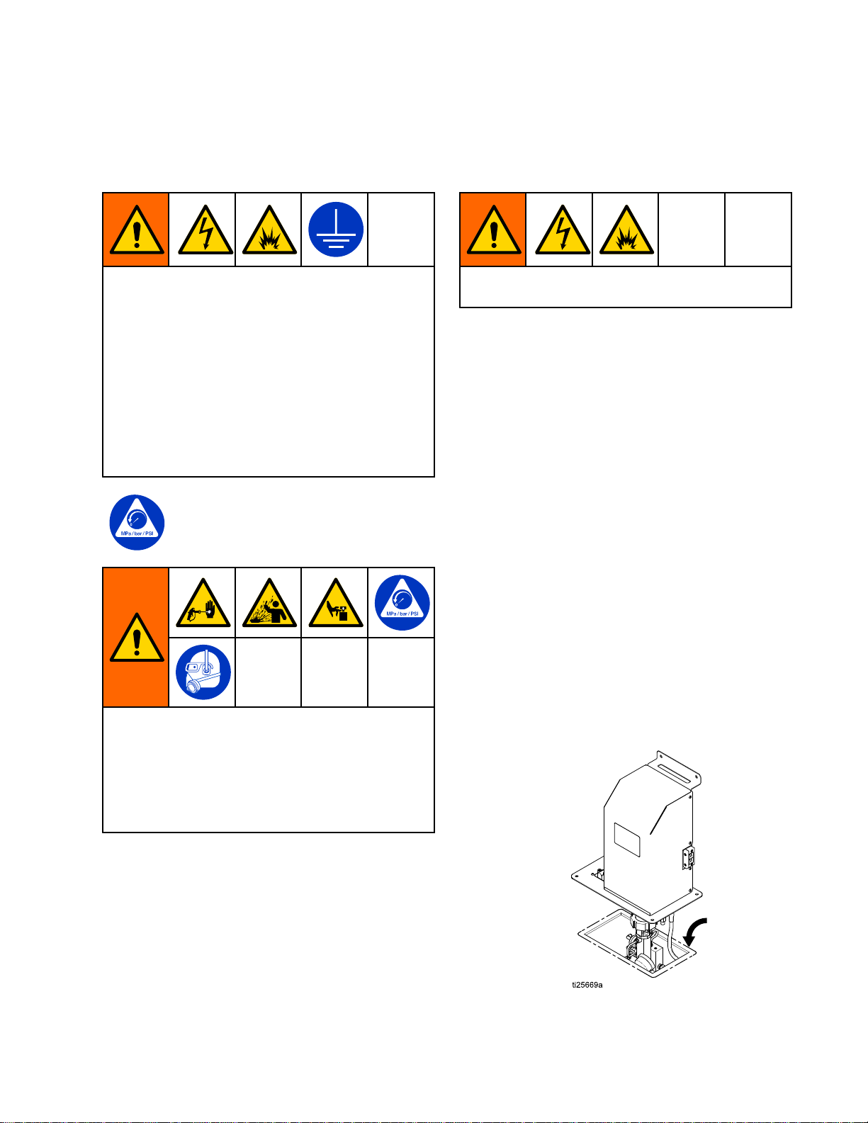
Theelectronicportionofthepumpkitmustremain
outsidethehazardouslocation.SeeFigure2.
1.FollowthestepsinBefore Before
BeforeInstalling Installing
Installingthe the
theKit, Kit,
Kit,inthe
previoussection.
2.Planyourinstallationsothatallpumpsare
locatedwithin6ft.ofthePD2Kelectricalcontrol
box(D).Eachmulti-conductorcable(10)must
beabletoreachfromthedualcablegrommet
(9)tooneoftheportsonthecontrolbox.See
ElectricalConnections,page14.SeealsoFigure
2.
NOTE: NOTE:
NOTE:Tomountpumpsonbothsidesofthe
controlbox,turnthepumpcontrolmodule(6)
over,andconnectthedualcablegrommet(9)on
theothersideoftherearmountingbracket.
3.Installthepumpassemblysecurelybybolting
therearmountingbracket(4)todesiredwallor
sturdysurface.SeeDimensions,page32.
4.Applyapprovedreproofsealanttothemating
surfaceofthemountingplate(1),toensure
anairtightseal.Mounttheplateonthe
horizontalsurfacethatisthebarrierbetween
thehazardousandnon-hazardousareas.See
Dimensions,page32.
334512C9

Installation
TSL TSL
TSLCup Cup
CupKit Kit
Kit
ThroatSealLiquid(TSL)lubricatesthepumpthroat
packingsanddosingvalves.TheTSLCupKit
suppliesTSLtotheupperandlowerthroatcartridges
ofthepump,andtothefourpumpdosingvalves.
NOTE: NOTE:
NOTE:TSLmustbeorderedseparately.OrderPart
No.206995,1quart(0.95liter).
1.Slidethekitmountingbracketontoanysideof
thepump’shexnut.
2.PlacetheTSLcup(51)intothebracket(51a).
Routingofthethroatsealtubing(51c)should
always always
alwaysslopeuptothereservoir.
NOTE: NOTE:
NOTE:Thepump’supperthroatcartridgehas
threeports(twoareplugged).Installthebarbed
tting(51b)intheportclosesttotheTSLcup,by
movingaplugifnecessary.
3.Checkthattheo-ringisinplaceonthebarbed
tting(51b).Applylowstrengththreadadhesive
andinstallthettingintheupperthroatcartridge
port.
4.Repeatforthelowerthroatcartridge.
5.Ifyouarelubricatingthedosingvalves,remove
theplugandgasketfromthevalveportclosest
totheTSLcup.Checkthattheo-ringisinplace
onthebarbedtting(51b).Applylowstrength
threadadhesiveandinstallthettinginthevalve
port.
NOTE: NOTE:
NOTE:Ifyouarenotlubricatingthedosing
valves,removetheunusedbarbedttings(51b)
fromthebottomoftheTSLcup(51).Applylow
strengththreadadhesiveandinstalltheplugs
andgasketssuppliedwiththekit.
6.Cutthetubing(51c)tolengthasrequired.
ConnecttheTSLcupttingstothettingsonthe
pumpandvalves.TSLisgravity-fedfromthe
cuptothepumpandvalves;positionthettings
andtubingtopreventkinksandenabletheTSL
toowfreely.
7.FillthecupwithTSL.
Figure3InstallTSLCupKit
334512C11

Installation
Air Air
AirConnections Connections
Connections
Connectthemainairsupplylinetotheairinletofthe
solenoidmanifold(40).
NOTE: NOTE:
NOTE:A6ft(1.83m)lengthof1/4in.(6mm)OD
polyethylenetubing(35)issuppliedwiththekitto
supplyairtotheexpansionpump’ssolenoidmanifold
(40).
1.Cuttheairsupplytubingthatleadsintothe
electricalcontrolbox(D).
2.InstalltheY-tting(55)suppliedinthekitto
restoreairsupplytotheelectricalcontrolbox(D).
3.Connectthesupplied1/4in.(6mm)ODtubing
(35)betweentheopenbranchoftheY-tting(55)
andtheairinletofthesolenoidmanifold(40).
Thislinesuppliesairtotheexpansionpump
solenoidmanifold,asshownintheillustration.
NOTE: NOTE:
NOTE:Ifyouareinstallingasecond,third,or
fourthpump,makeadditionalsplicesinthemain
airsupplylineandconnectinsamemanner.
Figure4SupplyingAirtotheExpansionPump
SolenoidManifold
12334512C

Installation
Electrical Electrical
ElectricalConnections Connections
Connections
NOTICE NOTICE
NOTICE
Toavoidelectricalcomponentdamage,removeall
systempowerbeforeplugginganyconnectors.
NOTE: NOTE:
NOTE:SeetheElectricalSchematics,page22.
1.Verifythatelectricalpowerisremovedfromthe
system.
2.Removethecoverfromtheelectricalcontrolbox.
3.Removetheknockout(K)fromthesideofthe
electricalcontrolbox.
4.Threadthecableintotheelectricalcontrolbox
andconnecttotheappropriateconnectionport
ontheenhanceduidcontrolmodule(Pump1
toP1,Pump2toP2,Pump3toP3,andPump
4toP4).
Figure6InstallGrommetinElectricalControl
Box
Figure7EnhancedFluidControlModule
ConnectionPoints
14334512C

Installation
5.Threadthe2–wirecable(52)upintothe
electricalboxthroughanexistinggrommetand
thewireway.Connectthecable(52)tothe
appropriateterminalsonthetopofthe48Vdc
powersupply(P1forpump1,P2forpump2,
P3forpump3,P4forpump4);redwireto+
terminal,blackwireto-terminal.
Figure848VdcPowerSupplyConnection
Points
6.Installthedualgrommet(9,shippedloose)on
thefreeendoftheD-SUBcable(10).
7.Fastenthegrommet(9)tothesideofthe
electricalcontrolbox,usingtwoscrews(11).
8.Reinstallthecoverontheelectricalcontrolbox.
334512C15

Installation
Grounding Grounding
Grounding
Thisequipmentmustbegroundedtoreducethe
riskofstaticsparkingandelectricshock.Electric
orstaticsparkingcancausefumestoigniteor
explode.Impropergroundingcancauseelectric
shock.Groundingprovidesanescapewireforthe
electriccurrent.
1.Verifythatthebaseunitisproperlygrounded.
SeethePD2Kinstallationmanualforcomplete
groundinginstructions.
2.Groundtheexpansionkitpump(s)asfollows:
a.Connectagroundwiretothegroundscrew
(8)ontheaddedpumpkit’sbackpanel(4).
Connecttheotherendofthegroundwireto
thesame same
sametrueearthgroundthatthemainunit
isconnectedto.Verifythattheaddedpump
isgroundedbytakingaresistancereading
fromthegroundscrew(8)ontheadded
pumpkit’sbackpanel(4)tothesystem’s
trueearthground.Resistancemustbeless
than1ohm.
Figure9GroundingthePumpExpansionKit
16334512C

Installation
Complete Complete
Completethe the
theInstallation Installation
Installation
1.Installthecover(29)ontheexpansionkit,using
thescrew(31).
Figure10InstallExpansionKitCover
2.Restoreelectricalpower.
3.Turnonthecontrolboxpowerswitch.
4.Press
andnavigatetoSystemScreen1
ontheAdvancedDisplayModule.Changethe
numberofColorPumpsandCatalystPumpsas
needed,basedonthekitinstallation.
Figure11SystemScreen1
334512C17

Installation
5.GotothePumpScreens.Themenubaratthe
topofthescreenwillnowshowseparatetabs
forallinstalledpumps.Eachpumphasthree
screens.Entertherequiredinformation,as
explainedinthePD2KOperationManual.
NOTE: NOTE:
NOTE:Ataminimum,youmustenterthe
PumpSizeonPumpScreen1andtransducer
calibrationdata“OutletOffsetFactor”and“Outlet
SensitivityFactor”onPumpScreen2(seeyour
PD2KOperationManual).Also,createarecipe
usingthenewmaterialnumber,whichcanbe
foundonPumpScreen1underAvailableColors
(orCatalysts).
Figure12Third(Color)PumpScreen
Figure13Fourth(Catalyst)PumpScreen
6.TheHomeScreenwillnowshowanimationsand
informationfortheaddedpumps.
Figure14PD2KHomeScreen(Advanced
DisplayModule)
7.SeethePD2KOperationManualtoreturnthe
systemtoservice.
18334512C

Repair
Repair Repair
Repair
Dose Dose
DoseValve Valve
ValveTubing Tubing
TubingConnections Connections
Connections
NOTE: NOTE:
NOTE:5/32in.(4mm)tubingconnectsthesolenoid
manifoldtothepump’sdosingvalves.SeethePump
TubingSchematiconthenextpage.Tubinglengths
mustbe18in.±1/2in.(457mm±13mm)forall
connections.Alwaysuseequallengthsoftubing,to
balancethetimingofthevalves.Lengthslongerthan
18in.(457mm)willincreasevalveresponsetime.
1.Onthebottomofthesolenoidmanifoldarefour
portswithtubettings:UPOPEN,UPCLOSED,
DOWNOPEN,andDOWNCLOSED.These
portsprovideairtoopenandclosethepump’s
inletdosingvalves.
Figure15TubingConnectionsatSolenoid
Manifold,toPumpInletManifold
a.Connectgreentubing(G)fromtheUPOPEN
ttingtothe90°tubettingonthesideofthe
INLETUPdosingvalve.
b.Connectredtubing(R)fromtheUPCLOSED
ttingtothe90°tubettingontheendofthe
INLETUPdosingvalve.
c.Connectblacktubing(K)fromtheDOWN
OPENttingtothe90°tubettingontheside
oftheINLETDOWNdosingvalve.
d.Connectredtubing(R)fromtheDOWN
CLOSEDttingtothe90°tubettingonthe
endoftheINLETDOWNdosingvalve.
Figure16InletManifoldTubingConnections
2.Onthesideofthesolenoidmanifoldarefour
portswith90°tubettings(notshown):UP
OPEN,UPCLOSED,DOWNOPEN,andDOWN
CLOSED.Theseportsprovideairtoopenand
closethepump’soutletdosingvalves.
Figure17TubingConnectionsatSolenoid
Manifold,toPumpOutletManifold
a.Connectbluetubing(B)fromtheUPOPEN
ttingtothe90°tubettingonthesideofthe
OUTLETUPdosingvalve.
b.Connectredtubing(R)fromtheUPCLOSED
ttingtothe90°tubettingontheendofthe
OUTLETUPdosingvalve.
Figure18OutletManifoldTubing
Connections
334512C19

Repair
c.Connectyellowtubing(Y)fromtheDOWN
OPENttingtothe90°tubettingontheside
oftheOUTLETDOWNdosingvalve.
d.Connectredtubing(R)fromtheDOWN
CLOSEDttingtothe90°tubettingonthe
endoftheOUTLETDOWNdosingvalve.
3.Repeatthesestepsforeachpumpinyour
system.
Seethefollowingtabletounderstandtherelationship
betweenpumpstrokeanddosevalveactuation.
Table Table
Table1 1
1Dose Dose
DoseValve Valve
ValveActuation Actuation
Actuation
Pump Pump
Pump
Stroke Stroke
Stroke
Up Up
UpInlet Inlet
Inlet
Valve Valve
Valve
Down Down
Down
Inlet Inlet
Inlet
Valve Valve
Valve
Up Up
Up
Outlet Outlet
Outlet
Valve Valve
Valve
Down Down
Down
Outlet Outlet
Outlet
Valve Valve
Valve
UpOpenClosedOpenClosed
DownClosedOpenClosedOpen
INLET UP
OUTLET UP
OPEN
CLOSED
Green (G)
Red (R)
Blue (B)
Red (R)
CLOSED
OPEN
UP EXH
INLET DOWN
OUTLET DOWN
OPEN
CLOSED
Black (K)
Red (R)
Yellow (Y)
Red (R)
CLOSED
OPEN
DOWN EXH
Figure19PumpTubingSchematic
20334512C
Other manuals for 24W159
1
This manual suits for next models
3
Table of contents
Other Graco Extender manuals