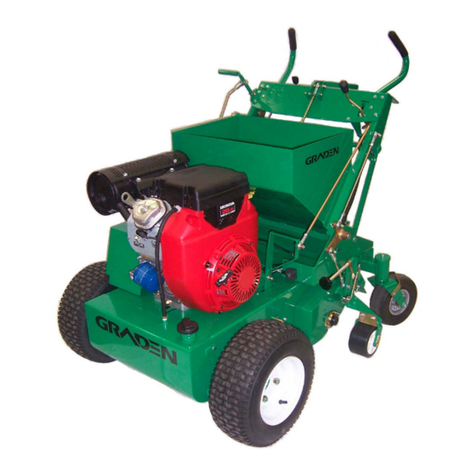
GRADEN SWING-WING SW04 User manual

G N
INDUSTRI ES PTV LTD
SW04
SWING-WING
VERTICUER/SCARIFIER
OWNERS MANUAL


Table of Contents
1. Specifications
1.1 Specifications
1.2 Statement of Machine Use
1.3 Serial Number Plate
2. To the Owner
2.1 Preliminary instructions
2.2 Warning symbols
2.3 Servicing the Swing-Wing Verticutter
3. Safety Information
3.1 General rules
3.2 Training
3.3 Personal Protective Equipment (PPE)
3.4 Preparation
3.5 Operational Safety
3.6 Maintenance Safety
4. Assembly Instructions
5. Operating Instructions
5.1 Preliminary checks
5.2 Set up
5.3 Transporting (traversing) the Verticutter
5.4 Verticutting
5.5 Shut down
6. Maintenance Operations
6.1 Adjustments and settings
6.1.1 Rotor belts (centre rotor)
6.1.2 Rotor belts (wing rotors)
6.2 Replacements
6.2.1 Blade replacement
6.2.1.1 Centre blade reel
6.2.1.2 Wing blade reels
6.2.2 Belt replacement
6.2.2.1 Rotor belts : centre reel
6.2.2.2 Rotor belts : wing reels
6.3 Gearbox
6.4 Maintenance schedule
7. Warranty
8. Parts & Illustrations
8.1 Parts Diagrams
8.2 Warning/Compliance Decals

1.1 Specifications
Model Graden SW04 Swing-Wing Verticutter
P.T.O. Horsepower 20 - 35 h.p.
Drive Belt drive via Tractor PTO
Gearbox Comer T27A Increasing Gearbox
Gearbox oil Gear Oil - SAE 80W90
Cutting Reels 1 Fixed (13 blades), 2 Floating (8 blades ea.)
Cutting width 1520mm (60 inches)
Cutting depth (nominal) 0 to 40mm (maximum with standard blades)
Blades
Standard :
Optional :
Tungsten carbide tipped spring steel
210mm x 2mm tip Part No. 0232
210mm x 3mm tip Part No. 0217
210mm x 1mm tip Part No. 1122
Blade tip speed
1250m/min (standard blades at normal PTO
speed of 540 rpm)
Weight 290 kg
Height 1110 mm (machine on stands)
Overall Width 1980 mm
Length 1330mm
Tyres 4.10/3.50 - 4 Slick Pattern (6 per machine)
Tyre pressure 275 - 345 kPa (40 -50 psi)
Rotor belts A47 Dayco Super 2 Series (8 per machine)

1.2 Statement of Machine Use
The Graden SW04 Swing-Wing Verticutter/Scarifier’s main use is as a
verticutting/scarifying/de-thatching tool on areas such as golf courses, bowling
greens, cricket wickets, tennis courts, and other sporting fields.
It is not for use on turf areas where rocks and other hard foreign bodies may be
present. The use of this machine in turf profiles of this nature will likely cause
premature wear or shattering of the blade tips and could result in rocks being
projected at dangerous speeds, resulting in potential injury to the operator or
damage to the machinery.
This machine is not for use in anything other than the soil profiles typically to be
found on the sporting fields mentioned above. Any use of this machine in any
other type of surface or for any other purpose may void the warranty.
Please contact Graden Industries if you are unsure about your application
complying with the intended use of this machine.
1.3 Serial Number Plate
The serial number plate layout is shown below. The serial number is comprised of
four sections. The first section is the model number, the second section is the mass
of the machine, the third section is the serial number and the fourth section is the
year of manufacture of the machine, as indicated below;

2. To the Owner
Read this manual before operating the Swing-Wing Verticutter
2.1 Preliminary Instructions
It is important that the owner completely familiarises themselves with the
contents of this manual
Keep this manual at hand as a ready reference for anybody using the Graden
Swing-Wing Verticutter
The designed and tested safety features of this machine are dependent on it
being operated within the limitations described in this manual
2.2 Warning Symbols
Throughout this manual the following symbols are used to indicate important safety
issues. When either or both of these symbols are present the operator must be
aware that there is the potential to damage equipment and/or incur serious
personal injury.
WARNING
This signal denotes a potential equipment hazard:
failing to follow the instructions or procedures may
result in equipment malfunction or damage.
DANGER
This signal denotes a serious personal safety hazard:
failing to follow the instructions or procedures may
result in serious, or even fatal, injury.

2.3 Servicing the SwingWing Verticutter
The Graden Swing-Wing Verticutter has been carefully engineered and
manufactured to provide safe, dependable and effective service.
As with all mechanical equipment it requires routine cleaning and maintenance.
Your authorised Graden representative has access to tools, genuine spares and
equipment to service any and all of your requirements.
Use only genuine Graden parts; substitute parts will void the warranty and may not
meet the safety and performance standards required for safe and effective
operation of the Swing-Wing Verticutter.
Please record the model and serial numbers of the Swing-Wing Verticutter in the
space provided below and quote this information when ordering parts or
communicating with Graden Industries or its’ approved representatives.
Model Number : __________________________
Serial Number : __________________________
Date Purchased : __________________________

3. Safety Information
This manual is provided to help you operate and maintain the Swing Wing
Verticutter. Please read it carefully.
It has been compiled from extensive field experience and engineering data.
In some aspects it is generalised because it is impossible to cover all operating
scenarios. However, combining the information provided in this manual with your
own increasing experience and knowledge with the Swing-Wing Verticutter will
enable you to develop procedures suitable for your individual needs.
The Swing-Wing Verticutter, like most modern machinery, is constantly undergoing
development on the basis of experience and market needs. At the time of printing,
material in this manual was current but may vary due to the aforementioned
ongoing development.
Graden Industries reserve the right to change the machinery specifications without
notice.
3.1 General Rules
Direction on the machine (right or left) is determined from standing behind the
machine and facing in the direction of forward travel, all directions are given in
this manual with this rule in mind
When viewed from the right side the blades rotate anti-clockwise (counter
rotating to the forward rotation of the tractor wheels)
This is a precision piece of machinery with high speed cutting blades
DANGER
Keep hands and feet away from rotating parts
of the Swing-Wing Verticutter, especially the
cutting blades
Do not allow children to operate the machine or be near it during its’ operation.
Never allow anyone to ride on the Swing-Wing Verticutter at any time.
Only people who are very familiar with the rules of safe operation should be
allowed to use this machine

Only use the machine during daylight or in good artificial light
Some illustrations in this manual show the Swing-Wing Verticutter with safety
guards removed. This is not a normal situation.
DANGER
Never operate the Swing-Wing Verticutter
with any of the covers or safety guards
removed or not properly secured.
3.2 Training
WARNING
Read this manual completely before
beginning to learn how to use the
Swing-Wing Verticutter
Do not allow anybody to operate the machine without instruction
Know your controls and how to stop the machine and shut down the tractor
quickly in an emergency
To maintain control and reduce the possibility of upset, damage or collision,
operate the machine smoothly. Avoid erratic operation and excessive speed.
The tractor has its’ own set of safety and operating rules. These must be
complied with.
DANGER
Read any manuals supplied with the tractor and know
how to stop it and shut down all actions in an emergency.

If the tractor is fitted with a Roll Over Protection Structure (ROPS), do not exceed
the ROPS weight certification and always wear your seat belt.
Be aware of the hazards associated with the tractor engine:
The fuel used (Petrol, diesel, etc.) is highly flammable so only use an
appropriate container
Never remove the fuel cap or add fuel while the engine is running or still
hot
Never add fuel indoors and wipe up any spillages
Never run the engine in an enclosed area because exhaust gases are
toxic
DANGER
The engine uses highly flammable petroleum
fuel and produces toxic exhaust gases.
Only add fuel to, or run, the engine in the
open - never indoors.
3.3 Personal Protective Equipment (PPE)
Clothing should be reasonably snug fitting and not free flowing so as to avoid
the risk of entanglement in moving parts.
Wear sturdy footwear, preferably steel capped safety shoes or boots
Use appropriate PPE for eyes, ears and hands
DANGER
Never wear sandals, sneakers or have
bare feet when operating the tractor.
3.4 Preparation
Ensure all safety warnings and decals are in place and legible (on both the
Swing-Wing and the tractor).
Ensure that the Swing-Wing Verticutter is correctly mounted on the tractor and
that the machine is properly adjusted.

Remove any accumulated debris that might represent a fire hazard.
Ensure that the blades are in a serviceable condition and that the rotor shaft
mounting bolts are secure.
Perform any appropriate scheduled maintenance before operating the
machine.
3.5 Operational Safety
Always disengage the P.T.O before attempting to start the tractor.
Always raise the Swing-Wing Verticutter clear of the turf before attempting to
engage the P.T.O.
Always raise the Swing-Wing Verticutter clear of the ground and disengage the
P.T.O when crossing gravel, walkways, roads, etc., or indeed any ground which
you do not wish to verticut.
Be very careful and maintain minimum ground speed when operating over
rough ground, around trees, ditches, fences or on sloping ground.
WARNING
Stay alert for holes, ditches or obstacles that
might obstruct the unit or cause it to tip over.
Never allow anybody in front or behind the tractor and Swing-Wing Verticutter
while operating. Before reversing, disengage the P.T.O. then lift the machine
clear of the ground and ensure that the area behind you is clear.
DANGER
Always raise the Swing-Wing, disengage the
P.T.O., stop the tractor engine and remove the
key in any of the following situations:
leaving the machine unattended
attempting to unclog or clear the blades
making any repairs or adjustments
inspecting the unit for damage after striking
any foreign object
Always repair any damage before recommencing operation.

3.6 Maintenance Safety
Maintenance on the Swing-Wing Verticutter is best carried out with the machine
mounted on the castor wheel-equipped supports that are supplied with the unit.
Alternatively, maintenance can be carried out with the unit mounted on the
tractor, so long as it is securely blocked up on jack stands. Do not rely on the
tractor hydraulics to maintain the unit at a safe working height.
DANGER
Raise the Swing-Wing clear of turf or surface,
disengage the P.T.O., turn off the engine, set the
park brake and remove the key before carrying
out any maintenance or servicing.
Never allow anybody near the tractor controls while adjustments, maintenance
or servicing are being performed.
Keep both the Swing-Wing and the tractor (especially around the engine) free
of any debris
Remove debris from underneath the Swing-Wing Verticutter after each use.
Verify that all warning labels and decals are present, visible and legible.
Periodically check that all bolts, fasteners and catches are secure and in safe
operating condition.
After any maintenance or servicing, ensure that all guards and safety devices
are correctly installed and secure before operating the Swing-Wing Verticutter.
DANGER
Frequently check the rotor blades. Verify that all
the tips are in good condition.
Ensure that the blades are firmly held and there
is no slack due to damaged or worn spacers.

4. Assembly Instructions
Your Verticutter has been manufactured, assembled and tested at Graden
Industries before being shipped.
Depending on your local distributor, your Verticutter may have been partially
disassembled prior to dispatch. Your machine may be received in the following
condition :
Left and Right wheel axle assemblies bolted in reverse mounting position (for
packing purposes only)
Castor wheels removed from supports
Left and Right Hand Uprights removed
Crossbar removed
P.T.O shaft (supplied separate)
As appropriate, please carry out the following assembly instructions.
Tools required : ½ inch AF spanner (x2)
9/16 inch AF spanner (x2)
¾ inch AF spanner (x2)
15/16 inch AF spanner (x2)
Large Adjustable spanner
Steps
1. Remove all packaging material.
2. Ensure that all documents are present. With each machine should be this
manual, and a manual for the PTO Shaft (this may still be attached to the PTO
Shaft).
3. Unscrew the stands from the pallet and remove the machine from the pallet.
4. Attach the Castor Wheels (5299) to the front (0622) and rear (0624) stands with
the bolts supplied (use ½ inch AF spanners).
5. Attach Height Connecting Rod (1119) to Rear Wheel Axle (1114), (use 15/16 inch
AF spanners), ensuring the Retaining Chain (1151) is hanging beneath the
Height Connecting Rod (1119).
6. Attach the Left and Right Hand Wheel Axle Assemblies (1115 & 1116) to their
respective Rotor Housings (1111 & 1112) with the bolts supplied as shown in
Diagram Three (use 9/16 inch AF spanners).
7. Attach the Left and Right Hand Uprights to the Swing-Wing Frame (use ¾ inch
AF spanners and large adjustable spanner) with the bolts supplied, but do not
tighten them up completely.
8. Fit the Crossbar (1118) to the Uprights (1096 & 1097), getting all four bolt and nut
sets started in the holes, (use 9/16 inch AF spanners), but before final tightening
of these bolts, tighten up all the bolts for the Uprights (1096/1097) to the Swing-
Wing Frame (1110). Now tighten the Crossbar (1118) bolts completely.
Your machine should now be assembled and ready to use.

5. Operating Instructions
DANGER
Do not operate the Verticutter until you
have completely read this manual.
5.1 Preliminary Checks
1. Clear any debris from above and underneath the machine
2. Ensure scheduled maintenance activities have been completed.
3. Inspect belts for condition and correct tension.
4. Inspect blades for wear or damage.
5. Ensure all guards and covers are firmly fixed in place
5.2 Set Up
1. Ensure that the Swing-Wing is on a firm, level surface
2. Release the four height adjustment locking levers (0970 & 1129) and
screw the four height adjustment screws (0986 & 1150) clockwise to lower
the wheels as far as they will go.
3. Lock the supports (0622 & 0624) in the raised position so that the Swing-
Wing is resting on its’ wheel assemblies.
4. Gradually raise the front (1113) and rear (1114) wheel axles so that the
centre, fixed blade reel is just about to touch the ground.
5. Gradually raise the left and right hand wheel axles (1115 & 1116) until
both of the Swing-Wing blade reels are about to touch the ground.
6. Attach the P.T.O shaft to the Swing-Wing, ensuring the locking pin pops
up.
7. Position the tractor in front of the Swing-Wing and lower the tractor 3-point
hitch.
8. Attach the lower tractor arms to the lifting pins, secure with 3/8” lynch
pins and connect the upper tractor arm to the hole, not the slot, in the
crossbar.
9. Adjust the tractor sway bars so that there is no side-to-side motion.
10.Attach the P.T.O. shaft to the tractor, ensuring the locking pin pops up.
11.Secure the P.T.O guard retaining chains at both ends.
12.Raise the Swing-Wing off the ground and verify that the unit is level.
13.This procedure establishes that the Verticutter is level. However this does
not ensure that the tractor and its’ hitch are even and level. Adjustments
may need to be made at the work site to compensate for any variations.
This is covered in 5.4
DANGER
The P.T.O retaining chains must be connected
to prevent the outer guard from rotating with
the P.T.O shaft

5.3 Transporting (Traversing) the SwingWing Verticutter
1. Raise the Swing-Wing just clear of the turf (ground).
2. Disengage the P.T.O
3. Drive smoothly to your next destination. Avoid excess speed, especially
over rough or uneven ground.
5.4 Verticutting
1. Once in position to use the machine, move the upper tractor arm hitch point
from the hole to the long slot. Adjust the tractor arm so that it is sitting in the
middle of the slot to allow the machine to tilt forward and back with the
undulations of the turf.
2. Set the depth of cut via the 4 height adjustment screws (0986 & 1150) to the
desired depth. Normal range of cut (with standard 210mm blades) is 0mm
to 40mm deep. Clockwise rotation of the screws produces a shallower cut ;
anti-clockwise produces a deeper cut. There is an indicator arm on the
back of the wheel axles which can help you in setting the heights level.
3. Start the tractor, raise the Verticutter clear of the turf and with the engine at
idle gently engage the P.T.O
4. Increase the P.T.O speed to 540 rpm.
5. Gently lower the Swing-Wing into the ground and allow the rotating blades
to pull themselves into the turf.
6. Make a test cut on level ground of several metres and check that the
Verticutter is cutting to a consistent depth across the full width of the cut.
7. Adjust the fore and aft tilt of the machine and the level on the wings if
required.
8. Following these level adjustments, adjust the depth of the cut by altering all
the height adjustment knobs by the same amount in the same direction if
required.
9. Repeat the short test cut and verify that the cut is even across the Verticutter
and that the depth of cut is satisfactory.
10.Forward speed will be determined by such variables as :
depth of cut
soil hardness
moisture content of soil
degree of thatch
soil texture
smoothness of ground, etc..
If you are only dethatching then a forward operating speed of
5-10 kmh should be achievable. Deeper cutting will require slower
operation. Experience with the machine will establish optimal
operating conditions.
11.Steer the tractor in a straight line while the blades are cutting. Trying to
change direction while the blades are in the turf may lead to a
furrowing/scalping action and can put undue stress on the machine.
12. At the end of a pass:
raise the blades just clear of the turf
turn the tractor around to make your next run
repeat from Step 4 onwards

13.When travelling from area to area raise the blades just clear of the turf and
disengage the P.T.O. Drive to avoid unnecessarily bouncing the machine
around.
WARNING
Never change direction while the blades are
still in the turf ; damage to the turf and the
Swing-Wing can result
5.5 Shut Down
1. Raise blades just out of turf.
2. Disengage P.T.O.
3. Drop the machine down and remove the top mounting link from the slot
and put it back into the hole on the crossbar.
4. Fully raise the Swing-Wing
5. Traverse machine to storage/maintenance area.
6. Generally clean the Swing-Wing Verticutter, making sure that there is no
accumulated debris around the blades and P.T.O.
7. Slide front and rear stands down to the lower height so that they protrude
below the blades.
8. Lower the machine onto the castor wheels.
9. Disconnect the P.T.O from the tractor.
10.Wheel the Swing-Wing to its’ storage area under cover or cover the
machine with tarpaulins or other suitable cover if it is to be stored in an
uncovered area.
WARNING
Never use high-pressure water units to clean
the Swing-Wing Verticutter. Using this type of
device around bearings and gearbox seals
can compromise their integrity and lead to
premature failure of these components.

6. Maintenance Operations
The performance of certain maintenance, adjustment or repair operations will be
determined by the owner’s facilities.
Work can be carried out with the machine supported on the castor wheel mounts
supplied with the Swing Wing or, alternatively, with the machine still attached to
the tractor.
DANGER
If any maintenance operations are carried out
with the Verticutter mounted on the tractor,
ensure that the unit is supported on jack stands
Do not rely on the tractor hydraulics
Disengage the PTO, turn off the engine and
remove the key before proceeding.
DANGER
Raise the Swing-Wing clear of turf or surface,
disengage the P.T.O., turn off the engine, set the
park brake and remove the key before carrying
out any maintenance or servicing.
6.1 Adjustments and Settings
The P.T.O. from the tractor drives the gearbox, which in turn drives the blade reels
via two sets of drive belts.
6.1.1 Rotor belts (centre rotor)
The central blade reel is driven by a set of three drive belts on the left side of the
Swing-Wing.
Remove the side belt guards (1106 &1109).
Adjust the tension by loosening the lock nut on the idler adjuster (0424)and
screwing the adjusting nut on the end (clockwise : increases tension;
anticlockwise : decreases tension). Re-tighten lock nut.

Note : The recommended tension is 1.0 - 1.5 Kgf (2.2 - 3.3 lbf) to give a
deflection of 6mm (1/4 in.) in one of the belts at the mid point between the
two pulley centres. This force is approximately the maximum that can
comfortably be applied using just the index finger.
Re-fit the belt guards
6.1.2 Rotor belts (wing rotors)
The rear, Swing-Wing blade reels are driven by a set of five belts that come off the
gearbox (5134) to a central pulley (0418). This pulley is connected to the Swing-
Wing blade reels via universal joint assemblies (5141).
Tension is maintained by a wide idler pulley (0421) that is located behind the
gearbox, under the gearbox cover (1108).
Remove the Gearbox Cover (1108).
Loosen the long bolt through the long idler pulley (0421) until there is just
enough tension to hold the idler pulley in place.
Tap the idler pulley forward in the slots with a plastic mallet or similar tool
until sufficient tension is being applied to the five belts.
Re-tighten the long bolt.
Re-fit the Gearbox Guard.
If, due to belt stretch, there is no adjustment left to be able to slide the long idler
pulley forward, you can re-position the idler brackets to increase the tension:
Loosen the idler pulley bolt completely and slide it to the rear of the slots.
Loosen the bolts holding the idler brackets (0385) and slide them forward;
ensure that the two brackets are moved an equal amount so an even
pressure will be applied to all five belts. Re-tighten these brackets.
Push the long idler pulley forward and re-tension the belts as above.
if there is still insufficient adjustment left to achieve sufficient tension on the
belts, then the belts need to be replaced (see 6.2.2.2).

6.2 Replacements
These operations are best carried out with the Verticutter mounted on the supplied
castor wheel supports but can be done with the unit still attached to the tractor.
DANGER
If any maintenance operations are carried out
with the Verticutter mounted on the tractor,
ensure that the unit is supported on jack stands
Do not rely on the tractor hydraulics
Disengage the PTO, turn off the engine and
remove the key before proceeding.
6.2.1 Blade replacement
6.2.1.1 Centre blade reel
1. Fit the front and rear stands to the Verticutter using the highest hole in
the support.
2. Remove side belt guards (1106 & 1109)
3. Slacken idler arm adjuster (0424) to remove all tension on belts
4. Remove belts (5143) from the rotor shaft pulley (5128)
5. Loosen the grub screw from the eccentric locking collar on the
bearing (5088) at the right end of the rotor shaft and tap the locking
collar in the opposite direction to which it has been locked. Remove
the collar.
Note : These eccentric locking collar bearings are always locked in an
opposite rotation to the travel of the rotor shaft during assembly at the
factory.
6. Undo the bolts holding the bearings (5025 & 5088) at each end of the
blade reel.
7. Allow the right bearing (5088) to slide along the rotor shaft (0134) to
provide some free movement and gently allow the blade reel to drop
free from the machine.
Note : Take care to perform this operation with a protective layer
under
the machine (old carpet is ideal) to protect the blade tips from any
hard surface.
8. Push the Verticutter clear of the blade reel.
9. Slide the right end bearing (5088) from the end of the rotor shaft
(0134).
10. Remove the right Nyloc nut (5089) and rotor shaft washer (0039) from
the rotor shaft (0134).
11. Remove blades (0232) and spacers from the shaft.

Replace blades and spacers as required, ensuring that the blades go
back on the shaft in the same direction and configuration (i.e.
counter- rotating to direction of forward travel and successive blades
offset one face on the rotor shaft).
12. Loosely re-position the bearing (5088) on the right end of the blade
reel and place the reel back under the Verticutter.
13. Position the bearing housing so that the grease nipple is pointing up
and securely bolt the blade reel in place.
14. Re-fit the eccentric collar on the right bearing of the blade reel.
15. Re-fit rotor drive belts.
16. Re-tension the idler pulley adjustment as per 6.1.1
17. Re-fit belt guards.
6.2.1.2 Wing blade reels
1. Fit the front and rear stands to the Verticutter using the highest hole
in the support.
2. Loosen the grub screw from the eccentric locking collar on the
bearing (5088) at the outer end of the rotor shaft and tap the locking
collar in the opposite direction to which it has been locked, remove
the collar.
3. Loosen the grub screws of the inner rotor shaft bearing (5025).
4. Undo the bolts holding the bearings (5025 & 5088) at each end of the
blade reel.
5. Allow the outer bearing (5088) to slide along the rotor shaft to provide
some free movement and gently allow the blade reel to drop free
from the rotor housing. The reel is still attached to the machine at the
universal joint end.
Note: Take care to perform this operation with a protective layer under
the machine (old carpet is ideal) to protect the blade tips from any
hard surface.
6. Slide the outer bearing from the end of the rotor shaft (0047).
7. Remove the Nyloc nut (5089) and rotor shaft washer (0039) from the
outer end of the rotor shaft.
8. Remove blades (0232) and spacers from the shaft.
Replace blades and spacers as required, ensuring that they
go back on the shaft in the same direction and configuration (i.e
counter rotating to direction of forward travel and successive blades
offset one face on the rotor shaft). Replace rotor shaft washer and
nyloc nut.
9. Loosely re-position the bearing on the outer end of the blade reel and
swing the reel back into the rotor housing.
10. Position the bearings so that the grease nipples are accessible (outer
bearing, up; inner bearing, down) and bolt the bearings into place in
the rotor housing.
11. You now need to hit both bearing housings quite hard with a plastic
mallet. This is to ‘seat’ the shafts and bearings again to avoid any
misalignment of the shaft with the bearings.
12. Re-tighten the grub screws on the inner bearing.
Table of contents
Other GRADEN Lawn And Garden Equipment manuals
Popular Lawn And Garden Equipment manuals by other brands

Stihl
Stihl MF-MM instruction manual

FLORABEST
FLORABEST FLV 1200 B1 translation of original operation manual

Pioneer Athletics
Pioneer Athletics BRITE STRIPER 1600PS Instruction manual and parts listing and parts listing

Toro
Toro Shovel 31803T Operator's manual

Craftsman
Craftsman 358.795631 Operator's manual

Grouw!
Grouw! 93505 instruction manual

Gronomics
Gronomics ECOGW 30-34 Assembly instruction

Craftsman
Craftsman 358.795630 Operator's manual

Cub Cadet Commercial
Cub Cadet Commercial 590-852-150 Operator's manual

Garland
Garland Roll&Comb 302 W-V20 instruction manual

Simplicity
Simplicity 1691282 Operator's manual

Salsco
Salsco Electric Greens Roller QC Operator and parts manual