17
Hawkeye®Pro Videoscope – Operation
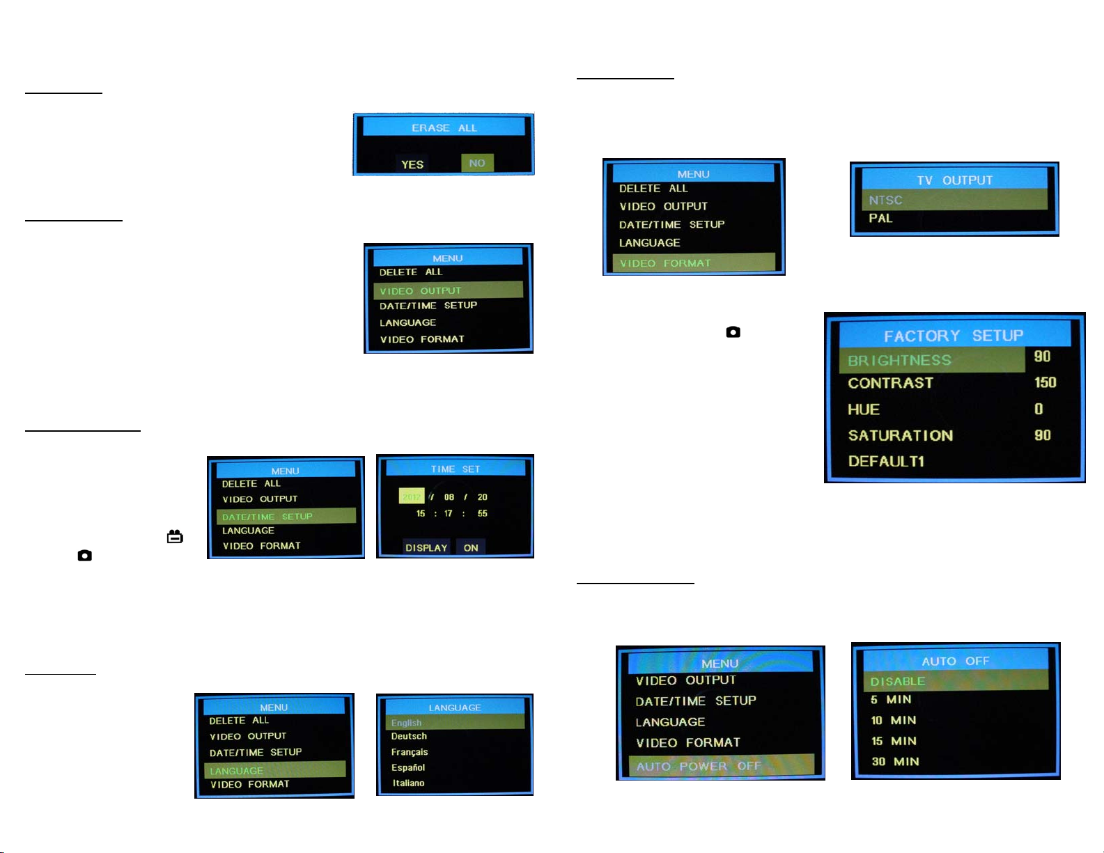
DELETE ALL
Deletes all saved files, video and still photos.
When this function is selected, the unit displays a
frame which includes two options. Use and
to select “Yes” or “No” and press OK to confirm.
VIDEO OUTPUT
This function transfers the video signal to and from
an auxiliary display using the supplied cable. The
unit will automatically switch to the auxiliary
display when the cable is connected and will revert
to the built in display when the cable is
disconnected. This function will allow you to
toggle between displays if both are connected.
Simply press OK while this function is selected to
toggle between displays.
DATE/TIME SETUP
Sets the date and time.
Select this function and
use the and buttons
to select year/month/day
or hour/minute/second
fields, then press the
and/or buttons to
scroll through the numbers to set the date and time. If “DISPLAY” indicates
“ON” status, the date and time will be displayed on the screen. Captured
images will always include a time/date stamp. Confirm changes by pressing
OK.
LANGUAGE
If your unit is supplied
with a language option
this function will allow
you to select English or
the optional language.
Use and to select
and press OK to confirm.
18
Hawkeye®Pro Videoscope – Operation
VIDEO FORMAT
This function allows you to choose the format of the output video signal for an
auxiliary display. The options are NTSC and PAL. Use the and to select
and press OK to confirm.
While the TV OUTPUT options are
displayed, pressing the button
will display the FACTORY SETUP
menu. Here the factory settings for
the video display may be changed or
reset. Use and and press OK to
select the property to be changed.
Then use and to change the
setting and OK to confirm. Holding
the or buttons down for a
couple of seconds will cause the
settings to change more rapidly. Each unit is optimized from the default
settings by Gradient Lens Corp. prior to shipping. These optimized settings
appear on a label on the main unit should they need to be re-entered.
AUTO POWER OFF
Use the and buttons to select time for auto power off or to disable the
auto power off function. Press OK to confirm.