Switching
Capability 20Gbps 40Gbps 56Gbps
Forwarding
Rate 14.88M packets per second 29.76M packets per second 41.66M packets per second
Packet Buffer 4.1MB
Switching
●8K static, dynamic and filtering MAC addresses
●4K VLANs, port-based VLAN, IEEE 802.1Q VLAN tagging, voice VLAN
●VLAN virtual interface
●8 link aggregation groups
●Spanning tree, 16 instances for MSTP
Multicast IGMP Snooping, MLD Snooping
QoS/ACL
●Auto detection and prioritization of voice/video/RTP/SIP/other latency-sensitive packets
●Port priority
●Priority mapping
●Queue scheduling, including SP, WRR
●Traffic shaping
●Rate limit
●1.5K ACL for Ethernet, IPv4 and IPv6
DHCP Option 82, 60,160 and 43
Maintenance CPU and memory monitoring, SNMP, RMON, LLDP&LLDP-MED, backup and restore, syslog, alert, diagnostics
including Ping, Traceroute, port mirroring
Security
●User hierarchical management and password protection, HTTPS, SSH, Telnet
●802.1X authentication
●AAA authentication including RADIUS, TACACS+
●Storm control
●Port isolation, port security, sticky MAC
●Filtering MAC address
●IP source guard, DoS attack prevention, ARP inspection
●DHCP Snooping
●Loop protection including BPDU proctection
●Kensington Security Slot (Kensington Lock) support
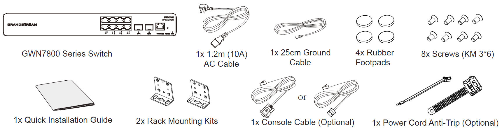
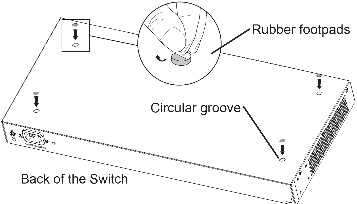
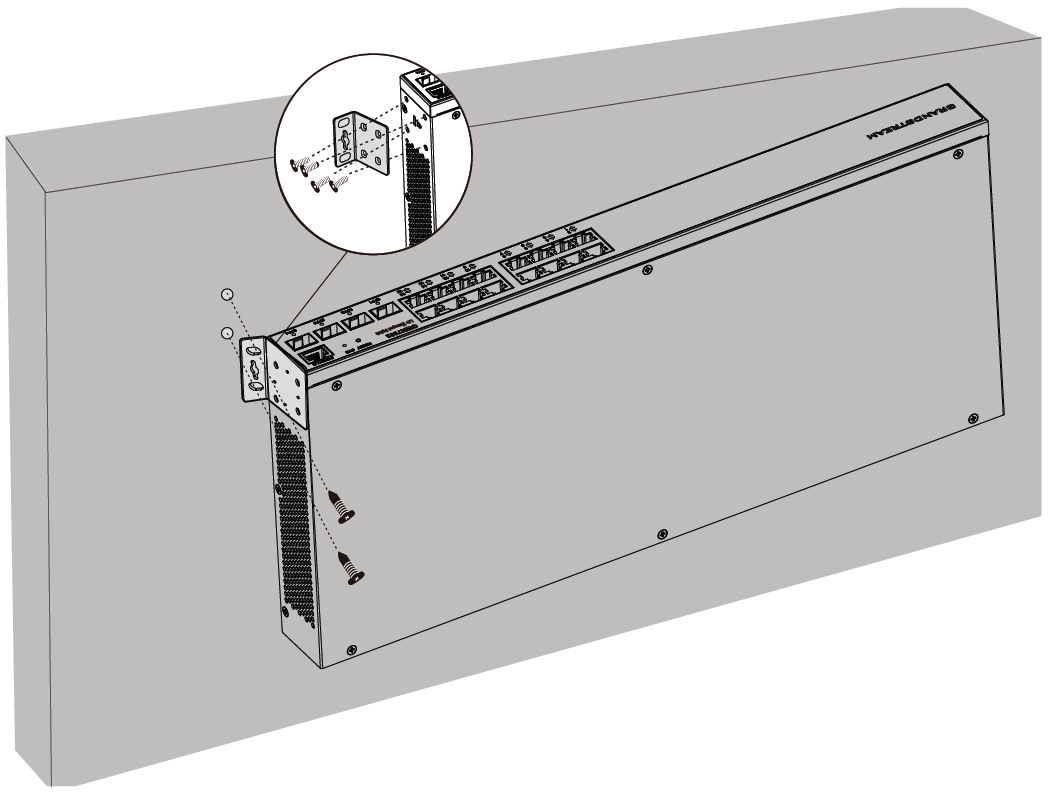
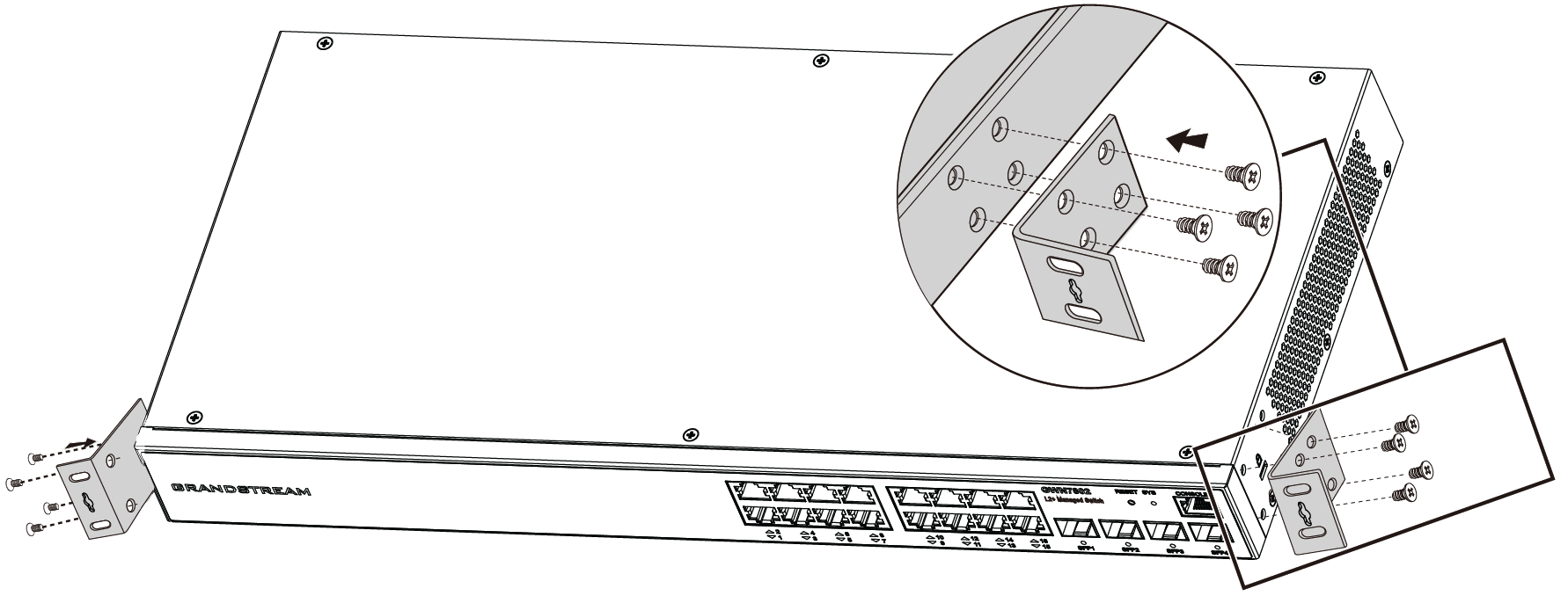
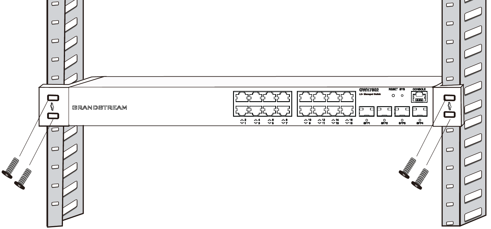
Mounting Desktop/ Wall-Mount Desktop, wall-mount, or rack-mount (rack-mount brackets included)
LEDs
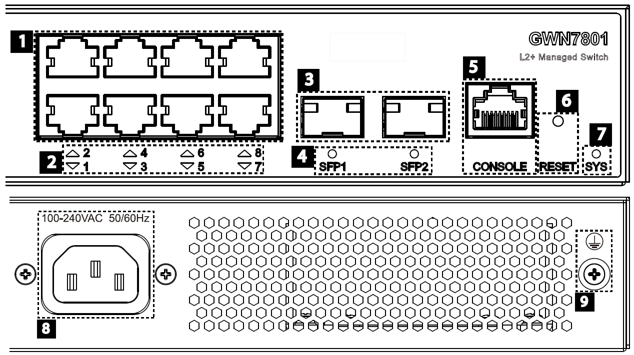
1x tri-color LED for device tracking and status indication
10x green
LEDs for
data ports
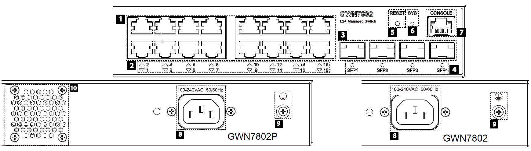
10x green LEDs
for data ports, 8x
yellow-color
LEDs
for PoE ports
20x green
LEDs for
data ports
20x green LEDs
for data ports, 16x
yellow-color LEDs
for PoE ports
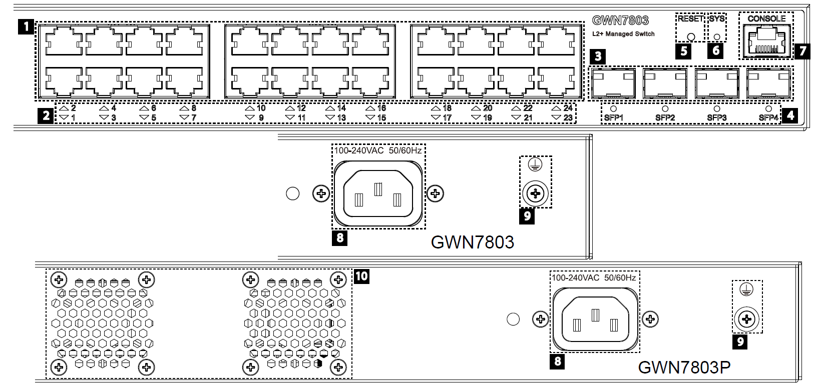
28x green
LEDs for
data ports
28x green LEDs
for data ports, 24x
yellow-color LEDs
for PoE ports
Fan / / / 1 / 2
Environmental Operation: 0°Cto 45°C, humidity 10-90% RH(Non-condensing)
Storage: -10°C to 60°C, humidity: 5% to 95%(Non-condensing)
Dimensions 300mm(L)*175mm(W)*44(H) 440mm(L)*200mm(W)*44mm(H)


