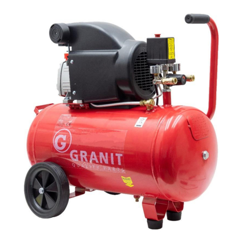
Granit 61099050 User manual

Operating Instructions
Pump
61099050
These operating instructions must be read thoroughly before use and followed. These Operating
Instructions must be retained for future reference.
Translation of the original operating instructions

Compressor Operating Instructions
61099050
2
Table of contents
1. About these operating instructions and symbol descriptions................................... 3
2. Safety and accident prevention rules .................................................................. 3
3. Performance specifications ................................................................................ 5
3.1. Intended use ................................................................................................ 5
3.2. Technical data .............................................................................................. 5
3.3. Main components .......................................................................................... 6
3.4. Getting the machine ready for operation .......................................................... 6
3.5. Oil level ....................................................................................................... 7
4. Compressor operation....................................................................................... 8
4.1. Preparation for use ........................................................................................ 8
4.2. Using the compressor .................................................................................... 9
4.3. Operating a pressure tank .............................................................................10
4.4. Operation at cold temperatures......................................................................10
4.5. Operating the equipment ..............................................................................11
4.6. Switching off the compressor .........................................................................11
5. Maintenance and care ......................................................................................12
5.1. General maintenance instructions...................................................................12
5.2. Maintenance plan .........................................................................................12
5.3. Cleaning......................................................................................................13
5.4. Cleaning/replacing the air filter ......................................................................13
5.5. Draining condensate .....................................................................................13
5.6. Oil replacement............................................................................................14
5.7. V-belt tension ..............................................................................................14
6. Storage and transport......................................................................................15
7. Disposal .........................................................................................................15
8. Fault rectification ............................................................................................16
9. Component drawing with installation position......................................................17
10. Spare parts and parts list .................................................................................18
11. EG Declaration of Conformity ............................................................................20
12. Warranty........................................................................................................21
13. Addresses ......................................................................................................21
14. Legal notice ....................................................................................................21

Compressor Operating Instructions
61099050
3
1. About these operating instructions and symbol
descriptions
The information in these Operating Instructions is labelled as follows:
ATTENTION
Warning of personal injury or environmental damage. Incorrect
operation can lead to serious injury or death.
IMPORTANT
Warning of property damage. Incorrect operation or negligence
may result in personal injury, damage to the equipment or
faulty measurements.
NOTE
Additional information. Instructions and tips for operation.
Numbers in illustrations (1, 2, 3 ...) refer to the corresponding numbers in brackets
(1), (2), (3) ... in the text next to the item numbers in the tables.
Instructions for which the order must be followed are numbered (1, 2, 3, ...).
Lists are marked with bullet points (●, ●, ...).
Symbol labels on the device with their meaning:
Wear hearing protection when operating the machine.
EU conformity symbol
Caution, danger from electric current.
Warning of automatic start-up.
Warning of hot surfaces.
2. Safety and accident prevention rules
These operating instructions were prepared so that you can work safely with the
equipment.
People who are not familiar with these instructions should not perform these actions.
Read these Operating Instructions thoroughly before use. Pay particular attention to the
safety instructions.
These Operating Instructions are intended for people with basic technical understanding of
the use of equipment such as that described here.

Compressor Operating Instructions
61099050
4
If you have no experience with such equipment, you should first get assistance from
experienced people.
Keep all supplied documents with the equipment for future reference if required. Keep the
purchase receipt for any warranty claims.
If you lend or sell the equipment, supply all documentation with it.
Observe the operating and maintenance instructions found in this manual.
Maintenance should be performed at the prescribed intervals and in the prescribed scope.
Following maintenance work, all dismantled protective devices must be properly
reinstalled. The protective devices and their protective functions should be inspected by a
competent person before using the machine.
Defective equipment must be repaired promptly in order to minimize the extent of damage
and avoid endangering the safety of the equipment.
The compressor may only be used and operated under the conditions laid down in these
operating instructions.
Retrofits, changes or modifications to the equipment are strictly prohibited. They require
consultation with and written approval by the manufacturer.
If during operation (residual) hazards and risks become apparent which are not described
in this manual, the operator is obliged to report this to the manufacturer.
Do not change the setting of the safety valve. Before each use, check that the equipment
is functioning properly and that the lines are not leaking.
Compressed air under high pressure can cause severe or fatal injury! If injured contact a
physician immediately!
Before each use always perform a visual and a function check of the equipment to identify
damage and worn parts, and arrange for their repair by trained personnel before use.
After opening the packaging check that all components are complete and undamaged. If
components are missing or damaged, contact your dealer immediately and use the device
only after approval by the dealer.
Warning: Clogged oil filters or valve failure will result in insufficient lubrication.
Make sure that the oil cooling devices are kept clean and that the protective equipment
remains in working order.
Warning: All hoses and fittings of road-driven compressors must be suitable for use on
construction sites at the maximum allowable pressure.
It is recommended that feed hoses be fitted with a safety cable, e.g. a wire rope, for
pressures above 7 bar.
The machine must always be placed on a level and horizontal surface and may not be
tilted.

Compressor Operating Instructions
61099050
5
3. Performance specifications
3.1. Intended use
The compressor is an oil lubricated air compressor. The ambient air is sucked in via the intake
filter and cleaned. The air drawn in is then compressed in the cylinder. The compressed air
flows into the pressure tank and is now available to supply the connected compressed air
tools. This compressor is designed exclusively for compressing air.
NO flammable gases and/or paint and dust mist may be sucked in with this compressor. It
may not be used in potentially explosive atmospheres as this may lead to serious or fatal
accidents with high material damage.
The suction of flammable gases etc. can lead to deflagration and explosions. This can
result in serious to fatal injuries and extensive damage to property!
The compressor has a finger guard and is thus protected against the penetration of medium-
sized foreign bodies (from Ø 12.5 mm).
It is not protected against the penetration of liquids. Therefore the equipment must not be
used in damp or wet rooms or outdoors in the rain. Always ensure that it is stored and used
in a dry place.
Penetration of foreign bodies and liquids can damage the unit and considerably
reduce its performance and service life.
Any other use or use that exceeds this is considered as not in accordance with the intended
purpose.
3.2. Technical data
Performance
Capacity
pressure
Cylinder
Nr.
Model
Code
kW
PS
m³/min
cfm
MPa
Psi
Number
1
Z-0.036/7
cA51
0,55
0,75
0,036
1,3
0,7
102
1
2
V-0.08/7
VA51
1,1
1,5
0,08
2,8
0,7
102
2
3
Z-0.12/8
cD51
1,5
2
0,12
4,3
0,8
116
2
4
Z-0.17/7
VA55
1,5
2
0,17
6,0
0,7
102
2
5
V-0.25/7
VA65
2,2
3
0,25
8,9
0,7
102
2
6
W-0.36/7
TA65
3
4
0,36
12,8
0,7
102
3
7
V-0.48/7
VA80
4
5,5
0,48
17,0
0,7
102
2
8
W-0.67/7
TA80
5,5
7,5
0,67
23,8
0,7
102
3
9
V-0.67/7
VA100
5,5
7,5
0,67
23,8
0,7
102
2
10
W-0.9/7
TA100
7,5
10
0,9
31,9
0,7
102
3
11
W-1.4/7
TA120
11
15
1,4
49,6
0,7
102
3
The unit may not be used in explosive atmospheres. The compressor may only be operated
at ambient temperatures between 5-40 °C.
The suction of flammable gases etc. can lead to deflagration and explosions. This can
result in severe to fatal injuries and extensive damage to property.

Compressor Operating Instructions
61099050
6
3.3. Main components
Figure 1
The compressor is supplied with a pre-set pressure valve control. The operating and switch-
on pressure can be controlled via the setting options.
The maximum permissible pressures and flow rates must not be exceeded under any
circumstances.
If the permissible operating pressures and flow rates are exceeded, this can lead to
serious accidents and damage to property.
3.4. Getting the machine ready for operation
To disconnect the compressor from the mains completely, the unit must be switched off using
the switch (Fig. 2) and then disconnected from the mains by pulling the mains plug.
The compressor can only be prepared for operation by people with sufficient technical
expertise. All other operators must have the installation commissioned by a specialist.
Never loosen parts of the compressor while there is still compressed air in the container.
Sudden pressure release can lead to operating conditions that are difficult to control
and can cause serious injuries.
Never work on the compressor circuit without disconnecting the mains plug. Only operate the
compressor with the stipulated mains voltage. Never use cables that are longer than 5 m or
have a diameter of less than 4 mm². Never pull out the mains plug to switch off the
compressor, but rather press the “off” switch (Fig. 2). If the supply line is not long enough, a
longer pressure hose is recommended.
Touching live components can lead to current flowing through the body and thus to
fatal injuries.
1. Main compressor
2. Pressure valve control
3. Release valve 1
4. Regulator valve
5. Pressure gauge
6. 1-way valve
7. Drain valve
8. Wheel
9. Vent pipe
10. Compressed air tank
11. Safety valve
12. Motor cover
6
2
9
4
12
5
8
1
11
3
7
10

Compressor Operating Instructions
61099050
7
Varying device voltage or fluctuations in voltage can lead to operating faults and
reduce the service life of the device.
If the respective drain valve (Fig. 2 1 or 2) does not work once the motor has been switched
off, you should rectify the problem immediately. If this is not done, the motor could be
damaged when the compressor is switched on again. To do this, follow the instructions for
correcting malfunctions in Chapter 8 of this manual.
Failure to observe the safety instructions can result in damage to property and
personal injury.
Before the compressor is restarted with the reset button, check why it is no longer running
(pressure must always remain below 0.8 MPa). See Chapter 8 Troubleshooting if errors occur.
3.5. Oil level
The oil level of the compressor oil must be kept in the red indicator circle of the sight glass
(Fig.4 no. 13).
Recommended compressor oil:
SAE30 or L - DAB 100 for temperatures >10 °C
SAE10 or L - DAB 68 for temperatures <10 °C
If the wrong oil is used or the oil level is incorrect, this can damage the compressor
and negatively affect the performance of the unit.
Fill up oil and drain off:
Use a screwdriver to remove the cover of the oil filler opening at the top of the crankshaft
housing. If necessary, top up with compressor oil or oil of the quality specified here.
To get the correct oil level the compressor should be placed on a flat load-bearing
surface with wheels and support feet.
Always use the same type of oil. Never mix different types of oil.
Observe the oil level indicated in the sight glass at the front of the housing. The centre of the
red marking shows the correct oil level. Before operating the compressor, close the oil filler
opening again. To drain the compressor oil, unscrew the oil drain plug underneath the sight
glass.
Make sure the unit cannot be switched on if the oil has been drained. Switching the
compressor on without oil can damage it.

Compressor Operating Instructions
61099050
8
4. Compressor operation
4.1. Preparation for use
The following checks must be carried out before using the machine:
Make sure that all bolts and nuts are fully tightened. If necessary tighten the nuts!
Make sure that the area where the compressor is used is clean, dry and well ventilated.
Make sure that the electrical voltage is constant and does not deviate from the prescribed
voltage by more than 4%.
Open release valve 1 or 2 before the first start. Pull the switch to “on”. Let the compressor
run for 10 minutes without load to check that all moving parts are lubricated
Test the tension on the V-belt. Position 2 fingers centrally on the belt and press down.
The V-belt is correctly tensioned when it can be pressed down approx. 10 - 15 mm.
Make sure that the oil level is within the red indicator circle.
Recommended compressor oil:
SAE30 or L - DAB 100 for temperatures >10 °C
SAE10 or L - DAB 68 for temperatures <10 °C
Open the release valve before the first start. Turn the switch to “on”. Let the compressor run
for 10 minutes without load to check that all moving parts are lubricated.
Figure 2
The left pressure gauge is used to read the working pressure and the right pressure gauge
shows the current boiler pressure of the container. Adjustable compressed air can be tapped
via the release valve 1 with the quick coupling. Release valve 2 is also equipped with quick
coupling and provides unrestricted compressed air.
Pressure control
valve
Safety valve
On/off switch
Release valve 1
Release valve 2
2
-+

Compressor Operating Instructions
61099050
9
4.2. Using the compressor
The compressor is controlled by a pressure valve when it is in operation. When the set or
maximum permissible pressure is reached, the motor automatically switches off. It restarts
automatically once a previously set, lower pressure has been reached.
Start the compressor by lifting the on/off switch (see Fig. 2).
It is recommended that the unit be run once until the maximum boiler pressure has been
reached and the unit switches off automatically. Only then should the desired air tools be
connected.
As soon as the motor is switched off, the air in the vent pipe above the relief valve should be
vented. This prevents damage to the motor on restart.
The set pressure can be adjusted using the adjusting screw (Fig. 3). However, this should not
be done without a good reason and the permissible operating pressure of the compressor
should never be exceeded.
If the permissible operating pressure is exceeded and safety switches and valves are
manipulated, this could result in uncontrollable operating conditions. Failure of the
components can lead to serious accidents and extensive damage to property.
The outlet pressure can be adjusted via the adjustment valve. Pull the knob upwards and turn
it counter-clockwise or clockwise to reduce or increase the pressure (Fig. 2).
To stop the compressor, press the switch shown in Figure 2.
Figure 3
Adjusting bolt

Compressor Operating Instructions
61099050
10
If add-on parts and supply lines lack the necessary stability, they can fail as a result
of overloading, causing accidents where people are injured.
To prevent supply lines from swinging around uncontrollably due to unintentional
loosening, these lines/hoses should be secured with a rope or suchlike.
During operation, the compressor surfaces can become particularly hot. Avoid
touching these components. To prevent fires, these surfaces must stay uncovered
and must be cleaned immediately of dust and deposits. Before any maintenance work
is carried out and before it is stored, the compressor should be completely cooled
down.
Carefully release the hose coupling. When you release the hose coupling, hold the coupling
piece of the hose firmly with your hand to avoid injuries due to the hose springing back.
4.3. Operating a pressure tank
Anyone operating a pressure tank must maintain it in a proper condition, operate it properly,
monitor it, carry out necessary maintenance and repair work without delay and take the safety
measures that are needed under the circumstances.
In individual cases, the competent supervisory authority may order the necessary monitoring
measures.
A pressure tank may not be operated if it has defects that endanger employees or third
parties.
The pressure tank must be checked regularly for damage, e.g. rust. If you discover any
damage, contact your specialist dealer immediately.
4.4. Operation at cold temperatures
At low temperatures, the oil in the crankcase becomes thick and viscous, which can lead to
start-up problems.
If necessary, do the following when operating your compressor in the colder seasons:
1. Let the pressure in the boiler run down to zero.
2. Open the water drain screw at the bottom of the boiler (Fig. 2 no. 7).
3. Switch on the compressor by pulling up the on/off switch (Fig. 2).
4. Let the compressor run for 2-3 minutes with the water drain screw open. During this time
the unit heats up.
5. After the warm-up time has elapsed, close the water drain screw again.
6. Now the boiler can fill or build up pressure.
If the compressor still does not start, place it in a temperature-controlled room for
about ½-1 hour so that it can warm up.

Compressor Operating Instructions
61099050
11
4.5. Operating the equipment
Press the plug nipple of the compressed air hose into the respective quick coupling of the
compressor. It locks automatically. To remove the compressed air hose, push the outer
coupling ring on the quick coupling towards the pressure reducer.
When opening the quick coupling, prevent the compressed air hose from springing back
uncontrollably by holding it firmly.
The rebounding hose can hit people and injure them.
The effective air output is approx. 60-70% of the intake capacity, which defines the capacity
of the compressor.
When working with air tools, observe the manufacturer’s specifications for the required
working pressure and air consumption. You can set the operating pressure with the pressure
reducer.
Excessive working pressure leads to increased equipment wear without increasing the working
performance.
To increase the working pressure:
Turn the setting wheel of the pressure reducer (see Fig. 2) in the + (plus) direction to increase
the working pressure.
To reduce the working pressure:
Turn the setting wheel of the pressure reducer (see Fig. 2) in the - (minus) direction to reduce
the working pressure.
4.6. Switching off the compressor
To switch off the compressor, press down the on/off switch (see Fig. 2). The unit must never
be switched off by pulling out the mains plug.
Pulling out the mains plug without first pressing down the button on the pressure
switch deactivates the pressure relief. If the compressor is not in use, the operating
pressure will damage the compressor.
Unplug the unit from the mains socket when you no longer need to use it.

Compressor Operating Instructions
61099050
12
5. Maintenance and care
Before any maintenance and servicing work is carried out, the compressor must be
completely disconnected from the mains and depressurised. Residual voltages and
pressures can lead to uncontrollable operating conditions and cause severe or even
fatal injuries.
Covers and protective grids must be replaced immediately after maintenance work
has been carried out. If any covers are missing, this can lead to serious accidents
where people can be injured.
5.1. General maintenance instructions
•Maintenance and repair work may be performed only by qualified personnel.
•Use only original spare and wear parts.
•Maintenance, cleaning and repair are permissible only when the system is not under load.
•If a paint touch-up is necessary, make sure not to obscure the instruction and product
signs. If necessary, replace them with original spare parts.
•Fasteners must be regularly checked for tightness, and tightened as necessary.
Never perform different kinds of work at the same time and with multiple people.
Failure to follow maintenance instructions can lead to serious accidents and
malfunctioning.
Do not let any part of the body get between moving parts.
Failure to follow the lubrication instructions can cause damage and malfunctions.
5.2. Maintenance plan
The following maintenance work must be performed to maintain the performance and
operational safety of the unit for as long as possible.
•After the first 10 operating hours the crankcase should be cleaned and the oil renewed.
•The oil level (Fig. 4 no. 13) should be checked every 20 operating hours and refilled if
necessary.
•The drain tap (Fig. 1 no. 7) below the tank should be opened every 60 operating hours
to remove condensation water.
•Every 3 months the crankcase and air filter should be cleaned and the oil should be
changed.
•The safety valve and pressure gauge should be checked by a specialist every 6 months.
Make sure that the tank is not damaged or rusty.

Compressor Operating Instructions
61099050
13
Every full year the wall thickness of the tank should be checked by a specialist. The wall must
not be thinner than 2.1 mm.
5.3. Cleaning
To protect the compressor from contamination, it should be covered with a plastic film after
each use.
•Only clean the compressor when it has cooled down.
•Only clean the compressor with a dry, soft cloth or with compressed air.
•Never use harsh and/or scratchy cleaning agents.
5.4. Cleaning/replacing the air filter
The air filter prevents dust and dirt from being sucked in.
A clogged air filter considerably reduces your compressor’s performance and service life.
Therefore, depending on the degree of soiling, the air filter must be cleaned regularly and
replaced with a new filter if necessary
Proceed as follows:
1. Remove the air filter by unscrewing it from the air intake opening.
2. Open the air filter housing and remove the foam filter.
3. Clean the foam filter. Do not use any cleaning agents for cleaning.
4. If the foam filter can no longer be cleaned, it must be replaced with an original spare part.
5. Insert the new or cleaned foam filter into the housing.
6. Screw the complete air filter back into the corresponding air intake opening.
Never operate the compressor without an air filter insert, as this can damage the
compressor.
5.5. Draining condensate
Condensation water collects at the bottom of the boiler. Drain the condensate at least once
a week. To do this, open the drain screw at the bottom of the boiler (Fig. 1 no. 7) until
there is no more water in the air coming out.
The condensation water may only be drained when the boiler is under pressure.
The condensate contains oil residues and must be collected and disposed of according
to regional regulations.

Compressor Operating Instructions
61099050
14
5.6. Oil replacement
Check the oil level regularly and top up compressor oil if necessary. The optimum oil level can
be read off the sight glass (Fig. 4 no. 13). The optimum oil level is shown by the red marking.
If the red mark is exceeded, there is too much oil in the tank.
An oil level that is too high or too low will cause damage to various compressor parts
and also contaminate the discharge air.
The first oil change should be carried out after 20 operating hours.
All subsequent oil changes should be carried out after 200 operating hours but at the latest
after one year.
How to change the oil:
1. Let the compressor warm up.
2. Switch off the compressor by pressing the pressure switch (Fig. 2) downwards.
3. Disconnect the power supply by pulling the mains plug out of the socket.
4. Have a suitable container for collecting the used oil ready.
5. Open the oil drain screw below the sight glass (Fig. 4 no. 13) with a ring or socket spanner
and let the used oil drain completely
The waste oil must be collected and disposed of as required by regional waste
management regulations. Improper disposal can cause considerable damage to the
environment.
6. Retighten the oil drain plug firmly after the used oil has all drained off.
7. Pour new oil into the filling opening. Make sure to observe the information on the oil level
in chapter 3.5.
8. Close the filling opening with the plug provided for this purpose
Always use the same type of oil. Never mix different types of oil. You need about
0.25 litres of compressor oil for an oil change. When you pour in the new oil, make
sure to check the oil level in the sight glass.
5.7. V-belt tension
If the belt tension deviates from the default deflection of 10-15mm, it must be corrected by
moving the motor on the compressor console.
Incorrect belt tension and misalignment can lead to increased belt wear and
mechanical damage to the drive parts.
Before the belt tension is checked or the V-belt is adjusted, the compressor must be
switched off and disconnected from the mains. Uncontrolled starting can lead to
serious injuries.
1. After switching off and disconnecting from the mains, the four screws on the motor
console are easily loosened so that it can be moved.
2. Once the correct belt tension has been obtained, the four screws must be tightened
again.

Compressor Operating Instructions
61099050
15
3. Before restarting, check the belt tension and the alignment of the V-belt pulleys. If
there are deviations, repeat the adjustment.
6. Storage and transport
Use the transport bracket. Only move the unit using the transport bracket provided.
Always store the compressor in a dry and frost-proof room. If the compressor is not used for
a longer period of time, switch it off when it is completely disconnected from the power supply
and relieved of pressure.
Always store the compressor on a horizontal level.
Always check the condition of the unit before it is stored and carry out maintenance before
shutting it down so that the compressor is quickly ready for use again.
7. Disposal
The separate, environmentally friendly disposal of materials encourages recycling of
materials. Therefore, after expiry of the normal service life, the equipment itself and all related
components, including the lubrication, packaging and wear parts, should be disposed of at a
recyclables collection point.
Packaging, equipment and accessories are made of recyclable materials and should be
disposed of accordingly.
If the unit is no longer serviceable, make sure it is unusable before disposal.
If you do not have the necessary technical knowledge, hire a specialist to dismantle
and dispose of the unit. RISK OF INJURY!
!!! Always observe local disposal regulations !!!

Compressor Operating Instructions
61099050
16
8. Fault rectification
Malfunction
Possible cause
Remedy
Motor cannot be started,
runs too slowly or becomes
too hot.
1. Insufficient voltage or error in the
circuit
2. Power cable too long or too thin
3. Pressure switch malfunction
4. Motor fault
5. Main compressor stuck
1. Check circuit
2. Replace cable
3. Repair or replace switch
4. Repair or replace
5. Check and repair
Compressor blocked.
1. Overheated moving parts due to
inadequate lubrication.
2. Moving parts damaged or blocked
due to foreign bodies.
1./2. Check crankcase, bearing, piston
rod, piston ring and piston and replace if
necessary.
Compressor vibrates
heavily and/or makes
untypical noises.
1. Connector has come loose.
2. Foreign matter in the compressor.
3. Piston hits the valve seat.
4. Moving parts worn out.
1. Check and re-fasten.
2. Check and remove foreign body.
Insufficient pressure build-
up
or reduced ventilation.
1. Motor running too slowly.
2. Air filter clogged.
3. Safety valve leaking.
4. Ventilation pipe leaking.
5. Seal damaged.
6. Valve plate damaged or
accumulation of soot.
7. Piston ring and cylinder worn or
damaged.
1. Check and rectify.
2. Clean or replace filter.
3. Check and replace the valve.
4. Check and repair.
5. Check and replace.
6. Replace and clean.
7. Repair or replace.
Oil consumption too high.
1. Oil level too high.
2. Vent pipe blocked.
3. Piston ring and cylinder worn out.
1./2./3. Keep oil level at correct level
Check and clean.
Troubleshooting requires technical expertise and the availability of intact tools and
operating materials. If you do not have all these means at your disposal, you should
always have the unit checked by a specialist and have the faults rectified.
The first step for abnormal operating conditions is always to switch off and
disconnect the power supply.

Compressor Operating Instructions
61099050
17
9. Component drawing with installation position
Figure 4

Compressor Operating Instructions
61099050
18
10. Spare parts and parts list
Position no.
Description
Order number
Quantity
1
Screw M6×45
61099050/1
8
2
Spring washer 6
61099050/2
8
3
Three-angle connector
61099050/3
1
4
Cylinder head
61099050/4
2
5
Cylinder head gasket
61099050/5
2
6
Valve plate
61099050/6
2
7
Valve disc
61099050/7
2
8
Gasket
61099050/8
2
9
Valve gasket
61099050/9
2
10
Cylinder Ø 65
61099050/10
2
11
Cylinder gasket
61099050/11
2
12
Piston ring Ø 65×2
61099050/12
2
13
Oil scraper ring Ø 65×3
61099050/13
4
14
Piston Ø 65×35.5
61099050/14
2
15
Circlip Ø 14
61099050/15
2
16
Piston pin
61099050/16
4
17
Connecting rod
61099050/17
2
18
Ventilation pipe
61099050/18
1
19
Crankcase
61099050/19
1
20
Right-angled connecting
piece
61099050/20
1
21
Oil level gauge G1/2
61099050/21
1
22
Oil drain plug
61099050/22
1
23
Nut M8
61099050/23
4
24
Spring washer 8
61099050/24
8
25
Screw M8×32
61099050/25
8
26
Bearing 6204-2RS
61099050/26
1
27
Crankshaft
61099050/27
1
28
Bearing 6205-2RS
61099050/28
1
29
Sealing ring
61099050/29
1
30
Mounting plate
61099050/30
1
31
Bearing bracket
61099050/31
1
32
M8×25 bolt
61099050/32
4
33
Washer 10
61099050/33
2
34
Nut M10
61099050/34
2
35
Motor
61099050/35
1
36
Start capacitor
61099050/36
1
37
Operating capacitor
61099050/37
1
38
Capacitor cover
61099050/38
1
39
Screw ST3.9×16
61099050/39
6
40
Reset switch overload
61099050/40
1
41
Pressure line
61099050/41
1
42
One-way valve
61099050/42
1
43
Angle connector Rp1/8
61099050/43
1

Compressor Operating Instructions
61099050
19
Position no.
Description
Order number
Quantity
44
Pressure line
61099050/44
1
45
Pressure vessel
61099050/45
1
46
Wheel
61099050/46
2
47
Belt wheel Motor
61099050/47
1
48
Axle
61099050/48
2
49
Washer 8
61099050/49
1
50
Screw M8×30
61099050/50
1
51
Screw M5×35
61099050/51
3
52
Washer 5
61099050/52
3
53
Spacer
61099050/53
3
54
Protective grille
61099050/54
1
55
Belt
61099050/55
1
56
Compressor belt pulley
61099050/56
1
57
Drain valve 1/4 inch
61099050/57
1
58
Rubber foot
61099050/58
2
59
Handle
61099050/59
1
60
M8×8 screw
61099050/60
4
61
Power cord
61099050/61
1
62
Nut 1/2 inch
61099050/62
1
63
Regulating valve
61099050/63
1
64
Quick coupling
61099050/64
2
65
Safety valve
61099050/65
1
66
Pressure gauge
61099050/66
2
67
Pressure switch
61099050/67
1
68
Air filter
61099050/68
2
69
Connecting cable
61099050/69
1
70
Power cord
61099050/70
1

Compressor Operating Instructions
61099050
20
11. EG Declaration of Conformity
The manufacturer,
Wilhelm Fricke SE
Zum Kreuzkamp 7
DE-27404 Heeslingen
hereby declares on its sole responsibility that the compressor
Type/series identification: 61099050 (V-0.25/8-VD65-50)
is in conformity with the provisions of
2006/42/EC Machinery Directive
The machine also complies with the provisions of the directives 2014/30/EU on
electromagnetic compatibility and 2014/35/EU on electrical equipment EC (protection
objectives were met according to Annex I, No. 1.5.1 of the Machinery Directive 2006/42/EC).
The machine also complies with the 2014/29/EU regulations on simple pressure tanks.
The product was developed in accordance with the following standards:
EN 1012-1:2010 Compressors and vacuum pumps - Safety requirements -
Part 1
Authorised person for documentation:
Mr. Eike Viebrock
Wilhelm Fricke SE
Zum Kreuzkamp 7
DE-27404 Heeslingen
The serial number and model year are shown on the type plate of the equipment.
Heeslingen, 27/05/2021
Translation of the original declaration of conformity
________________________________________
Holger Wachholtz, Board
Table of contents
Other Granit Water Pump manuals
Popular Water Pump manuals by other brands

tefen
tefen MixRite TF25 user guide

GORMAN-RUPP PUMPS
GORMAN-RUPP PUMPS T3A61S-B Installation, operation and maintenance manual

Moro
Moro Air Series Use and maintenance manual

Cembre
Cembre B70M-P24 Operation and maintenance manual

ennos
ennos Sunlight 0.5HP HeP40-L installation manual

GEA
GEA Futuro Instruction manual and installation instructions

Clarke
Clarke IVP13A Operating & maintenance instructions

Bosch
Bosch REXROTH A4 Series instruction manual

vacuubrand
vacuubrand VACUU-PURE 10C Instructions for use

Pentair
Pentair DELTA ENVIRONMENTAL D1C20-21 Series Installation and service manual

Whale
Whale Supersub Series Installation guides

Altrad
Altrad BELLE WPX 3/30 Operator's manual