Granudos 45-S3 User manual

WDT Operating Instructions GRANUDOS 45/100 (S3 - 04/02) Page 1 of 1
_______________________________________________________________________________
Series No..........................Customer..........................................Date of delivery……….……………
Operating instructions GRANUDOS 45/100-S3
Safety Devices
1. Chlorine and acid may not be mixed together
or with other chemicals
Pay attention to the safety devices on
chemical containers
2. The dosing hopper must be screwed even
and firmly to the container
3. Ensure after changing a drum, that it is firmly
fixed in position and the securing systems are
used
4. In service the dissolving system must be
covered with the supplied cover
5. Only instructed personnel may work with the
GRANUDOS
6. Ensure booster pump does not run dry,
always isolate pump when backwashing.

WDT Operating Instructions GRANUDOS 45/100 (S3 - 04/02) Page 2 of 2
_______________________________________________________________________________
TABLE OF CONTENTS
Safety devices
Test certificate
page
1 Function of GRANUDOS 45-S3 2
1.1 Data, Measures, Performance 3
1.2 Drum carrier 3
1.3 Dosing Assembly Chlorine 4
1.4 Acid dosing 4
1.5 Dissolving System 5
1.6 Control Panel (GRD S3) 6
1.6.1 Front plate 6
1.6.2 Dosing control system 7
1.6.3 Dosing performance adjustment 7
1.6.4 Dosing by auto controller 7
2 Installation 8
2.1 Electrical Connection 8
2.2 Providing acid 8
2.3 Tubing 9
3 Start 10
3.1 Deaeration of the water supply tubing 10
3.2 Water level in flushing tank 10
3.3 Water flow/Suction performance of injector 10
3.4 Loading the chemical drum onto machine 10
3.5 Acid dosing 11
4 Irritations Diagnosis 12
4.1 Irritations indicated by red lamps/control switches 12
4.2 Irritations notmonitored/indicated by switches 13
5 Maintenance 13
6 Wiring Diagram/Fuses 14
7 Spare parts list 15
8. Maintenance list 17

WDT Operating Instructions GRANUDOS 45/100 (S3 - 04/02) Page 3 of 3
_______________________________________________________________________________
1. Function of GRANUDOS
1.1. Data, Measures, Performance
The GRANUDOS 45-S3 dosing system comprises:
- main vertical support with rotating drum carrier
assembly
- calcium hypochlorite granules metering
- acid metering equipment
- dissolving system
- control panel
Measures:
base needed: 120x70x180 cm
height: 140 cm
weight: 50 kg
material:
main vertical support and drum carrier:
steel, zinc and powder coated
other parts: PVC, PE
booster pump
centrifugal pump: 0,3 kW, 230 VAC,
supply pressure: minimum 0,2 bar
Water flow: app. 1000 l/h
Dosing Performance:
chlorine: GR 45: 1,5 kg/h. GR 100: 3 kg/h
acid: GR 45: 3 l/h, GR 100: 3 l/h
1 drum 9 type label.
2 2 clamp bands 10 vertical carrier
3 lid curl 11 locker
4 dosing hoper 12 acid pump
5 dissolving system 13 acid carboy
6 drum carrier 14 carboy lance
7 controlsystem 15 water supply with filter
8 conn. Housing 16 heated dosing nozzle
17 dust protection
18 pump cover

WDT Operating Instructions GRANUDOS 45/100 (S3 - 04/02) Page 4 of 4
_______________________________________________________________________________
1.2 The Drum Carrier
The rotating drum carrier assembly (6) is fixed to the main vertical support (10). The drum
(1) with hypochlorite is fixed on the carrier assembly (6) by 2 band clamps (2) and a
retaining belt. The dosing hopper (3) is fixed on the drum in place of the drum lid. The
carrier with the drum is then turned through 180° to the dosing position, the chemical is
dosed into the dissolving system (5) where it is fully dissolved and conveyed by a venturi to
the swimming pool.
1.3 Chlorine Dosing Assembly
19
10 dosing hopper 16 hopper cover
11 dosing motor 17 knocker (option)
12 dosing screw 18 seal washer
13 motor mounting 19 dosing hopper screw ring
14 dosing nozzle heated
15 drum empty switch with adjusting screw and LED
The dosing screw (12) meters the chlorine through the heated dosing nozzle (14) to the
dissolving system. If the drum empty switch (15) is indicating, the LED 4 burns
continuously, dosing is running on,. The knocker (17, optional) gives a hit to the hopper at
each dosing motor run so supporting dosing.
Dosing performance is adjusted by 2 turning knobs at front fascia, see para starting.
1.4 Acid Dosing
The acid is dosed down in the flushing cone (23 - see next para) by the peristaltic pump
which is fitted directly right side at the vertical support. If acid level switch indicates acid
container empty, the GRANUDOS chlorine dosing is stopped too to avoid scaling.
As acid use sulphuric acid 37%. Concentrated hydrochloric acid (HCI) penetrates the pump
hose and will attack the pump rollers and further the pump

WDT Operating Instructions GRANUDOS 45/100 (S3 - 04/02) Page 5 of 5
_______________________________________________________________________________
1.5 Dissolving System
2
0
20 pressure switch (optional) 27 cyclone mixing/dissolving
chamber
21 floating valve 29 level switch
22 flushing tank 30 union bush with nozzle inside
23 flushing tube 31 outlet ball valve
24 suction tube with flow control 32 water supply ball valve
25 venturi nozzle 33 fitting ¼” for test pressure gauge
26 booster pump
The supply water coming from the pool water is divided at the discharge of the booster
pump (26), one way leading to the flushing tank (22), the other branch directed to the
venturi nozzle (25), where the water is drawn out of the flushing tank together with the
dosed chemicals. The supply water flow is controlled by means of a floating valve (21) and
monitored by a flow switch (24), the latter being installed in the suction tube of the venturi.
To mix the chemicals and to ensure the complete dissolving of the hypochlorite granules a
cyclone mixing chamber (27) is fitted after the venturi. Optionally the supply water
pressure is monitored by the pressure switch (20).
21
22
21a
23
29
30
33 34 31 20 24 25 27
32
26

WDT Operating Instructions GRANUDOS 45/100 (S3 - 04/02) Page 6 of 6
_______________________________________________________________________________
To ensure that calcium hypochlorite and acid do not come in contact with each other in the
open tank part of the dissolving assembly a sophisticated control system is installed:
- metering of the two chemicals is regulated with pauses between the metering
intervals (para 4.2 'Adjusting dosing performance').
- power supply for chlorine and acid dosing motors are connected by a relay system so
that only one of them can get power (24VDC).
- flow switch (24) , level switch (29), and optional pressure switch monitoring water
supply and flow conditions. If any non-compliance with the given limits occurs, the
dosing will be switched off.
1.6 Control Panel (GRD S3)
1.6.1 Front plate – service elements
The control board is of analogical type, one part together with the front plate. All
connectors are push type directly on the control board.
Service elements:
On connector housing below:
1 main switch on/off
1 main fuse 3,15 amp slow
On front plate:
1 select switch for dosing by auto controller or for continuous dosing
1 potentiometer knob to adjust dosing cycle from 1 – 8 minutes
2 potentiometer knobs to adjust dosing time of dosing motors chlorine and acid:
100 % = 20 seconds
2 push button switches to test dosing motors of the chemicals: if pushed, dosing is
running accordingly if no fault is indicated.
1 green lamp to indicate service

WDT Operating Instructions GRANUDOS 45/100 (S3 - 04/02) Page 7 of 7
_______________________________________________________________________________
4 red lamps to indicate faults: acid empty, suction venturi low, water level in tank low
(indicated too, if pressure switch is fitted and indicating), water level in tank high,
dosing is stopped in these cases.
1 red lamp to indicate chlorine empty – dosing is not stopped.
Inside on control plate:
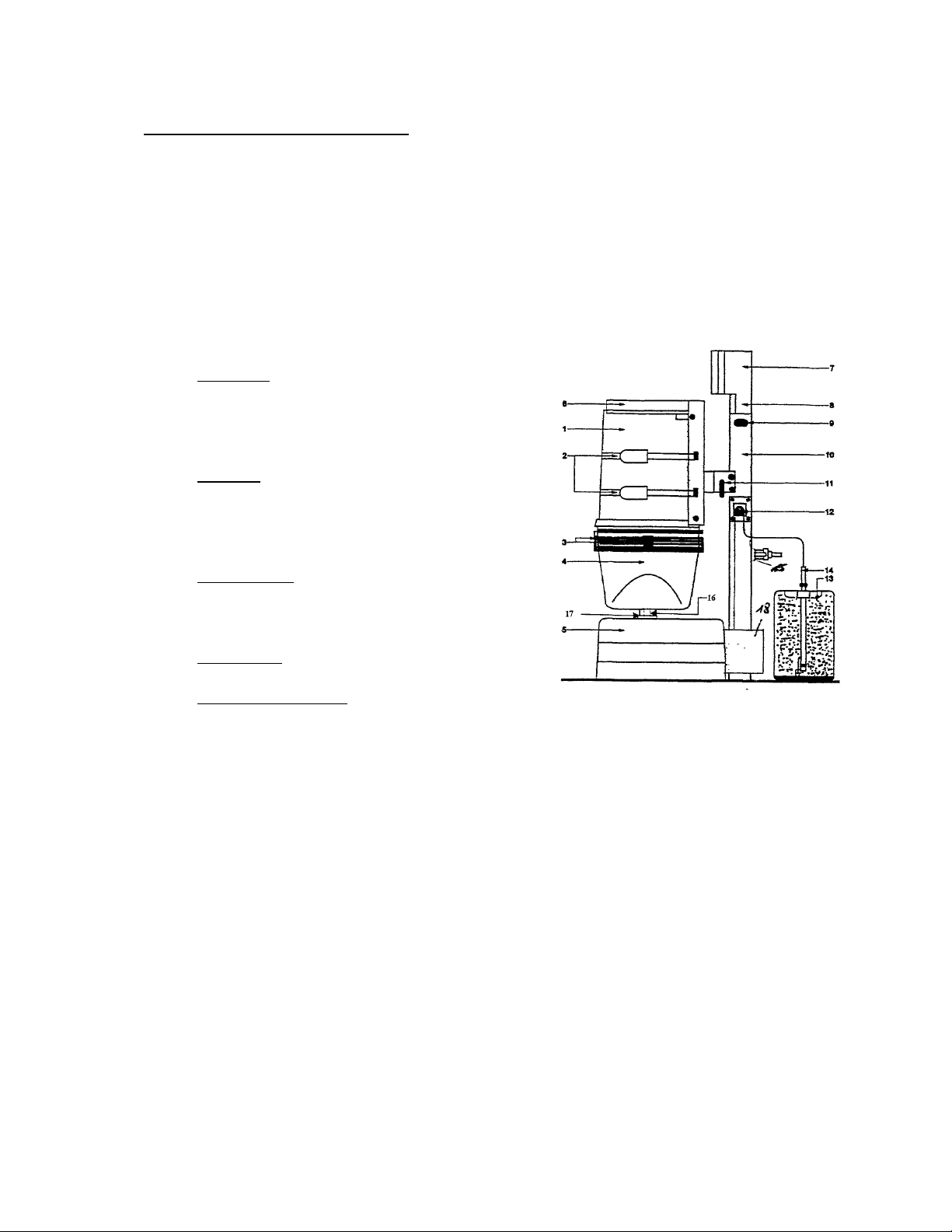
1 primary fuse 1,25 amp slow
1 secundary fuse 315 mA slow for all outputs
dosing motors, switches, relays
The function of the booster pump is not influenced by any fault, only dosing is stopped.
1.6.2 Dosing control system
The dosing performance is set by setting a dosing cycle time (1 – 8 minutes) valid for both chemicals and
a dosing time for each chemical separately (0 – 20 seconds). At continuous dosing all cycle dosing of
chlorine and acid is running as set.
Maximum dosing is got with a cycle of 1 minute and dosing times 100 %, actually: 20 sec dosing acid,
10 sec. pause, …20 sec. dosing chlorine, 10 sec. pause
At setting a longer cycle time, the pause in between the dosings of chlorine and acid are becoming
accordingly longer.
At connecting an external auto controller for free chlorine and pH this dosing cycle is activated, too.
Dosing is running if external control output meets the internal “ability”. To get a sufficient dosing
performance the controller cycle should be in the range of some minutes and the dosing control at the
GRANUDOS should be set to maximum. The auto controller input must be 230 VAC on/off.
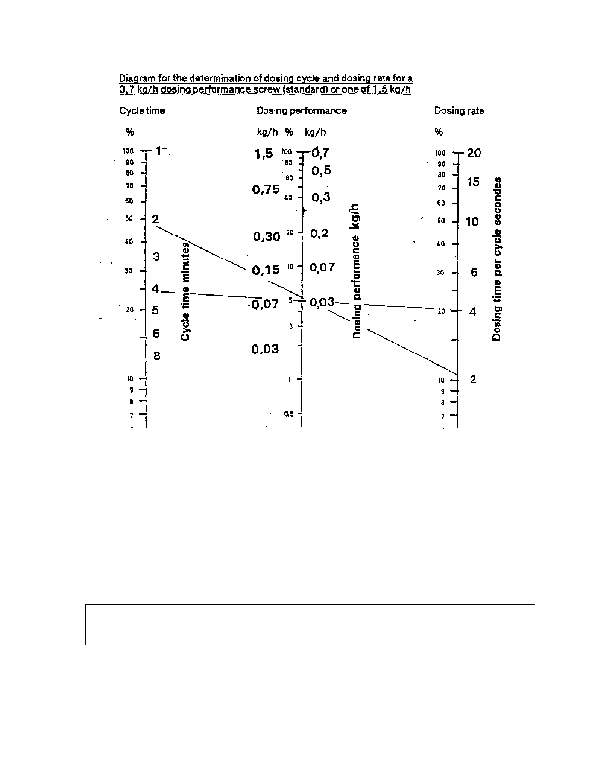
1.6.3 Dosing Performance Adjustment – see diagram next page
1. Chlorine
In principle the chlorine consumption of a pool depends on a variety of influences:
Loading, temperature, wanted chlorine concentration etc. Normally a standard indoor pool
needs about 300 g of calcium hypochlorite per 100 m
3
in volume per day. So a pool of 300
m
3
in volume needs app. 900 g/day or app. 37 g/h at continuous dosing. These 37 g/h
corresponds to 5 % of the maximum dosing performance of 0,7 kg/h. This is achieved with
a cycle time of 2 minutes and a corresponding dosing rate of 10 %. The same dosing
performance is achieved with a cycle time of 4 minutes and a dosing rate of 20 %. See
performance table next page.
An outdoor pool needs at good whether conditions about 3-5 times more chemical
2. Acid
The consumption of acid is harder to predict as that of chlorine. For the beginning set a
dosing performance of same as for chlorine. The actual need has to be found by trial and
error. The pH should be at 7,0 – 7,4.
1.6.4 Dosing Controlled by Auto-Controller

WDT Operating Instructions GRANUDOS 45/100 (S3 - 04/02) Page 8 of 8
_______________________________________________________________________________
Connecting an external auto controller for free chlorine and pH the set dosing cycle is activated,
too. Dosing is running if the control output of the auto controller for free chlorine / pH comes
together with the internal set dosing time. To get a sufficient dosing performance the controller
cycle should be in the range of some minutes (on-off, possibly proportional) and the dosing set at
the GRANUDOS should be at high level or maximum: cycle time 1 minute, dosing 100%.
The auto controller output must be of 230 VAC. See wiring diagram.

WDT Operating Instructions GRANUDOS 45/100 (S3 - 04/02) Page 9 of 9
_______________________________________________________________________________
2. Installation
2.1 Electrical connection
The electrical supply of the GRANUDOS has to be controlled by the electrical supply of the
circulation pumps that dosing can only be with water circulation and accordingly water supply to
the GRANUDOS. The GRANUDOS has to be stopped at back washing, too!
To connect external systems to the GRANUDOS please use only flexible cable type.
Electrical works are only to be executed by authorised people.
2.2 Providing Acid
As acid please use one on base of sulphuric acid (37 – 50 %) preferably supplied in 30-50 kg
transportable containers. If bigger stock containers are used the acid empty switch must be
connected to the GRANUDOS.

WDT Operating Instructions GRANUDOS 45/100 (S3 - 04/02) Page 10 of 10
_______________________________________________________________________________
2.3 Tubing
For satisfactory waterflow through the dissolving system the supply pressure must be at least 0,2
bars. At low service pressure the counter pressure must be low, too. Counter pressure and pressure
loss in the dosing line should be as low as possible. At works the GRANUDOS has been tested at
following pressure conditions:
Service pressure 1,2 bars Counter pressure 1,2 bars
0,6 bars 0,8 bars
0,3 bars 0,5 bars
Within these ranges the GRANUDOS should function well. In addition please pay attention to the
following:
1. Tapping point for supply water to be between filter and heat exchanger, dosing point after
heat exchanger.
2. Ensure that the tapping/dosing points are free flowing and not blocked by scale or
corrosion.
3. Pipe runs to be kept as short as possible. PVC-tubing 25 mm or hose 1´´. For longer
distances or poor pressure conditions use bigger tubing.
4. Use high quality PVC ball valves.

WDT Operating Instructions GRANUDOS 45/100 (S3 - 04/02) Page 11 of 11
_______________________________________________________________________________
3. Start
After having executed points 3.1 to 3.3 open the ball valves at the tapping points and at
GRANUDOS. Press floater of floating valve inside the tank down to let water flow into the
flushing tank. When the flushing tank is half full only then switch on the GRANUDOS mains as
the booster pump of GRANUDOS should not run dry.
To ensure correct dosing water flow through the flushing tank must run in the correct way as
described below.
3.1 Deaeration of the water supply tubing
At switching on the GRANUDOS take care to deaerate the supply water tubing completely. For
this please observe the water level inside the pre-filter. If he get’s empty switch off the
pump/machine and wait till the filter is full again, then switch on again. On operation the filter
must be and stay full of water; a little air at top staying steadily does not matter. The deaeration
procedure can take some minutes depending on the length of the supply tubing.
3.2 Water level in the flushing tank
Water level in the flushing tank should be maintained at half full. To obtain a higher level unscrew
float rod, for a lower level screw in the float rod. One turn gives about 1 cm in level height.
3.3 Water flow/Suction performance of the venturi
At stable water level the switch bobbin of the flow switch inside the suction tube (10) should be
rised up definitely to top, the LED of the switch may not burn.
To adjust the water flow to pressure conditions of filter system a nozzle is inserted in the union
(13c) behind the injector. If water level in the tank tends to run low (too high suction at the
injector) fit the nozzle with the 5,5 mm diameter hole you find in the spare parts kit. If the water
level tends to run high and/or suction is too low – switch bobbin does not rise (too high counter
pressure?) put in the 7 mm nozzle or use without nozzle.
3.4 Loading the chemical drum onto machine
Before carrying out any task involving chemicals the operator should put on the relevant protective
clothing, at least for protection of eyes, breathing, skin and clothing i.e. goggles, respirator, gloves
and apron. As the chemical can be compressed within the conical drum by vibration on transport
and this could make problems at dosing, please roll the drum on the floor before loading.
1 Before loading the drum onto machine the dosing hopper should be fitted on to the drum:
2 Position the drum on the floor, adjacent to the machine within comfortable reach of the
hopper cable i.e. do not strain the cable. The two handles of the drum are sidewards from
your position.
3 Screw off the drum lid. Remove the blue plastic scoop from inside the drum.
4 Position the dosing hopper on the open drum so that the cable is coming on right side after
screwing the hopper onto the drum. Ensure that the hopper curl ring fits well to the drum.
5 . Ensure that the drum carrier is in the upright position and ready to receive the drum i.e.
that it is locked in this position (locking device 7).
6 Load the drum, carefully, onto the drum carrier so that the cable is at right. This may be
lifted manually, but ensure no injury to the back by lifting properly – or better still
use a GRANUD0S drum lifter.

WDT Operating Instructions GRANUDOS 45/100 (S3 - 04/02) Page 12 of 12
_______________________________________________________________________________
7 Ensure that the drum is standing upright and symmetrically on the drum carrier, touching
the rear rails being with the drum edge below the retaining rod.
8 Fix the drum securely in position using the drum band clamps. Adjust the clasp tension by
adjusting the nut on the screwed end at left end of the band clamps. These screwed ends are
located in the lugs on the rear of the drum carrier. Lock the clamp clasps with the securing
springs provided so that they cannot open itself.
9 Pull the hopper safety belt from rear to front over the hopper cover and push the belt clasps
with the front belt together.
10 When you are absolutely certain that the drum is firmly fixed in position and that the
hopper is firmly clamped to the drum THEN AND ONLY THEN – unlock the drum carrier
swivel lock (7) and slowly rotate the drum and carrier left side through 180°. Care should
be taken not to stretch or entangle the cable joining the hopper to the control box.
11 Lock the drum carrier in this position via the swivel lock (7).
The GRANUDOS is now in the dosing position. Push “Test” button switch for chlorine. If no
fault indicates, chlorine must now fall down to the dissolving system
3.5 Acid dosing
The acid dosing pump mounted right side of the vertical carrier is delivered with loose dosing
hose to prevent deformation on stock time. Push the hose back into the yellow housing and turn
the roller clockwise some times so that the hose is situated even back in the housing. Then push
the safety disc on the shaft and the pump cover –both in the small bag attached above the
pump. Position the acid container beside the GRANUDOS, open it and put the acid lance into
it. Push the “Test” button for acid. If no fault indicates, acid must now be sucked up through
the transparent suction tube to the pump and further to the dissolving system.

WDT Operating Instructions GRANUDOS 45/100 (S3 - 04/02) Page 13 of 13
_______________________________________________________________________________
4. Irritation diagnosis
4.1 Irritations catched by sensors / switches - indicated by red lamp
All monitoring switches separately indicate by a red LED on the facsia. If the red LED burns the
switch must catch an irritation, in this case dosing is stopped, booster pump is running on.
To clear up the situation it must be found out, whether
1. there is really an irritation or
2. the sensor is faulty
Normally the “good status” is obviously to be seen at all switch functions. To check a faulty
switch, he only has to be disconnected at the control plate. As the switches (contrary at chlorine
empty switch) are “normally open”, by opening the switch the red lamp must go out and dosing
goes on.
4.1.1 Acid empty
If the acid tank is empty, provide a full one. If tank is not empty, the empty switch is faulty.
4.1.2 Water level in flushing tank too high
There is coming more water to the tank as is sucked off by the venturi.
1. Suction power of venturi is O.K.: switch bobbin of flow switch in suction tube is at top of tube.
By pressing the supply hose to the suction tube the bobbin goes down and switch LED burns.
If loosened again, bobbin goes up and switch LED goes out.
In this case there should be a fault in the floating valve: check whether with moving the floater
slowly up and down the incoming water flow decreases or increases steadily. If so adjust water
level by turning the floater rod one turn right. If floating valve does not work steadily, fit a new
valve membrane.
2. Suction power of venturi is not enough: switch bobbin of flow switch in suction tube is at
bottom of tube. By pressing the connecting hose to the suction tube the bobbin does not move,
switch LED burns.
Possibilities:
- at installation: service pressure too low – counter pressure too high.
tubing faulty or too small:
take out orifice washer (13c) from union behind venturi.
- Booster pump performance too low – see pressure limits on page 7.
Fit the by packed pressure gauge to inlet and outlet to check pressure situation.
- Particles inside venturi or at outlet nozzle of flushing tank
- Suction tube and/or mixing cyclone are turbid by calcium: acid dosing too low:
if there is still a little suction this can be easily cleaned by pouring hydrochloric acid into suction
cone of the tank.
After cleaning increase acid dosing performance.
4.1.3 Water level in tank too low
Suction power of venturi is higher than water supply.
Possibilities:
- Suction power too high: fit an orifice washer (13c) of 5,5 mm inside union behind venturi.
- Supply water tubing is blocked
- Floating valve to tank is blocked

WDT Operating Instructions GRANUDOS 45/100 (S3 - 04/02) Page 14 of 14
_______________________________________________________________________________
4.2 Irritations not monitored or indicated by switches
1. No chlorine dosing: no free chlorine in pool water
By pushing the test button on facsia no dosing
- dosing screw blocked
- dosing screw loose
- dosing nozzle (heated) faulty or blocked
- dosing motor faulty
If dosing at pushing the test button see to auto controller for free chlorine
2. No acid dosing: pH in pool water high, suction tube/mixing chamber turbid
If acid tank is full, no fault indication at fascia LED: check dosing function of acid pump: push
test button for acid. If pump runs, see wether an air bubble is succed to pump, if not examine
the pump roller and pump hose. If all is ok, choose lower set point for pH.
3. Overflow from tank too much at switch off of GRANUDOS
- switch bobbin of flow switch (10) blocked on top situation
- joint of switch bobbin faulty
- membrane of floating valve faulty
- supply pressure of an external booster pump too high
5 Maintenance
It is strongly recommended that a regular maintenance programme is undertaken. Consult your
installer/supplier and take up a service/maintenance agreement. This way the machine will be
maintained in good operating condition. A list of necessary works see last page.
Minimum checks include the following items:
- clean strainer if necessary – a scaled filter causes cavitation and consequently damage of
the booster pump
- maintain the machine clean – especially the booster pump
- pay attention to any noise of the pump: cavitation, bearings – if so, contact your supplier
- check monthly for the acid pump whether the springs are o.k. If corrosion can be seen,
change the dosing hose. In any case change it once per year.
- monthly or with each new drum check function of all sensors i.e. water flow, level and
empty switches
- Monthly or with each new chemical drum check the dosing screw and clean it if blocked
- change membrane of floating valve once per year
- change seal of flow switch bobbin all ½ year
- check once per year acid dosing valve – change seals
A taking out of service
- disconnect acid dosing hose (or use a new one at starting again)
- empty the dosing hopper, take out chlorine dosing screw, clean it thoroughly and store it at
a dry place
- clean all parts of GRANUDOS thoroughly.

WDT Operating Instructions GRANUDOS 45/100 (S3 - 04/02) Page 15 of 15
_______________________________________________________________________________
6 Wiring diagram, fuses

WDT Operating Instructions GRANUDOS 45/100 (S3 - 04/02) Page 16 of 16
_______________________________________________________________________________
7. Spare Parts GRANUDOS 45-S3
Designation Item No.
Chlorine dosing dosing hopper HTH 40 kg 11527
Cover for dosing hopper GR 45 11530
dosing motor PLG 30-35 11676
Motor holder PLG-d32 11542
dosing screw d6/D26 11550
dosing nozzle heated GR 11556
knocker GR 45complete 11558
Acid dosing Acid pump Sa complete 11628
Pump housing Sa 12702
Roller Sa 12609
Dosing hose 4,8x1,6 Sa 12608
Supply carbuoy lance 12523
acid injection valve GR 11633
Repair set for acid valve 11636
Filter Filter housing 12746
Filter top with ball valve d25 12304
O-ring on top 11258
Control system Control plate S3 12335
transformer S3, 18 volt, 5VA 10924
main switch 11338
fuse holder GR 12324
knob 11757
Cover control box 12600
Floating valve floating valve d25 complete 11617
membrane for floating valve 11619
floater 11621
level switch GR/PAK 10496
Booster pump booster pump Lo 2HMS3-A 10657
slide ring seal complete -A 12800
Flow switch
assembly Flow switch holder GR ½´´ – S14 US 12729
flow switch GR/PAK ind. 18x1 11603
flow switch bobbin ind. ½´´US 12730
Seal ring Vi 14/9 flow switch bobbin 11090
connecting tube Si 10/2,5/180 11565
venturi Venturi ½” GR/PAK complete 11792
orifice washer for venturi 11594
venturi-nozzle ½´´ 12306
venturi-body with connector ½´´ 12305
cyclon mixing cyclon GR 45-6 11612

WDT Operating Instructions GRANUDOS 45/100 (S3 - 04/02) Page 17 of 17
_______________________________________________________________________________
8. Maintenance List GRANUDOS 10/45/100
Object:........................................................................................................................
GRANUDOS-Type:..................................................... series no.................................
Maintenance executed by ……………………………..
date:.......................……….......
Sign of pool
operator:...........………….........................................................................
This has to be done this is necessary
1 Dissolving system
1.1 check level switch: OK [ ] change [ ]
1.2 check pressure switch: OK [ ] change [ ]
1.3 check flow switch: OK [ ] change [ ]
1.4 cleaning flow switch bobbin [ ] change [ ]
1.5 change membrane flow switch [ ]
1.6 check function flow switch OK [ ] adjust water level [ ]
1.7 clean filter [ ]
2 Dosing Chlorine
2.1 check function heating nozzle: OK [ ] change [ ]
2.2 check function empty switch: OK [ ] change [ ]
2.3 check dosing screw OK [ ] change [ ]
2.4 check power dosing motor: OK [ ] change [ ]
(I max: 150+/- 30 mA OK)
2.5 change sealing of dosing motor [ ]
3 Dosing acid
3.1 check function empty switch: OK [ ] change [ ]
3.2 check function dosing pump OK [ ]: change [ ]
(I max: 100+/- 20 mA OK)
3.3 change dosing hose [ ] change roller [ ]
3.4 change acid valve insert [ ]
4 Additional jobs
This manual suits for next models
1
Table of contents
Other Granudos Lighting Equipment manuals
Popular Lighting Equipment manuals by other brands

Laserworld
Laserworld GREEN-150A user manual

Elation
Elation ELED PAR RGB ZOOM User instructions

Eaton
Eaton Crouse-Hinds EVHF106 Series Installation & maintenance information

SLG
SLG Area Light Wave Series installation guide

Renkforce
Renkforce 1897452 operating instructions

Schuch
Schuch nD8611 L02 W Series operating instructions