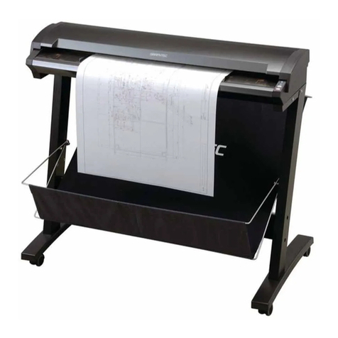
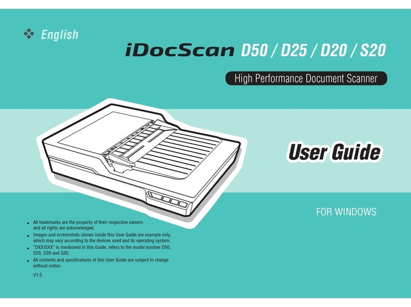
GRAPHTEC SK200-09 User manual

SK200-UM251-03-9370
SERVICE MANUAL
MANUAL NO. SK200-UM-251

SK200-UM-251-9370 i
HISTORY OF REVISIONS
No. Date issued Description of revision Page Edition
1 07.02.06 First Printing. All 01
2 07.04.03
Information for SK200-09-A added.
6-1,8-27 to 32,12-4 02
3 07.04.03
Information for CIS sensor added.
8-16 02
4 07.06.29 Block diagram for SK200-09-A added. 13-2 02
5 07.06.29 Circuit diagrams for SK200-09-A added. 13-28 to 13-52 02
6 08.03.04 Part number for the Left Side Cover Assembly added. 12-1 03
7 08.03.04 Part number for the Right Cover Assembly added. 12-1 03
8 08.03.04 Part number for the Front Guide Assembly added. 12-1 03
9 08.03.04 Part number for the Front Cover Assembly added. 12-1 03
10 08.03.04 Information for the firmware download was added. 9-20 03

SK200-UM-251-9370 ii
CONTENTS
1. OVERVIEW .......................................................................................................................................1-1
1.1 Standard Specifications .......................................................................................................... 1-1
1.2 External View ...............................................................................................................................1-3
2. PART NAMES AND FUNCTIONS ......................................................................................2-1
2.1 Part Names and Functions .....................................................................................................2-1
2.2 Attaching the Rear Guides .....................................................................................................2-3
2.3 Attaching the Anti-curling Guides ......................................................................................2-4
3. CONNECTION AND PREPARATIONS .......................................................................... 3-1
3.1 Connecting to the Power Supply .........................................................................................3-1
3.2 Turning the Power On and Off ..............................................................................................3-2
3.3 System Requirements ............................................................................................................. 3-3
3.4 Connecting the Scanner to a Computer .......................................................................... 3-4
4. INSTALLING THE SOFTWARE .......................................................................................... 4-1
4.1 Installing the Driver Software for Windows XP .............................................................4-1
4.2 Installing the Driver Software for Windows 2000 .........................................................4-3
4.4 Checking the Interface Connection for Windows 2000 ............................................ 4-6
5. DAILY MAINTENANCE ............................................................................................................ 5-1
5.1 Opening and Closing the Top Cover ..................................................................................5-1
5.2 Cleaning the Feed Rollers ......................................................................................................5-2
5.3 Cleaning the Gap Rollers ....................................................................................................... 5-3
5.4 Cleaning the Image Sensors (Contact glass plates) .................................................. 5-4
5.5 Cleaning the Media sensors ................................................................................................. 5-5
5.6 Removing a Jammed Document ......................................................................................... 5-6
5.7 Scanner Calibration ..................................................................................................................5-7
6. RECOMMENDED PARTS LIST .......................................................................................... 6-1
7. LIST OF JIGS AND TOOLS ...................................................................................................7-1
7.1 Jigs ................................................................................................................................................... 7-1
7.2 Tools ................................................................................................................................................ 7-1
7.3 Other ................................................................................................................................................ 7-1
8.
DISASSEMBLING AND ADJUSTING THE MECHANICAL PARTS
.......................................... 8-1
8.1 Top Cover .......................................................................................................................................8-1
8.2 Left Side Cover ...........................................................................................................................8-2
8.3 Right Side Cover ....................................................................................................................... 8-3
8.4 Front Cover .................................................................................................................................. 8-4
8.5 Front Guide Assembly ............................................................................................................ 8-5
8.6 Shield Cover ................................................................................................................................ 8-6
8.7 Control Panel ...............................................................................................................................8-7

SK200-UM-251-9370 iii
8.8 Feed Drive Belt (60S2M250) ................................................................................................. 8-8
8.9 Adjusting Feed Drive Belt Tension (60S2M250) ........................................................... 8-9
8.10 Motor drive belt (60S2M284) ..............................................................................................8-10
8.11 Adjusting the Motor Drive Belt Tension (60S2M284) ............................................... 8-11
8.12 Board Base Chassis .............................................................................................................8-12
8.13 CIS Sensor Unit Assemblies .............................................................................................8-14
8.14 Cover Sensor (LG217L-3) ....................................................................................................8-17
8.15 Media Sensor (PS117ND1) ..................................................................................................8-18
8.16 Top Assembly ..........................................................................................................................8-19
8.17 Feed Rollers .............................................................................................................................8-21
8.18 Adjusting the CIS Sensor Height .....................................................................................8-25
8.19 Contact Glass Plate Assembly .........................................................................................8-26
8.20 Data Controller Board ..........................................................................................................8-27
8.21 CIS (Contact Imaging Sensor) Board ........................................................................... 8-30
8.22 CIS Power Board ....................................................................................................................8-31
8.23 Switching Power Supply Board ...................................................................................... 8-33
8.24 Feed Motor .............................................................................................................................. 8-34
9. ADJUSTMENTS USING THE SOFTWARE ................................................................ 9-1
9.1 Starting the Software ................................................................................................................9-1
9.2 Preparations before Making Adjustments ...................................................................... 9-4
9.3 Preparing a Test Chart ............................................................................................................ 9-5
9.4 Making Adjustments ................................................................................................................ 9-6
Scanner Calibration ..............................................................................................................9-6
1. Calibration (white correction) ......................................................................................9-6
2. Feed distance adjustment .............................................................................................9-8
3. Position adjustment ....................................................................................................... 9-11
4. Color correction (using a color correction sheet) ............................................. 9-18
9.5 Downloading Firmware ..........................................................................................................9-20
1. Items required to download firmware .....................................................................9-20
2. Procedure ...........................................................................................................................9-20
10. TROUBLESHOOTING ..........................................................................................................10-1
11. OPTION AND CONSUMABLES ..................................................................................... 11-1
11.1 Optional Item ............................................................................................................................ 11-1
11.2 Consumables ........................................................................................................................... 11-1
12. PARTS LISTS .............................................................................................................................12-1
12.1 Outer Casing ............................................................................................................................ 12-1
12.2 Front Guide ..............................................................................................................................12-2
12.3 Side Cover ................................................................................................................................12-3
12.4 Main Frame ...............................................................................................................................12-4

SK200-UM-251-9370 iv
12.5 Feed Section ............................................................................................................................12-5
12.6 Bottom Chassis ......................................................................................................................12-6
12.7 Upper Section 1 ...................................................................................................................... 12-7
12.8 Upper Section 2 ......................................................................................................................12-8
12.9 Front CIS Sensor Unit Assembly ....................................................................................12-9
12.10 Rear CIS Sensor Unit Assembly .................................................................................. 12-10
12.11 Inlet .......................................................................................................................................... 12-11
12.12 Other Parts ........................................................................................................................... 12-11
13. BLOCK DIAGRAM AND CIRCUIT DIAGRAMS ...................................................13-1
13.1 Block Diagram .........................................................................................................................13-1
13.1.1 Block Diagram for SK200-09 ............................................................................... 13-1
13.1.2 Block Diagram for SK200-09-A ......................................................................... 13-2
13.2 Circuit Diagrams ................................................................................................................. 13-3
13.2.1 Data Controller Board for SK200-09 ............................................................... 13-3
13.2.2 CIS Controller Board for SK200-09 ............................................................... 13-18
13.2.3 Power Board for SK200-09 ............................................................................... 13-22
13.2.4 Control Panel Board, CN5041-06A ................................................................. 13-26
13.2.5 USB Relay Board, CN5041-07 .......................................................................... 13-27
13.2.6 Data Controller Board for SK200-09-A ........................................................ 13-28
13.2.7 Sub-Data Controller Board for SK200-09-A ...............................................13-44
13.2.8 CIS Controller Board for SK200-09-A ..........................................................13-45
13.2.9 Power Board for SK200-09-A ...........................................................................13-49


SK200-UM-251-9370 1-1
1. OVERVIEW
1. OVERVIEW
1.1 Standard Specifications
Item SK200-09
Document size ANSI E to ISO A4
Maximum width: 965 mm; minimum width: 257 mm*1
Effective scanning area Maximum width : 932.2 mm
Maximum length : 25 m*2
Guaranteed scanning
precision range*3
841 mm x 1189 mm
Document thickness Up to 0.8 mm (including the carrier sheet)
Optical resolution 600 dpi
Interpolated resolution 100, 200, 300, 400, 600, 800, 1200 dpi
Main scanning system Contact image sensor system (Five A4 sensors in a zigzag pattern)
Sub scanning system Document travel (sheet through) system
Scanning speed*4 400 dpi, ISO A0 size
High-speed scan Normal scan High quality scan
• Monochrome: 6 s • Monochrome: 12 s • Monochrome: 12 s
• Grayscale: 6 s • Grayscale: 12 s • Grayscale: 12 s
• 24-bit color: 18 s • 24-bit color: 56 s • 24-bit color: 56 s
Scanning precision*3 ±0.1% ±5 pixels
Gradation Monochrome : Bilevel, intermediate tones (dithering, error diffusion)
Grayscale : 256 shades
Color : 24-bit
Threshold value Digital signal processor enables automatic setting of the threshold value
(monochrome scans only)
Color space sRGB compatible
Sensor
Total number of pixels
22,020 pixels
Output Color: 42 bits/pixel, Grayscale: 14 bits/pixel
Light source LED (RGB)
Interface USB 2.0
Output Image data
Rated power supply 100 to 120/200 to 230 VAC ±10%, 50/60 Hz
Operating environment Temperature: 10˚C to 32˚C
Humidity: 35% to 80% RH (non-condensing)
Power consumption 60 W or less (12 W or less in power-saving mode*5)
External dimensions
(approx.)
1097 (W) x 322 (H) x 160 (D) mm (without stand)
1190 (W) x 405 (H) x 445 (D) mm (including low stand)
1185 (W) x 1100 (H) x 720 (D) mm (including high stand)
Weight (approx.) 24 kg (without stand)
30 kg (including low stand)
38 kg (including high stand)
*1 Load A4-size documents in the Landscape (horizontal) orientation.
*2 If the document is a long-length document, the actual length that can be scanned is limited by the available
memory (hard disk or other data storage device) of the computer to which the scanner is connected, and also by
the grade of the medium being scanned.

SK200-UM-251-9370 1-2
1. OVERVIEW
*3 Notes on scanning precision
The scanning precision may vary slightly depending on the grade and thickness of the medium being scanned,
and on the operating conditions. The precision figures above were measured under the operating conditions
described below.
• Special test chart: Mylar sheet #300
• Guaranteed precision conditions: Temperature: 23°C ±5°C; Humidity: 55% ±15% RH
*4 Including data-transfer time
The following system was used to measure the scanning speeds.
• CPU: Pentium 4, 3.2 GHz or better • Memory: 1 GB or more • Interface: USB 2.0
The scanning speeds may be slower depending on the PC system used.
*5 Only when the power supply is 100 to 120 VAC.

SK200-UM-251-9370 1-3
1. OVERVIEW
1.2 External View
External Dimensions
Unit: mm
Dimensional accuracy: ±5 mm
1070
1097
322
160
When the scanner is mounted on the low stand
1190
405
445

SK200-UM-251-9370 1-4
1. OVERVIEW
When the scanner is mounted on the high stand
1185 720
1100

SK200-UM-251-9370 2-1
2. PART NAMES AND FUNCTIONS
2. PART NAMES AND FUNCTIONS
2.1 Part Names and Functions
Front View/Control Panel
(1) Top cover
Control Panel
(4) Document guides
(3) Top cover open levers
(2) Paper sensors
(6) Power button
(7) POWER LED
(8) PAPER LED
(9) ERROR LED
(10) EJECT key
(11) STOP key
(5) Anti-curling
guides
Top cover
(1) Top cover ..............................Open the top cover to clean the document hold-down unit and contact glass
plates.
(2) Media sensors ......................These sense whether a document is present in the scanner.
(3) Top cover open levers ..........Press these levers to open the top cover.
If the top cover is opened during a scanning operation, the operation will be
stopped compulsorily.
(4) Document guides .................Use these guides to determine the position of a document when you load the
document.
(5) Anti-curling guides ................These guides prevent the document from being caught up in the scanner
during a scanning operation.
Control Panel
(6) Power button ........................Controls the on/off status of the power supply to the scanner.
(7) POWER LED (blue) .............Unlit: The scanner is turned off.
Lit: Lights when the scanner is turned on and remains lit while it is operating
normally.
Flashing: Flashes when the scanner is in power-saving mode.
(8) PAPER LED (green) .............Unlit: Normal status (Local status).
Lit: Lights when a document has been loaded.
Flashing: Flashes while image data is being scanned.
(9) ERROR LED (red) ................Lit: Lights to indicate a hardware error.
Flashing: Flashes when any of the following occurs:
• A document is detected during the self-test when the scanner is turned on
• When a paper jam is detected
• When the top cover is open
• When the document length is shorter than the specified scan length*1
*1 When “Confirm” has been selected for the End-of-paper Processing setting in the driver
software.
Unlit: Normal status

SK200-UM-251-9370 2-2
2. PART NAMES AND FUNCTIONS
(10) EJECT key .........................Press this key to feed the document.
If this key is pressed when the scanner is in document-loaded status, the
document-loaded status is canceled and the document is ejected to the front
of the scanner.
If this key is pressed after the scanning operation has been canceled or
after scanning of the document was halted partway through the scanning
operation, the document-loaded status is canceled and the document is
ejected to the rear of the scanner.
(11) STOP key ...........................Compulsorily stops scanning of the document.
If the ERROR LED flashes when the top cover is in the closed status, press
this key to suspend the scanning operation and check whether a paper jam
has occurred.
Rear View
(13) USB connector
(14) Power inlet
(12) Rear guides
(12) Rear guides ........................The scanned document is aligned with these guides when it is ejected to the
front.
(13) USB connector ...................Used to connect the USB interface cable.
(14) Power inlet .........................Used to connect the power cable.

SK200-UM-251-9370 2-3
2. PART NAMES AND FUNCTIONS
2.2 Attaching the Rear Guides
Always ensure that the rear guides are attached to the scanner unit before scanning a document, irrespective
of the type of document to be scanned.
Caution
The document may be damaged upon contact with the power cable if it is scanned without the rear guides in place.
(1) Insert the ribs on the inside of one of the rear guides into the corresponding slots at the rear of the
scanner, and then push the guide downward.
(2) Repeat the procedure for the second guide.
Checkpoint
Detach the rear guides when moving or packing the scanner. Press lightly against each guide and then lift it up to
detach it.

SK200-UM-251-9370 2-4
2. PART NAMES AND FUNCTIONS
2.3 Attaching the Anti-curling Guides
Always ensure that the anti-curling guides are attached to the scanner unit before scanning a document,
irrespective of the type of document to be scanned.
Caution
A document that has been returned may get caught up in the scanner and become damaged if it is re-scanned with-
out the anti-curling guides in place.
Moreover, depending on the condition of the document, there is a risk of it becoming caught up in the scanner even
when the anti-curling guides are used.
If your document falls into one of the following categories, either place the document inside the carrier sheet that is
available as an option, or have the operator manually guide the returned document so that it does not get caught up
in the scanner.
• Curled documents with a width that exceeds A2-size (420 mm)
• Fragile documents with a width that exceeds A2-size (420 mm)
Be sure to use the carrier sheet for documents in the following conditions:
• Considerably damaged documents
• Badly creased documents
(1) Insert the ribs on one of the anti-curling guides into the corresponding slots into the top cover, and then
slide the guide forward.
(2) Repeat the procedure for the second guide.

SK200-UM-251-9370 3-1
3. CONNECTION AND PREPARATIONSR
3. CONNECTION AND PREPARATIONS
3.1 Connecting to the Power Supply
Connect one end of the power cable provided to the scanner’s power inlet and the other end to an AC power
outlet of the rated supply voltage.
Power cable
Power inlet
AC power outlet

SK200-UM-251-9370 3-2
3. PREPARING TO OPERATE THE SCANNER
3.2 Turning the Power On and Off
The LED (blue) on the [POWER] button changes as follows to indicate the scanner’s power supply status.
• Unlit: The scanner is turned off.
• Lit: Lights when the scanner is turned on and remains lit while it is operating normally.
• Flashing: Flashes when the scanner is in power-saving mode.
Turning the Power On
Press the [POWER] button on the scanner’s control panel.
When the scanner is in the power-on status, the [POWER] button lights blue.
ON
Turning the Power Off
Press the [POWER] button on the scanner’s control panel.
When the scanner is in the power-off status, the [POWER] button LED is extinguished.
OFF
Checkpoint
After the scanner has been turned off, wait at least five seconds before turning it on again.
Notes on the power-saving mode
The scanner automatically switches to power-saving mode (the blue LED on the power button flashes) after
approximately 12 minutes have elapsed without a document being loaded in the scanner. To return the
scanner to normal status (Local status), press either the [STOP] or the [EJECT] key.
To cancel the
power-saving mode

SK200-UM-251-9370 3-3
3. CONNECTION AND PREPARATIONSR
3.3 System Requirements
The minimum system requirements for running the scanner’s hardware and software are listed below.
• Operating system: Windows 2000 Professional, XP Professional, or XP Home Edition
• CPU: Pentium III, 1 GHz
• Memory: 256 MB or more
• Monitor: 1024 x 768 pixels, True Color or higher
• Disk space: At least 10 GB*1
• Mouse
• Interface: USB 2.0 interface
*1 When the document length exceeds length of an A0-size document, additional hard disk space is required.
Recommended environment
• CPU: Pentium 4, 2 GHz
• Memory: 1 GB or more
• Disk space: At least 30 GB
• USB 2.0 interface (that comes standard with your computer)
Checkpoint
Use with a system configuration below the recommended specifications will affect the scanning speed and prevent
the scanner from operating to its specified capabilities. Moreover, colors may not be displayed correctly if the num-
ber of colors that the monitor can display is 256 or less.
To edit an A1-size or larger grayscale document with a resolution of 400 dpi or higher, or a 24-bit color document,
you may need more than the recommended memory sizes above.

SK200-UM-251-9370 3-4
3. PREPARING TO OPERATE THE SCANNER
3.4 Connecting the Scanner to a Computer
USB Connection
A USB cable is used to connect the scanner to the computer, via the respective USB interface connectors.
The connectors at the computer and scanner ends of the USB cable have different shapes. Make sure that
the cable is oriented correctly before making the connection.
Make sure that both the scanner and the computer are in the power-off status when connecting them.
Computer
USB interface connector
USB cable
Important
• Make sure that the USB cable is firmly inserted into the interface connectors.
• The operation of the scanner cannot be guaranteed in the following cases:
t When the cable is connected to a USB hub or an add-on USB board.
t When you are using a custom-built computer or one that you have modified.
• Do not perform any of the following actions:
t Remove or reinsert the cable while you are installing the driver.
t Remove or reinsert the cable while starting up the computer or the scanner.
t Remove or reinsert the cable while transferring data.
t Connect two or more scanners to a single computer.
Checkpoint
Please see the separate “Quick Start Guide” for the scanner driver installation procedure.

SK200-UM-251-9370 4-1
4. INSTALLING THE SOFTWARE
4. INSTALLING THE SOFTWARE
Checkpoint
The procedure outlined below is based on the requirement that you are logged on to Windows with administrator
rights. Consult your Windows 2000 or Windows XP manual for more information.
4.1 Installing the Driver Software for Windows XP
(1) Use the USB cable to connect the scanner to the computer, and then turn on the computer.
(2) When Windows starts up, insert the CD-ROM supplied with the scanner into the CD-ROM drive. The
“Start” screen opens automatically. Click the [Quit] button to close the “Start” screen.
(3) Turn on the power to the scanner.
(4) When Windows XP starts up, the following screen appears (if Service Pack 2 has not been installed, the
screen shown in (5) below appears). Select the option “No, not this time” and then click [Next].
(5) If Service Pack 2 has not been installed, the following screen appears. Select the option “Install from a
list or a specific location (Advanced).” and then click [Next].
(6) The screen shown below is displayed. Select the option “Search for the best driver in these locations”
and select the check box entitled “Include this location in the search.”
Click [Browse] and select the [English]-[DRIVER]-[SCANNER] folders in the CD-ROM drive or enter a
CD-ROM drive name and \English\DRIVER\SCANNER using the keyboard.
Example: For drive D, enter “D:\English\DRIVER\SCANNER”.

SK200-UM-251-9370 4-2
4. INSTALLING THE SOFTWARE
(7) Click [Next]. The wizard will start searching for the driver.
(8) The screen shown below is displayed. Read the explanation and make sure that you understand the
contents.
To continue the installation, click [Continue Anyway].
(9) The screen shown below is displayed when the wizard has finished installing the driver.
Click the [Finish] button to close the “Welcome to the Found New Hardware” wizard.
(10) The Windows XP desktop appears, and the scanner is recognized by the computer.
Other manuals for SK200-09
1
Table of contents
Other GRAPHTEC Scanner manuals

GRAPHTEC
GRAPHTEC CS1000 User manual

GRAPHTEC
GRAPHTEC CS400 User manual
GRAPHTEC
GRAPHTEC CS500 User manual

GRAPHTEC
GRAPHTEC CS500 User manual
GRAPHTEC
GRAPHTEC CS610 User manual

GRAPHTEC
GRAPHTEC CSX500 SERIES User manual

GRAPHTEC
GRAPHTEC CS510 User manual
GRAPHTEC
GRAPHTEC CS600 User manual

GRAPHTEC
GRAPHTEC CS610-11eN User manual

GRAPHTEC
GRAPHTEC CSX500 SERIES User manual
