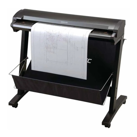
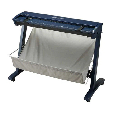
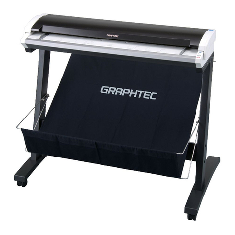
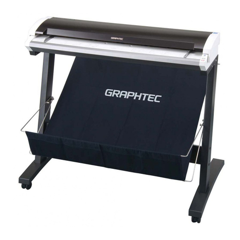
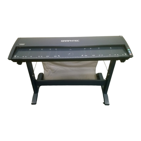
GRAPHTEC CS610 User manual

CS610/CS510/
IS210
USER’S MANUAL
MANUAL NO. CS610-UM-151
IMAGE SCANNER

– i –
TO ENSURE SAFE AND CORRECT USE
•To ensure safe and correct use of your Image Scanner, read this Manual thoroughly
before use.
•After having read this Manual, keep it in a handy location for quick reference as needed.
•Do not permit small children to touch the Image Scanner.
•The following describes important points for safe operation. Please be sure to observe
them strictly.
Conventions Used in This Manual
To promote safe and accurate use of the Image Scanner as well as to prevent human injury
and property damage, safety precautions provided in this manual are ranked into the three
categories described below. Be sure you understand the difference between each of the
categories.
This category provides information that, if ignored, is
highly likely to cause fatal or serious injury to the operator.
This category provides information that, if ignored, is likely
to cause fatal or serious injury to the operator.
This category provides information that, if ignored, could
cause injury to the operator or physical damage to the
Image Scanner.
Description of Safety Symbols
The symbol indicates information that requires careful attention (which includes
warnings). The point requiring attention is described by an illustration or text within
or next to the symbol.
The symbol indicates action that is prohibited. Such prohibited action is
described by an illustration or text within or next to the symbol.
The symbol indicates imperative action (that must be performed). Such im-
perative action is described by an illustration or text within or next to the symbol.
CAUTION
:
DANGER
:
WARNING
:

– ii –
Safety Precautions
WARNING
Do not disassemble, repair, or remodel this scan-
ner.
•Such action may cause a fire hazard or electrical
shock.
•Such action could impair the scanner’s performance
and cause it to malfunction or break down.
If the scanner generates smoke, is abnormally hot,
emits a strange odor, or otherwise functions ab-
normally, do not continue using it. Turn off its
power and unplug its power cord from the elec-
trical socket.
•Use of the scanner in such status may result in a
fire hazard or electrical shock.
•Request repair by contacting your sales representa-
tive or nearest Graphtec vendor.
•Never try to perform repair yourself. Repair work
by inexperienced personnel is extremely danger-
ous.
If the scanner is damaged from being dropped or
other impact, turn off its power and unplug its
power cord from the electrical socket.
•Use of the scanner in such status may result in a
fire hazard or electrical shock.
•Request repair by contacting your sales representa-
tive or nearest Graphtec vendor.
•Never try to perform repair yourself. Repair work
by inexperienced personnel is extremely danger-
ous.
If water or foreign matter enters the scanner, turn
off its power and unplug its power cord from the
electrical socket.
•Use of the scanner in such status may result in a
fire hazard or electrical shock.
•Request repair by contacting your sales representa-
tive or nearest Graphtec vendor.
•Never try to perform repair yourself. Repair work
by inexperienced personnel is extremely danger-
ous.
No disassembly
Unplug the power
cord from the socket
Unplug the power
cord from the socket
Unplug the power
cord from the socket

– iii –
Safety Precautions (Continued)
WARNING
Do not connect the scanner to a non-rated
power supply.
•Use of a different supply voltage may result in a
fire hazard or electrical shock.
CAUTION
Be sure to ground the earth terminal.
•Unless the scanner is grounded, the operator could
suffer an electrical shock in case of current leakage.
Insert the scanner’s power plug securely into
the electrical socket.
•After first connecting the power cord’s female
plug to the scanner, connect its male plug to the
electrical socket.
•Using the scanner with its power plug
incompletely inserted into the electrical socket
could cause a fire hazard or electrical shock.
Do not allow dust or metallic matter to adhere
to the power cord’s plug.
•If the power cord’s plugs become dirty,
thoroughly wipe them clean.
•The use of a dirty power cord plug could result in
a fire hazard or electrical shock.
When the scanner will not be used for an
extended period, unplug its power cord from
the electrical socket.
•Leaving the scanner connected to a power supply
increases its risk of short-circuiting and
overheating.
Ground the
scanner
Prohibited
Beware of electrical shock
Prohibited
Unplug the power
cord from the socket
Securely insert
the power plug
into the socket

– iv –
Safety Precautions (Continued)
CAUTION
Be careful not to damage the power cord or the
interface cable and never use a damaged cord
or cable.
•Do not use unnecessary force to bend, pull, twist,
or bind the cord and cable, place a heavy object
on them, nor remodel them. Such actions could
result in scratches or damage to the cord or cable.
•Use of a damaged power cord or interface cable
may result in electrical shock or a fire hazard.
•Replace the damaged cord or cable with a new one.
When disconnecting the power cord or the inter-
face cable, do not pull on the cord/cable.
•Such action will damage the cord/cable, resulting
in a fire hazard or electrical shock. Be sure to hold
the power cord’s plug or the interface cable’s con-
nector.
Before disconnecting or reconnecting the power
cord, be sure to turn off the scanner.
•Failure to do so may damage the scanner’s per-
formance and cause it to malfunction or break down.
•Failure to do so may result in electrical shock.
Before cleaning the scanner, be sure to unplug
its power cord from the electrical socket.
•Failure to do so may result in electrical shock.
Do not install, use, or store the scanner in a loca-
tion exposed to direct sunlight and/or the direct
draft of an air conditioner or heater.
•Such location may impair the scanner’s performance
due to deformation or other damage and cause the
scanner to malfunction or break down.
Never damage or
use when damaged
Turn off the Power
switch
Pulling prohibited
Unplug the power
cord from the socket
Prohibited

– v –
Safety Precautions (Continued)
CAUTION
Do not install, use, or store the scanner in a
location that does not meet the specified tem-
perature and humidity ranges.
•Such location may impair the scanner’s perform-
ance and cause the scanner to malfunction or
break down.
Do not install, use, or store the scanner in a
location subject to excessive mechanical vibra-
tion or electrical noise.
•Such location may impair the scanner’s perform-
ance and cause the scanner to malfunction or
break down.
Do not install the scanner on an unstable surface.
•The scanner could break due to impact from falling
from the surface or cause injury to the operator.
While the scanner is operating (reading or
ejecting a document), keep hands, clothing, and
other objects away from the document.
•Injury could result from an object getting tangled
in the scanner’s rollers.
Do not place any receptacle containing water or
other fluid on top of the scanner.
•Fluid falling inside the scanner may cause a fire
hazard or electrical shock due to a short circuit
or overheating.
Do not place heavy objects on the scanner.
•Such action may impair the scanner’s performance
due to deformation or other damage, and cause the
scanner to malfunction or break down.
Prohibited
Avoid water areas
Beware of electrical shock
Prohibited
Keep away
Prohibited
Install on a level surface
Prohibited

– vi –
Safety Precautions (Continued)
CAUTION
Do not use sharp, pointed articles on the scanner.
•Such action may impair the scanner’s performance
and cause the scanner to malfunction or break
down.
Do not exert pressure on the scanner.
•Such action may impair the scanner’s performance
and cause the scanner to malfunction or break
down.
•Such action could cause injury to the operator.
Do not attempt to lubricate the scanner’s mecha-
nisms.
•Such action may impair the scanner’s performance
and cause the scanner to malfunction or break
down.
•Such action may cause a fire hazard or electrical
shock due to a short circuit or overheating.
Do not clean the scanner using a volatile solvent
such as thinner or benzine.
•Such action may impair the scanner’s performance
and cause the scanner to malfunction or break
down.
Clean off the scanner’s soiled areas using a soft
cloth that has been moistened with water or a
neutral detergent (diluted with water) and then
firmly wrung out, then wipe the scanner using a
dry cloth.
For more details, see Chapter 5, “Daily Maintenance.”
Prohibited
Prohibited
Prohibited
Prohibited

– vii –
INTRODUCTION
Thank you for purchasing a Graphtec CS610/CS510/IS210 Series Image Scanner. The
CS610/CS510/IS210 Series scanners are capable of performing high-speed scanning of
documents ranging in size from ISO A4 to ANSI E (ISO A4 to ANSI D in the case of the
CS500-06 model).
This User's Manual describes how to operate the CS600/CS500/IS200 Series scanners,
and also includes usage precautions. Read the manual thoroughly prior to use in order to
ensure a full understanding of the product's features, and to ensure effective use. Keep
the manual in a safe place where it can be accessed easily whenever necessary.
Items in this manual marked are precautions to ensure safe use.
Please be sure to observe them strictly.
Notes Regarding This Manual
•All rights reserved. No part of this publication may be reproduced, stored in a
retrieval system, or transmitted, in any form or by any means, without the prior
written permission of Graphtec Corporation.
•The specifications and other information in this manual are subject to change
without notice.
•While every effort has been made to provide complete and accurate information,
please contact your sales representative or nearest Graphtec vendor if you find any
unclear or mistaken information or have other comments or suggestions.
•Notwithstanding the stipulation in the preceding paragraph, Graphtec Corporation
assumes no liability for damages resulting from either the use of the information
contained herein or from use of the product.
•All names of companies, brands, logotypes, and products appearing in this manual
are the trademarks or registered trademarks of their respective companies.
International ENERGY STAR®Program
As an ENERGY STAR®* Partner, Graphtec. has determined that this
product meets the ENERGY STAR®guidelines for energy efficiency.
* The International ENERGY STAR®Office Equipment Program is a global
program that promotes energy saving through the use of computer and
other office equipment. The program backs the development and
dissemination of products with functions that effectively reduce energy consumption. It is
an open system in which businesses can participate voluntarily. The targeted products
are office equipment such as computers, monitors, printers, faxes, copiers. Their
standards and logos are uniform among participating nations.
Trademarks
Windows is a U.S. registered trademark of Microsoft Corp. Other product names
mentioned herein are trademarks or registered trademarks of their respective owners.

– viii –
Scanner Configuration
Note:The stand is an option for the CS510-06 model.
CS610-11eN
CS610-11eN-PRO
CS510-11eN
CS510-11eN-PRO
CS510-06eN-PRO
IS210-11eN
IS210-11eN-PRO
USB/Ethernet model
CS610-11
CS510-11
CS510-06
IS210-11
Scanner name Model number Remarks

– ix –
Usage precautions
Do not lift or move the unit by holding the top cover, as doing so may damage the unit.
Always lift the unit by holding the underside.
Side cover
Top cover Side cover
Take care to prevent your fingers from being caught in the gap between the top cover
and the scanner unit when opening and closing the top cover.
Top cover Top cover
<Opening the top cover>
Do not hold the rear section of
the top cover when opening it.
<Closing the top cover>
Keep your hands away from the front
of the main unit when closing it.
The stand is an option for the CS510-06 model.
Always ensure that you open the top cover and remove the cushion material before using
the product. (Refer to Section 5.1, “Opening and Closing the Top Cover”.)

– x –
Scanner Warm-up
A warm-up period is not usually required for the CS610/CS510/IS210 Series scanners.
However, if you plan to scan a color document (in particular a document with many light
colors), we recommend that you allow the CS610/CS510/IS210 Series scanners to warm
up for 10 minutes before scanning the document.
Precautions to observe when scanning thick documents
When a thick document is scanned, the scanning conditions may need to be changed
depending on the type of document.
(Refer to Section 4.3 “Handling Documents According to their Material and Thickness”.)
Limitations concerning the automatic detection of the document size
Depending on the document’s condition, your scanner may not be able to perform correct
detection of the document size automatically.
(Refer to Page 4-3 “Regarding the automatic detection of the paper size”.)
Scanning at a high resolution
If a scanning resolution of 1200 dpi or higher has been specified, the amount of data will
become extremely large. In such cases, enable the “Use Work File” optional setting in the
Scanning Master 21+ software, and then check that the remaining capacity of your PC’s
hard disk is sufficient before performing the scanning operation.
(Please see the Scanning Master 21+ user’s manual for further details.)

– xi –
Contents
TO ENSURE SAFE AND CORRECT USE
Conventions Used in This Manual............................................................................................. i
Description of Safety Symbols .................................................................................................. i
Introduction...........................................................................................................................vii
1. OVERVIEW
1.1 Features.....................................................................................................................1-1
1.2 Unpacking the Scanner ..............................................................................................1-2
2. PREPARATION
2.1 Assembling the Scanner ............................................................................................2-1
2.2 Part Names and Functions .........................................................................................2-4
2.3 Attaching the Document Support................................................................................ 2-9
3. PREPARINGTO OPERATETHE SCANNER
3.1 System Requirements ................................................................................................ 3-1
3.2 Connecting the Scanner to a Power Supply................................................................3-3
3.3 Connecting the Scanner to a Computer......................................................................3-5
3.4 Connecting the Scanner via an Ethernet Interface ......................................................3-7
3.5 Installing the Driver Software....................................................................................3-18
3.6 Checking the Interface Connection ......................................................................... 3-27
3.7 Installing the Scanning Master 21+ Application......................................................... 3-30
4. LOADING A DOCUMENT
4.1 Compatible Document Types ......................................................................................4-1
4.2 Loading a Document ..................................................................................................4-4
4.3 Handling Documents According to their Material and Thickness .................................4-9
4.4 Distance Correction..................................................................................................4-10
4.5 Using the Carrier Sheet ............................................................................................4-11
5. DAILY MAINTENANCE
5.1 Opening and Closing theTop Cover ........................................................................... 5-1
5.2 Cleaning the Document Hold-Down Unit ....................................................................5-2
5.3 Cleaning the Image Sensors ......................................................................................5-3
5.4 Cleaning the Paper Sensors .......................................................................................5-4
5.5 Removing a Jammed Document ................................................................................ 5-5
5.6 Calibration..................................................................................................................5-7

– xii –
6. TROUBLESHOOTING PROCEDURES
6.1 The scanner is turned on but doesn’t operate at all.....................................................6-1
6.2 The scanner operates improperly after connection to the computer ............................6-1
6.3 The control panel’s red Error LED is lit........................................................................6-2
6.4 The control panel’s red Error lamp is flashing ............................................................. 6-3
6.5 The document isn’t properly fed to the initial scanning position ...................................6-3
6.6 After scanning, image data becomes black or white ...................................................6-3
6.7 The image quality has dropped ..................................................................................6-4
6.8 The input image data is incorrectly aligned ................................................................. 6-4
6.9 Smudges not appearing in the original document appear in the scanned data............ 6-6
6.10 The image-data color intensity differs ......................................................................... 6-6
6.11 The document length differs from the scanned data length .........................................6-6
6.12 Stripes or moiré patterns which are not
in the original document appear in the scanned data .................................................. 6-7
6.13 After scanning, image quality drops............................................................................ 6-7
6.14 After scanning, image data is patchy .......................................................................... 6-7
6.15 The document cannot be fed correctly........................................................................ 6-8
6.16 “Document size cannot be acquired”is displayed ....................................................... 6-8
6.17 The document to be scanned is too short or too long in length ................................... 6-8
6.18 The document stops during the thickness-detection process ...................................... 6-9
APPENDIX A. OPTIONAL AND MISCELLANEOUS ITEMS ...................... A-1
APPENDIX B. STANDARD SPECIFICATIONS ................................................. B-1
APPENDIX C. EXTERNALVIEW............................................................................. C-1
Index ................................................................................................................................... Idex1

CS610/CS510/IS210 1 – 1
1. OVERVIEW
1. OVERVIEW
1.1 Features
600-dpi optical resolution for high-precision image scanning
Scanning with an optical resolution of 600 dpi allows even complex and difficult-to-
scan documents, such as CAD drawings, electronic files, and mapping data to be
scanned rapidly and with high precision. Moreover, the Scanning Master 21+ scanner
software that is included as a standard accessory can be used to adjust the
resolution*1to suit the scanning application.
*1Standard models: 50 dpi to 800 dpi, in 1-dpi increments; PRO models: 50 dpi to
9600 dpi, in 1-dpi increments.
High Quality Scan Mode (PRO models only)
With the PRO models, the scanning quality and scanning speed can be specified to
suit the scanning application. In addition to the 600-dpi high optical resolution, the
“High Quality Scan Mode”, which aims to provide optimum scanning performance, was
incorporated in the PRO models to handle applications where high-quality scanning of
lines and text is required. This mode enables lines to be scanned with a sharp
contrast. Moreover, the interpolated resolution can be specified as a value of up to
9600 dpi, enabling output without any block noise even when large-format copying is
performed.
ITA (Intelligent Thickness Adjustment) Function (CS610 Series models only)
The CS610 Series models are capable of scanning documents with a thickness of up
to a maximum of 20.3 mm. The ITA function performs automatic detection of the
document’s thickness, thereby eliminating complex operations and enabling easy
loading even of thick documents such as A0-size panels.
Choice of two interfaces for easy connection to your PC
The most commonly used high-speed USB 2.0 computer interface is built into all the
CS610/CS510 and IS210 models. In addition, an Ethernet interface is also provided
as standard to enable the use of Ethernet interfaces in a network environment.
Scanning software provided
Graphtec’s proprietary Scanning Master 21+ scanning software is provided as a
standard accessory with each scanner. Moreover, this software can be upgraded to
the Scanning Master Pro Color software with editing functions that is available as an
option.
Compatible document widths range from 210 mm (8 inches) to 1066.8 mm (42 inches)*
2
Documents with a width of up to 1066.8 mm (42 inches)*2can be scanned, as well
as B0-size (1030 mm) documents. Moreover, scanning of long-axis images up to 16
m is supported. With the CS610 models, however, the maximum width that can be
scanned is 762 mm if the document thickness exceeds 1.5 mm.
*2635 mm (25 inches) in the case of the CS510-06 model.

1 – 2 CS610/CS510/IS210
1. OVERVIEW
1.2 Unpacking the Scanner
After unpacking the Image Scanner, check its outer casing and check that the standard
accessories listed below are all present. If you detect a surface flaw or a missing
accessory, please promptly contact your sales representative or nearest Graphtec vendor.
Standard Accessories
Power cable 1
Software CD-ROM 1
Document supports
(CS610-11/CS510-11/IS210-11)
31set
Calibration/Color correction sheets 1 set
•One Calibration sheet
•Calibration sheet for thick documents
(for the CS610 model only)
•One Color correction sheet (CS610/CS510/IS210-PRO only)
User’s Manual 1
Document supports
(CS510-06)
2
Document support wires
Document support plates
Thick document support unit (CS610 only)
Cleaning paper 1 pack
Carrier sheet 1
IS0907 : CS610-11/CS510-11/IS210-11
IS0908 : CS510-06
CS
610/
CS
510/
IS
210
USER'S MANUAL
MANUAL NO.CS610-UM-151
IMAGE SCANNER
Power cable User's Manual Software CD-ROM Document support plates Document support wires Thick document
support unit Carrier sheet Calibration sheets Color correction sheets Cleaning paper

CS610/CS510/IS210 2 – 1
2. PREPARATION
2. PREPARATION
2.1 Assembling the Scanner
The stand is an option for the CS510-06 model.
Two persons are required for the assembly operation.
Assemble the stand before mounting the scanner unit.
(1) Assemble the caster frames and the side stays using the three screws provided.
Side stay
Caster frame
Side stay
Caster frame
(2) Attach the center bar to the side stays temporarily using the four screws provided.
Side stay
Center bar
Groove
Side stay
Caster
Caster
Attach the center bar loosely. Tighten the screws securely after the scanner unit
has been mounted on the stand.

2 – 2 CS610/CS510/IS210
2. PREPARATION
(3) Hold the scanner unit by the underside at both sides as you adjust its position
untilthe rubber feet on the underside of the scanner unit are aligned with the
notches inthe side stays. Place the scanner unit on the stand so that the grooves in
the center bar are facing the front, and then secure it in place using the four coin
screwsprovided.
Holding the scanner by the rear part of the top cover may cause damage to the scanner
or injury to the persons doing the installation. Always hold the scanner by the underside.
Coin screw
Side cover
Rubber feet
Notch
Fixing plate
Coin screw
Fixing plate
Side cover
Groove
Center bar
Fixing plate
(4) Secure the side stays in place by tightening up the four center bar fixing screws
(see (2) above).

CS610/CS510/IS210 2 – 3
2. PREPARATION
(5) Attach the basket to the stand
Position frames 1 and 2 so that they rest on screws A and are hooked onto screws
B in order to attach the basket.
Basket
Screw A
Screw B
Screw A
Screw A
Screw B
Screw A
Frame 1
Frame 2
(6) Attach frame 3 to screws B below screws A and stretch out the basket cloth.
Screw A
Screw A
Frame 3
Screw B
Screw B
(7) Always ensure that you remove the cushion material that is included below the
document hold-down unit before using the product. (Refer to Section 5.1, “Opening
and Closing '†e Top Cover”.)

2 – 4 CS610/CS510/IS210
2. PREPARATION
2.2 Part Names and Functions
Front View
Stand Basket
Top cover
Paper sensor
Cover sensor
Control panel
Caster
Lock
Release
The stand is an option for the CS510-06 model.
Document guides
Release
Top cover
Open the top cover to clean the document hold-down unit and transparent contact plates.
Paper sensors
These sense whether a document is present in the scanner.
Cover sensor
This senses whether the top cover is open or closed, and interrupts scanner operation if
the top cover is opened during operation.
Document guides
Use these guides to determine the position of a document when you load the document.
Control panel
Use the keys to operate the scanner and the LEDs to monitor the operating status.
Stand
The stand unit is assembled for mounting of the scanner unit.
Basket
Receives the document that has been scanned.
Casters
Release the lock on the casters to allow the unit to be moved.
Do not touch the paper sensors.

CS610/CS510/IS210 2 – 5
2. PREPARATION
Rear View
AC line inlet
Power switch
The stand is an option for the CS510-06 model.
Ethernet
connector
USB
connector
Interface
selection switch
Power switch
Controls the on/off status of the power supply to the scanner.
AC line inlet
Connect the power cord’s female plug here.
Interface selection switch
Used to switch between USB and Ethernet (LAN) connection.
This switch is set to USB connection at the time of shipment.
USB connector
Used to connect the USB interface cable.
Ethernet connector*
Used to connect the Ethernet cable.
*: Please do not connect with an Ethernet connector other than an Ethernet cable.
•Make sure that the scanner’s power supply is turned off before using the interface
selection switch to select an interface.
•The USB and Ethernet connectors cannot be used at the same time. Do not
connect both the USB and Ethernet cables to a computer, or to two separate
computers, at the same time.
This manual suits for next models
2
Table of contents
Other GRAPHTEC Scanner manuals

GRAPHTEC
GRAPHTEC SK200-09 User manual

GRAPHTEC
GRAPHTEC SK200-09 User manual

GRAPHTEC
GRAPHTEC CSX300-09 User manual

GRAPHTEC
GRAPHTEC CS400 User manual

GRAPHTEC
GRAPHTEC CS2000 User manual

GRAPHTEC
GRAPHTEC CS610-11eN User manual

GRAPHTEC
GRAPHTEC CS1000EV User manual

GRAPHTEC
GRAPHTEC CS500 User manual

GRAPHTEC
GRAPHTEC CS2000 User manual

GRAPHTEC
GRAPHTEC CS1000 User manual
Popular Scanner manuals by other brands

C Technologies
C Technologies Mobile Information Collector C-Pen user guide

Toshiba
Toshiba Aquilion TSX-101A/I Series Site Planning Manual

Colortrac
Colortrac SmartLF Ci 40 Service manual

Plustek
Plustek OpticPro A320 user guide

X-Rite
X-Rite i1iO quick start guide

Microtec
Microtec Bio-1000F quick start guide