GRAUPNER MC-22S Owner's manual

1
mc
-22s.GB
mc
-22s
3D-Rotary
Programming
System
Programming manual

2
Contents
General notes
Safety notes............................................................... 3
Foreword.................................................................... 6
mc-22s Computer-System......................................... 7
Operating notes ....................................................... 10
Description of transmitter......................................... 18
Using the transmitter for the first time...................... 21
Selecting a channel ................................................. 22
Using the receiver for the first time.......................... 23
Installation notes...................................................... 24
Definition of terms ................................................... 26
3D rotary control functions / screen contrast........... 28
Using the “Data Terminal” ........................................ 29
Assigning external switches and control switches... 30
Digital trims / cut-off trim.......................................... 32
Fixed-wing model aircraft
(receiver socket sequence)...................................... 34
Model helicopters (receiver socket sequence) ........ 36
Programming – a brief introduction
Brief programming instructions................................ 38
Program descriptions
Reserving a new model memory............................. 46
Program descriptions in detail
Page Page
Model memories
Model select 47 47
Copy / erase 47 47
Suppress codes 49 49
Basic settings, transmitter, model and servos
Base setup model 50 50
Model type 52
Helicopter type 53
Servo adjustment 56 56
Contents
Page Page
Transmitter controls
Control adjust 58 60
Control adjust:
throttle limit 62
Dual Rate / Expo 64 66
Channel 1 curve 68 70
Switches
Switch display 72 72
Control switch 72 72
Auxiliary switch 75
Flight phases
Meaning of flight phase program-
ming 76 76
Phase setting
78 79
Phase assignment
80 80
Undelayed channels
81 81
Timers
Timers (general) 82 82
Mixers
Basic mixer functions 84 84
Wing mixers 84
Helicopter mixers 90
Setting up the throttle and coll-
ective pitch curves 96
Helicopter mixer - auto-rotation 99
General notes on freely program-
mable mixers 101 101
Free mixers 102 102
MIX active phase 108 108
MIX-only channel 108 108
Dual mixers 110 110
Swashplate mixer 111
Page Page
Special functions
Fail-safe adjust, PCM 20 112 112
Fail-safe adjust, SPCM 20 114 114
Teacher/pupil 115 115
Global functions
Basic settings 117 117
Servo display 118 118
Code lock 119 119
Programming examples
Fixed-wing models (general) ................................. 120
Non-powered fixed-wing models ........................... 122
Including an electric power system........................ 126
Operating electric motor and butterfly system with
Ch1 stick................................................................ 129
Operating timers using a stick function or switch... 132
Servos operating in parallel................................... 133
Using flight phases ................................................ 134
Controlling timed sequences ................................. 136
Delta / flying wing model aircraft............................ 138
Six-flap wing .......................................................... 142
F3A models ........................................................... 146
Model helicopters .................................................. 150
NAUTIC
Multi-proportional functions ................................... 157
Expert switched functions...................................... 158
Comb. of NAUTIC Multi-Prop a. Expert modules... 159
NAUTIC accessories ............................................. 160
NAUTIC – typical wiring diagram........................... 161
Appendix
Trainer system ....................................................... 162
Transmitter accessories......................................... 163
Approved operating frequencies............................ 168
Approval certificates, conformity............................ 169
Index...................................................................... 170
Guarantee certificate ............................................. 179

3
We all want you to have many hours of pleasure in
our mutual hobby of modelling, and safety is an im-
portant aspect of this. It is absolutely essential that
you read right through these instructions and take ca-
reful note of all our safety recommendations.
If you are a beginner to the world of radio-controlled
model aircraft, boats and cars, we strongly advise
that you seek out an experienced modeller in your
field and ask him for help and advice.
These instructions must be passed to the new owner
if you ever sell the equipment.
Application
This radio control system may only be used for the
purpose for which the manufacturer designed it, i.e.
for operating radio-controlled models which do not
carry humans. No other type of use is approved or
permissible.
Safety notes
SAFETY IS NO ACCIDENT
and …
RADIO-CONTROLLED MODELS ARE NOT
PLAYTHINGS
… because even small models can cause serious
personal injury and damage to property if they are
handled incompetently.
Technical problems in electrical and mechanical sys-
tems can cause motors to rev up or burst into life un-
expectedly, with the result that parts may fly off at gre-
at speed, causing considerable injury.
Please take every possible care to avoid short-circuits
of all types. “Shorts” can easily destroy parts of the
radio control system, but the stored energy in the bat-
tery constitutes an even more serious danger: in un-
favourable circumstances there is a serious risk of fire
and even explosion.
Propellers, helicopter rotors and all other rotating
parts which are driven by a motor or engine represent
a permanent injury hazard. Do not touch these items
with any object or part of your body. Remember that
a propeller spinning at high speed can easily slice off
a finger. Never stand in the primary danger zone, i.e.
in the rotational plane of the propeller or other rota-
ting parts.
When an electric flight or drive battery is connected
to the power system, never touch or even come close
to the propeller or propellers!
When you are programming the transmitter it is im-
portant to avoid the risk of an electric motor or I.C. en-
gine bursting into life unexpectedly. The best course is
to disconnect the fuel supply or the flight / drive batte-
ry before carrying out any work.
Protect all electronic equipment from dust, dirt, damp,
vibration and foreign bodies. Avoid subjecting the
equipment to excessive heat or cold. Radio control
equipment should only be used in “normal” ambient
temperatures, i.e. within the range -15°C to +55°C.
Avoid subjecting the radio control system to shock
and pressure. Check the units at regular intervals for
damage to cases and leads. Do not re-use any item
which is damaged or has become wet, even after you
have dried it out thoroughly.
Use only those components and accessories which
we expressly recommend. Be sure to use only genui-
ne matching GRAUPNER connectors of the same de-
sign with contacts of the same material. Insofar as
they are still required, use only genuine GRAUPNER
plug-in crystals on the appropriate frequency band.
When deploying cables, note that they must not be
under tension, and should never be bent tightly or kin-
ked, otherwise they may fracture. Avoid sharp edges
which could wear through the cable insulation.
Check that all connectors are pushed home firmly be-
fore using the system. When disconnecting compon-
ents, pull on the connectors themselves – not on the
wires.
It is not permissible to carry out any modifications
to the RC system components. Avoid reverse polari-
ty and short-circuits of all kinds involving the connec-
ting leads, as the equipment is not protected against
such errors.
Installing the receiving system and deploying the
receiver aerial
In a model aircraft the receiver must be packed in soft
foam and stowed behind a stout bulkhead, and in a
model boat or car should be protected effectively from
dust and spray.
The receiver must not make contact with the fusela-
ge, hull or chassis at any point, otherwise motor vib-
ration and landing shocks will be transmitted direct-
ly to it.
When installing the receiving system in a model with
a glowplug or petrol engine, be sure to install all the
components in well protected positions so that no ex-
haust gas or oil residues can reach the units and get
inside them. This applies above all to the ON / OFF
switch, which is usually installed in the outer skin of
the model.
Secure the receiver in such a way that the aerial, ser-
vo leads and switch harness are not under any strain.
The receiver aerial is permanently attached to the re-
ceiver. It is about 100 cm long and must not be shor-
tened or extended.The aerial should be routed as far
away as possible from electric motors, servos, metal
pushrods and high-current cables. However, it is best
not to deploy the aerial in an exactly straight line, but
to angle it: e.g. run it straight to the tailplane, then lea-
ve the final 10 - 15 cm trailing loosely, as this helps
to avoid reception “blind spots” when the model is in
the air. If this is not feasible, we recommend that you
lay out part of the aerial wire in an S-shape inside the
model, close to the receiver if possible.
Installing the servos
Always install servos using the vibration-damping
grommets supplied. The rubber grommets provide
some degree of protection from mechanical shocks
and severe vibration.
Safety notes
Safety notes

4
Installing control linkages
The basic rule is that all linkages should be installed
in such a way that the pushrods move accurately,
smoothly and freely. It is particularly important that all
servo output arms can move to their full extent wit-
hout fouling or rubbing on anything, or being obstruc-
ted mechanically at any point in their travel.
It is important that you can stop your motor at any
time. With a glow motor this is achieved by adjus-
ting the throttle so that the barrel closes completely
when you move the throttle stick and trim to their end-
points.
Ensure that no metal parts are able to rub against
each other, e.g. when controls are operated, when
parts rotate, or when motor vibration affects the mo-
del. Metal-to-metal contact causes electrical “noise”
which can interfere with the correct working of the re-
ceiver.
Always extend the transmitter aerial fully before
operating your model
Transmitter field strength is at a minimum in an ima-
ginary line extending straight out from the transmit-
ter aerial. It is therefore fundamentally misguided to
“point” the transmitter aerial at the model with the
idea of obtaining good reception.
When several radio control systems are in use on ad-
jacent channels, the pilots should always stand to-
gether in a loose group. Pilots who insist on standing
away from the group endanger their own models as
well as those of the other pilots.
Pre-flight checking
If there are several modellers at the site, check ca-
refully with all of them that you are the only one on
“your” channel before you switch on your own trans-
mitter. If two modellers switch on transmitters on the
same channel, the result is interference to one or
both models, and the usual result is at least one wre-
cked model.
Before you switch on the receiver, ensure that the
throttle stick is at the stop / idle end-point.
Always switch on the transmitter first, and only
then the receiver.
Always switch off the receiver first, and only then
the transmitter.
If you do not keep to this sequence, i.e. if the receiver
is at any time switched on when its transmitter switch
is set to “OFF”, then the receiver is wide open to sig-
nals from other transmitters and any interference, and
may respond.The model could then carry out uncon-
trolled movements, which could easily result in perso-
nal injury or damage to property. The servos may run
to their end-stops and damage the gearbox, linkage,
control surface etc..
Please take particular care if your model is fitted with
a mechanical gyro:
Before you switch your receiver off, disconnect the
power supply to ensure that the motor cannot run up
to high speed accidentally.
The gyro can generate such a high voltage as it
runs down that the receiver picks up apparently
valid throttle commands, and the motor could re-
spond by accelerating unexpectedly.
Range checking
Before every session check that the system works
properly in every respect, and has adequate range.
This means checking that all the control surfaces re-
spond correctly and in the appropriate direction to the
transmitter commands, at a suitable ground range.
Repeat this check with the motor running, while a fri-
end holds the model securely for you.
Operating your model aircraft, helicopter, boat or
car
Never fly directly over spectators or other pilots, and
take care at all times not to endanger people or ani-
mals. Keep well clear of high-tension overhead ca-
bles. Never run your model boat close to docks and
full-size boats. Model cars should never be run on pu-
blic streets or motorways, footpaths, public squares
etc..
Checking the transmitter and receiver batteries
It is essential to stop using the radio control system
and recharge the batteries well before they are com-
pletely discharged. In the case of the transmitter this
means – at the very latest – when the message “Bat-
tery must be charged” appears on the screen, and
you hear an audible warning signal.
It is vital to check the state of the receiver battery at
regular intervals. When the battery is almost flat you
may notice the servos running more slowly, but it is
by no means safe to keep flying or running your mo-
del until this happens. Always replace worn-out batte-
ries in good time.
Keep to the battery manufacturer’s instructions, and
don’t charge the batteries for longer than stated. Do
not leave batteries on charge unsupervised.
Never attempt to recharge dry cells, as they may ex-
plode.
Rechargeable batteries should always be recharged
before every session. When charging batteries it is
important to avoid short-circuits. Do this by first con-
necting the charge lead banana plugs to the charger,
taking care to maintain correct polarity. Only then con-
nect the charge lead to the transmitter or receiver bat-
tery.
Disconnect all batteries and remove them from your
model if you know you will not be using it in the near
future.
Capacity and operating times
This rule applies to all forms of electrical power sour-
ce: effective capacity diminishes with every charge
cycle. At low temperatures capacity is also greatly re-
duced, i.e. operating times are shorter in cold condi-
tions.
Please note that frequent charging can also result in
a gradual loss of capacity, as can the use of batte-
ry maintenance (cycling) programs. It is important to
monitor your batteries regularly – at least every six
Safety notes
Safety notes

5
months – and check that they still have adequate ca-
pacity for their purpose.
Use only genuine GRAUPNER rechargeable batte-
ries!
Suppressing electric motors
All conventional electric motors produce sparks bet-
ween commutator and brushes, to a greater or lesser
extent depending on the motor type; the sparking ge-
nerates serious interference to the radio control sys-
tem.
In electric-powered models every motor must there-
fore be effectively suppressed. Suppressor filters re-
liably eliminate such interference, and should always
be fitted.
Read the information in the Operating Instructions
and Installation Instructions supplied with your elec-
tric motors for more information on this subject.
Refer to the main GRAUPNER FS catalogue for de-
tails of suppressor filters.
Servo suppressor filters for extension leads
Order No. 1040
Servo suppressor filters are required if you are obli-
ged to use long servo extension leads, as they elimi-
nate the danger of de-tuning the receiver. The filter is
connected directly to the receiver input. In very diffi-
cult cases a second filter can be used, positioned clo-
se to the servo.
Using electronic speed controllers
Electronic speed controllers must be chosen to suit
the size of electric motor which they are required to
control.
There is always a danger of overloading and possib-
ly damaging the speed controller, but you can avo-
id this by ensuring that the controller’s current-hand-
ling capacity is at least half of the motor’s maximum
stall current.
Particular care is called for if you are using a “hot” (i.e.
upgrade) motor, as any low-turn motor (small number
of turns on the winding) can draw many times its no-
minal current when stalled, and the high current will
then wreck the speed controller.
Electrical ignition systems
Ignition systems for internal combustion engines can
also produce interference which has an adverse ef-
fect on the working of the radio control system.
Electrical ignition systems should always be powered
by a separate battery – not the receiver battery.
Be sure to use effectively suppressed spark plugs
and plug caps, and shielded ignition leads.
Keep the receiving system an adequate distance
away from the ignition system.
Static charges
Lightning causes magnetic shock waves which can
interfere with the operation of a radio control transmit-
ter even if the thunderstorm actually occurs several
kilometres away. For this reason ...
... always cease flying operations immediately if
you notice an electrical storm approaching. Static
charges through the transmitter aerial can be life-
threatening!
Caution:
Radio control systems may only be operated on the
frequency bands and spot frequencies approved in
each EU country.You will find information on frequen-
cies in the section “Approved operating frequencies”
on page 168. It is prohibited to operate radio control
systems on any other frequency, and the authorities
are entitled to take appropriate legal action in such
cases.
Care and maintenance
Don’t use cleaning agents, petrol, water or other sol-
vents to clean this equipment. If the case, the whip
aerial etc. gets dirty, wipe them clean with a soft dry
cloth.
Components and accessories
As manufacturers, the company of GRAUPNER
GmbH & Co. KG recommends the exclusive use of
components and accessories which have been tes-
ted by GRAUPNER and approved for their capability,
function and safety. If you observe this rule, GRAUP-
NER accepts responsibility for the product.
GRAUPNER cannot accept liability for non-appro-
ved parts or accessories made by other manufac-
turers. It is not possible for GRAUPNER to assess
every individual item manufactured by other pro-
ducers, so we are unable to state whether such
parts can be used without incurring a safety risk.
Liability exclusion / Compensation
We at GRAUPNER are unable to ensure that you ob-
serve the operating instructions, and are not in a po-
sition to influence the way you install, operate and
maintain the radio control system components. For
this reason we are obliged to refute all liability for
loss, damage or costs which are incurred due to the
incompetent or incorrect use and operation of our
products, or which are connected with such operati-
on in any way.
Unless otherwise prescribed by law, the obligation of
the GRAUPNER company to pay compensation is li-
mited to the invoice value of that quantity of GRAUP-
NER products which was immediately and directly in-
volved in the event in which the damage occurred.
This does not apply if GRAUPNER is found to be sub-
ject to unlimited liability according to binding legal re-
gulation on account of deliberate or gross negligence.
Safety notes

6
The proven mc-22s is now being produced in a new
version under the designation mc-22s, featuring a
PLL Synthesizer RF module as standard. The hard-
ware has also been modified in several respects. For
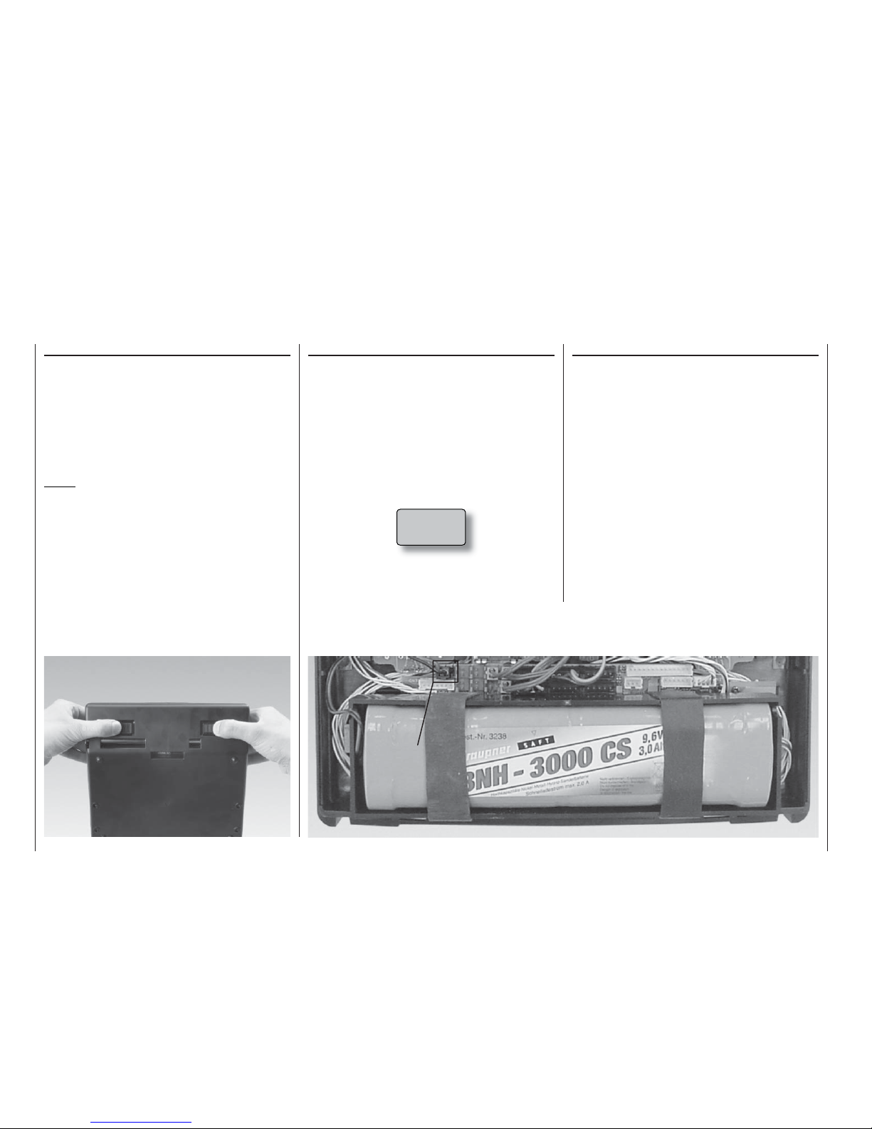
example, “non-volatile memory” is now used to store
model data, eliminating the need for a Lithium back-
up battery if the main battery should be discharged.
The software has also been expanded by the intro-
duction of a language select facility: the entire menu
system can now be switched at any time to German,
English, French or Italian at will, without requiring any
changes to the programming.
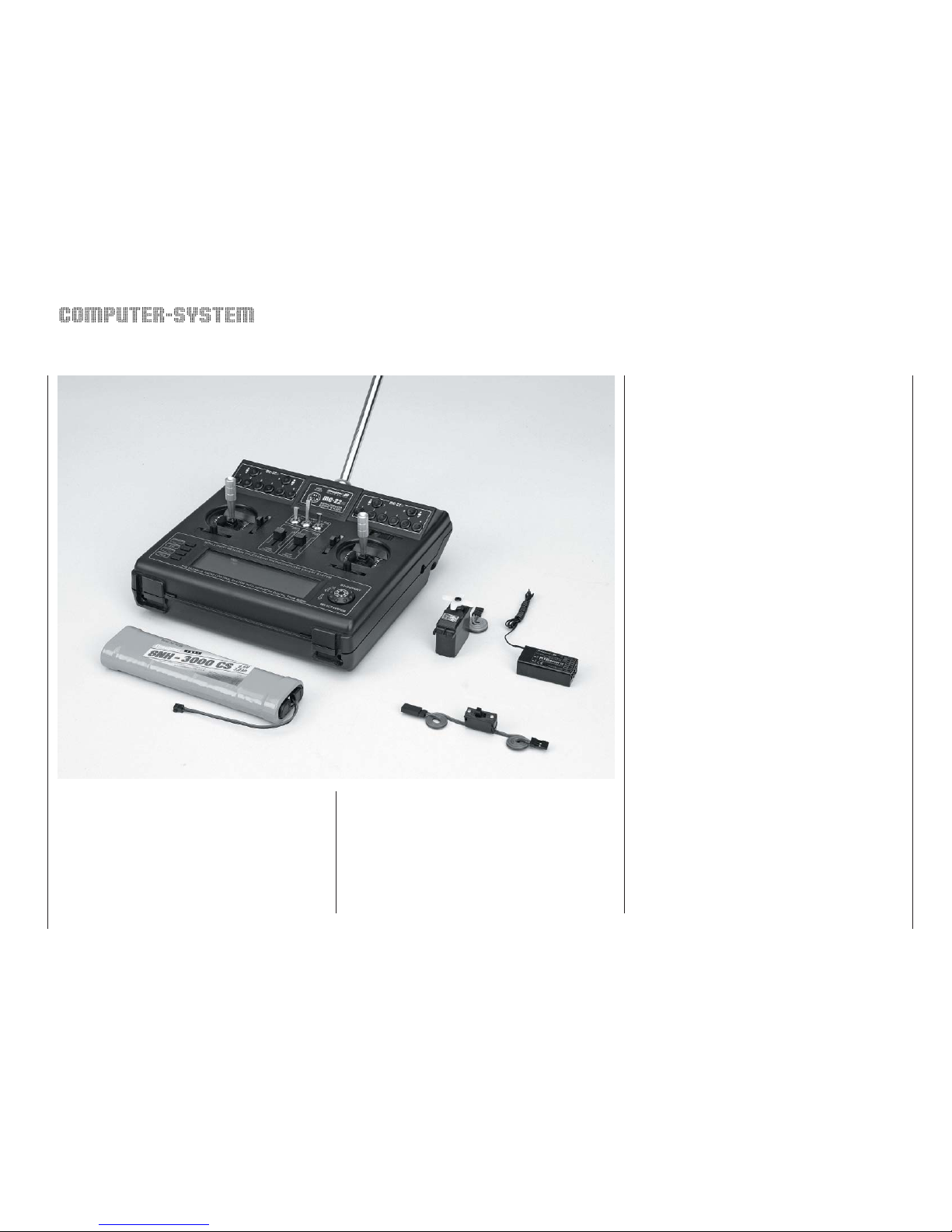
An optional DSC module is now available under Or-
der No. 3290.24. When fitted with this module the mc-
22s transmitter is ideally equipped for use as the con-
trol unit with flight simulators; it can also be connec-
ted directly to a receiver using a DSC lead (see Ap-
pendix). The direct connection is useful for set-up and
testing, as servo signals are transferred to the recei-
ver without the transmission of an RF signal.
The many advantages of the previous mc-22 have
made the system extremely popular, with many thou-
sands of sets already in use, and – as you would ex-
pect – these outstanding features are retained in full
in the new version.
In conjunction with the “DS 24 FM S” mini dual-
conversion receiver, the transmitter can control up
to twelve servos individually. This means that it is
straightforward to use two or more servos on the rud-
der or elevators for the more extreme models.
Fitting the well-known NAUTIC modules provides ad-
ditional expanded functions, which means that fans of
scale model boats and multi-function ships can also
exploit the advantages of the mc-22s.
If used with the new “smc”-series receivers, the mc-
22s can provide servo travel at extremely high reso-
lution with 1024 control increments, ensuring super-
fine control using the SUPER-PCM digital modulation
mode. Naturally we guarantee full compatibility with
earlier PPM / FM receiver systems.
The mc-22s and its software are designed to hand-
le the widely varying requirements of the modern mo-
deller, as well as the more demanding programming
required by the advanced and competition flyer. The
hardware incorporates all the latest developments,
and is laid out in such a way that it can easily exploit
future software development, which continues all the
time.
Operating the transmitter’s software could hardly be
simpler: a digital rotary control and just four “softkeys”
make model programming speedy and direct.
The beginner in particular will certainly appreciate the
carefully designed lay-out of the menus and screen,
conceived with clarity in mind. However, if you en-
counter a problem and the manual is not immediately
to hand, a quick button-press calls up the integral “on-
line help” which will quickly get you back up to speed.
It is important for the beginner’s first attempts at pro-
gramming the transmitter to be as painless as possib-
le, and with this in mind our developers decided to re-
strict the menus available initially to just the basic pro-
gramming essentials. Of course, you can activate all
the facilities of the suppressed menus at any time if
you wish; alternatively you can set the mc-22s trans-
mitter to work in “Expert” (unrestricted) mode from the
outset.
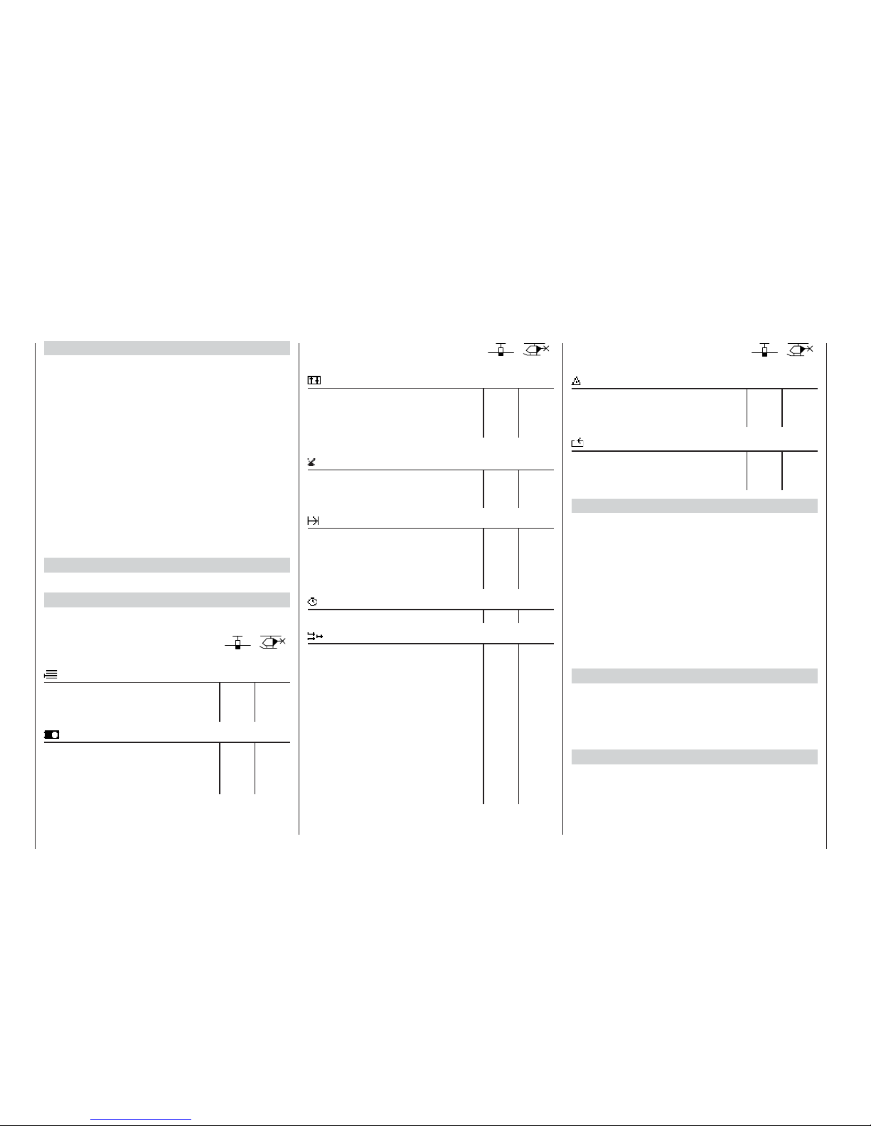
The software is carefully arranged in a neatly structu-
red menu system. Options which are inter-connected
in terms of function are clearly organised by content,
and are symbolised by the following pictograms:
Memory
Basic settings: transmitter, servos, model
Transmitter control settings
Switches
Flight phases
Timers
mc-22s – a new generation of radio control technology
Introduction
Mixers
Special functions
Global functions
The mc-22s provides thirty model memories, each
of which can store model settings for up to four flight
phases. Flight phases can be called up in flight simply
by operating a switch, so that you can try out different
settings quickly and without risk.
The large graphic screen provides a clear display of
all functions, making the transmitter very easy to use.
The settings of the various mixers, Dual-Rate / Expo-
nential and the Channel 1 curve can all be display-
ed in graphic form, and this is extraordinarily helpful
when setting up non-linear curve characteristics.
This manual describes each menu in detail, and also
provides dozens of useful tips, notes and program-
ming examples to complement the basic informati-
on. More general modelling terms, such as transmit-
ter controls, Dual Rates, butterfly and many others,
are all explained in the manual, which also includes a
comprehensive index at the end. You will find a quick-
access tabular summary of the essential operating
procedures on pages 38 to 44.
Please read the Safety Notes and the technical infor-
mation. We recommend that you start by checking all
the functions as described in the instructions. When
you have programmed a model, it is important to
check all the programmed settings on the ground be-
fore committing the model to the air. Always handle
your radio-controlled model with a responsible attitu-
de to avoid endangering yourself and others.
We in the GRAUPNER team offer our grateful thanks
to all the many modellers who have helped us deve-
lop this system by passing on constructive suggesti-
ons, valuable tips and programming examples, and in
so doing have helped us design and produce this ver-
sion of the system and its operating manual.
Kirchheim-Teck, January 2007

7
Description of radio control system
mc
-22s
Expandable radio control system for up to 10 control functions (PPM24: 12 functions)
• World’s first: four-language dialogue menu (Ger-
man, English, French, Italian)
• The latest hardware and integral Synthesizer sys-
tem for channel selection, with security menu to
prevent switching the transmitter on accidentally
• Up to twelve control functions (PPM24)
• Simplified assignment of transmitter controls such
as control sticks, external switches, proportional
controls, trim levers as transmitter controls
• 30 model memories
• 3D rotary encoder in conjunction with four pro-
gramming buttons for accurate adjustment and ex-
cellent programming convenience
• MULTI-DATA high-resolution GRAPHIC LCD
screen provides superb monitoring facilities, ac-
curate graphical representation of multi-point cur-
ves for throttle, collective pitch, tail rotor etc., plus
EXPO / DUAL RATE functions and mixer curves
• CONVENIENT MODE SELECTOR allows easy
switching between stick modes 1 to 4 (e.g. throttle
right / throttle left)
• Real Time Processing (RTP). All selected settings
and changes take immediate effect at the receiver
output, virtually in real time
• ADT Advanced Digital Trim system for all four stick
trim functions, with easily variable throttle / idle
trim and variable trim increment
• Four switchable types of modulation:
PPM 18
The most widely used standard transmission pro-
cess (FM and FMsss).
For C 6, C 8, C 12, C 16, C 17, C 19, DS 18, DS
19, DS 20 receivers, and XP 4, XP 8, XP 10, XP
12, XN 12, XM 16, R16SCAN, R 600 light, R 600,
R 700, C 6 FM, SB6 SYN 40 S, SR6SYN miniatu-
re receivers
Professional high-technology micro-computer ra-
dio control system. Ultra-speed low-power single-
chip micro-computer with 256 kByte (2 Mbit) flash
memory, with 16 kByte (128 kbit) RAM, 73 ns com-
mand cycle!
With integral high-speed precision A/D converter
and proven, highly practical dual-function rotary
encoder and 3D rotary select programming tech-
nology.

8Description of radio control system
PPM24
PPM multi-servo transmission mode for simultane-
ous operation of up to twelve servos. For the DS
24 FM S receiver
PCM 20
PCM with system resolution of 512 steps per con-
trol function. For mc-12, mc-20, DS 20 mc recei-
vers.
SPCM 20
Super PCM modulation with high system resoluti-
on of 1024 steps per control function.
For smc-14 S, smc-16 SCAN, smc-19, SMC-19
DS, smc-20, smc-20 DS, smc-20 DSYN, smc-20
DSCAN receivers
• Six freely programmable mixers for fixed-wing mo-
dels and helicopters, of which two in each case
are five-point curve mixers, freely variable in 1%
increments. An ingenious polynomial approximati-
on process is applied, generating an ideally roun-
ded curve based on your selected mixer reference
points.
• The five-point throttle and collective pitch cur-
ves available in the helicopter menu also feature a
multi-point curve system (MPC). An ingenious po-
lynomial approximation process is applied, gene-
rating an ideally rounded curve based on your se-
lected mixer reference points.
• Two-stage Expo / Dual Rate system, individually
variable, switchable in flight, separately variable for
each model
• Helicopter swashplate mixers for 1, 2, 3 and 4-
point linkages
• Integral flight phase menus, sub-trim for neutral
point adjustment of all servos, aileron differential
mixer, butterfly (crow) mixer, flaperon mixer
• Graphical servo display provides a fast, straightfor-
ward overview for checking servo settings
• Servo travel limiting for all servo channels, variab-
le separately for each end-point (single-side servo
throw)
• Programmable fail-safe function with variable time
hold or pre-set function (PCM and SPCM only)
• Stop-watch / count-down timers with alarm func-
tion
• Operating hours timer, available separately for
each model
• HELP button provides valuable hints on program-
ming and the currently selected programming
menu
• Model copy function for all model memories
• Prepared for an interface module for copying bet-
ween two mc-22s transmitters, mc-22 / mc-22s, or
between mc-22s and PC
• Two NAUTIC modules and decoders can be con-
nected for function expansion: each NAUTIC mo-
dule expands one receiver output to form eight
switched channels or four proportional functions.
• Prepared for use as Pupil or Teacher transmitter in
a Trainer system
• Non-volatile memory for data back-up even with
transmitter battery removed or completely dischar-
ged
mc
-22s
Expandable radio control system for up to 10 control functions (PPM24: 12 functions)

9
Description of radio control system
mc-22s
Micro-computer Radio Control System
Radio control sets:
Order No. 4737 35 / 35B MHz band
Order No. 4738 40 / 41* MHz band
Transmitters alone:
Order No. 4737.77 35 / 35B MHz band
Order No. 4738.77 40 / 41* MHz band
* 41 MHz approved for use in France only
Set contents:
mc-22s micro-computer transmitter with factory-fitted
NiMH transmitter battery, can be expanded from six
to max. ten proportional control functions.
Synthesizer RF module on the appropriate frequency.
R16SCAN PLL Synthesizer FM receiver on the same
frequency (max. eight servo functions), C 577 servo,
Switch harness,
4.8 V NC receiver batteries: see main GRAUPNER
FS catalogue.
Specification - mc-22s computer system
Transmission system SPCM 20, PCM 20, PPM 18, PPM 24 -
switchable
Radio Frequency
section
Integral (10 kHz spacing), 35, 35B, 40 or
41 MHz band
Spot frequencies 35 MHz band: chan. 61 - 80, 281*, 282*
35 MHz B-band: channels 182 - 191
40 MHz band: 50 - 59 and 81 - 92
41 MHz band: 400 - 420*
Channel spacing 10 kHz
Max. control func-
tions
SPCM = 10, PCM = 10, PPM = 12
Control functions,
basic version
4 functions, with digital trims plus
2 proportional functions
Optional extra chan-
nel functions
4 proportional or switched
Channel pulse width 1,5 ms ± 0,5 ms
Control resolution SPCM 20: 10 Bit (1024 Steps),
PCM 20: 9 Bit (512 Steps)
Aerial Telescopic aerial, ten sections, approx.
1470 mm long
Operating voltage 9,6 ... 12 V
Current drain approx. 55 mA (excl. active RF module)
Dimensions approx. 225 x 215 x 70 mm
Weight approx. 980 g incl. transmitter battery
* To recharge the mc-22s system you will also need the transmit-
ter charge lead, Order No. 3022, and the receiver battery char-
ge lead, Order No. 3021.
** 12 V power source required.
Please refer to the main GRAUPNER FS catalogue
for details of other chargers.
Recommended battery chargers (optional)
Order No. 6422 Minilader 2
Order No. 6427 Multilader 3
Order No. 6426 Multilader 6E*
Order No. 6428 Turbomat 6 Plus*
Order No. 6429 Turbomat 7 Plus*
Automatic battery chargers with special NiMH charge
programs:
Order No. 6419 Ultramat 5*, **
Order No. 6410 Ultramat 10*,
Order No. 6412 Ultramat 12*, **
Order No. 6414 Ultramat 14*,
Order No. 6417 Ultramat 25*, **
Order No. 6416 Ultra Duo Plus 30*, **
Specification - R16SCAN receiver
Type PLL-SCAN narrow-band
FM SUPERHET synthesizer receiver
35 / 35B MHz band
40 / 41 MHz band
Order No. 7052
Order No. 7054
Spot frequencies:
35 MHz
40/41 MHz
61 …282*/182 …191
50 … 92 /400 … 420*
Operating voltage 4,8 ... 6 V **
Current drain approx. 24 mA
Channel spacing 10 kHz
Sensitivity approx. 10 µV
Modulation PPM 18
Servo sockets 8 Stück***
Temperature range
approx. -15° ... +55 °C
Aerial length approx. 1000 mm
Dimensions approx. 46 x 25 x 15 mm
Weight approx. 17 g
* Channels 281, 282 and channels on the 41 MHz frequency
band are not approved for use in Germany. See page 168 for
frequency table.
** 4 NC / NiMH cells or 4 dry cells
*** Servo 8 is connected to the socket marked “8 / Batt.” using a Y-
lead Order No. 3936.11 or 3936.32, in parallel with the receiver
battery.
Replacement part
Order No. 4300.6 Telescopic transmitter aerial
Stainless steel telescopic aerial
Order No. 4300.60
10-section telescopic aerial, ultra-robust construction.
Can be used instead of the standard telescopic aerial.
Please refer to the Appendix and the main GRAUP-
NER FS catalogue for details of additional accesso-
ries for the mc-22s radio control set.

10 Operating notes
Opening the transmitter case
Before opening the transmitter, please check that it is
switched off (move Power switch to “OFF”). Slide both
latches inwards as far as they will go, in the opposi-
te direction to the arrows, until the case back can be
folded open and disengaged.To close the transmitter,
engage the bottom edge of the case back, fold the
panel up again and slide both latches outwards in the
direction of the arrows.Take care that no wires get
caught when you close the back.
Notes:
•Do not modify the transmitter circuit in any
way, as this invalidates your guarantee and also
invalidates official approval for the system.
•Never touch the circuit boards with any metallic
object. Don’t touch any electrical contacts with
your fingers.
•Whenever you wish to work on the transmitter,
start by disconnecting the transmitter battery
from the transmitter circuit board to avoid the
possibility of short-circuits (see column at far
right).
Power supply
The battery compartment is fitted as standard with a
high-capacity 9.6 V NiMH battery (8NH-3000 CS, Or-
der No. 3238 – specification may change). However,
this battery is not charged when the transmitter is de-
livered.
When you are using the transmitter you can monitor
the battery voltage on the LCD screen. If the voltage
of the transmitter battery falls below a certain point,
you will hear an audible warning signal. The screen
then displays a message reminding you that the
transmitter battery needs to be recharged:
Charging the transmitter battery
The rechargeable transmitter battery can be charged
via the charge socket fitted to the side of the case.
The transmitter must be switched off and left at
“OFF” for the whole period of the charge process.
Never switch on the transmitter when it is still
connected to the charger; even a very brief inter-
ruption in the charge process can cause the char-
ge voltage to rise to the point where the transmit-
ter is immediately damaged by the excess vol-
tage. Alternatively the interruption may trigger a
new charge cycle, which means that the battery
will inevitably be totally overcharged.
For this reason check carefully that all connectors are
secure and are making really good contact. Interrup-
tions due to an intermittent contact, no matter how
brief, will inevitably cause the charger to malfunction.
Operating notes
Socket for transmitter battery
Batt must
be re-
charged!!

11
Polarity of the mc-22s charge socket
Commercially available battery charge leads pro-
duced by other manufacturers are often made up
with reversed polarity. For this reason use genuine
GRAUPNER charge leads exclusively.
Charging the transmitter battery using a standard
charger
The integral transmitter charge socket is fitted with a
safety circuit which prevents reverse current flow.This
is designed to prevent damage to the transmitter if
the charge lead is connected with reverse polarity, or
if the bare ends of the lead short out.
This protective measure makes it impossible to re-
charge the transmitter battery using an automatic
charger, as the charger is unable to check and moni-
tor the battery voltage properly. Automatic chargers
usually respond to this by terminating the charge pro-
cess prematurely, throwing up error messages or re-
fusing completely to charge the pack.
The basic rule for charging a flat battery with a stan-
dard charger (without automatic cut-off) is: charge
for fourteen hours at a current corresponding to one
tenth of the capacity printed on the pack. This is 300
mA for the transmitter battery fitted as standard. It is
up to the user to terminate the charge at the correct
time …
Charging the transmitter battery with an auto-
matic charger
By-passing the reverse flow safety circuit
If you wish to use an automatic charger to recharge
the transmitter battery, the reverse flow safety circuit
(protective diode) mentioned in the previous column
must be by-passed.This is done by fitting a 20 mm
cartridge fuse (5 Amp, fast-acting) in the fuse holder.
If you by-pass the reverse flow safety circuit, the-
re is a constant danger of short-circuit between
the charge lead plugs. If a short-circuit or reverse
polarity occurs, the transmitter’s charge circuit fuse
will immediately blow.
A blown fuse must always be replaced by a new
20 mm glass cartridge fuse (5A, fast-acting). Never
attempt to repair the fuse by by-passing it. Replace-
ment fuses are available in any electronics supply
shop.
Maximum charge current
To avoid damage to the transmitter the maximum
charge current should not exceed 500 mA (0.5 A)
with the charge circuit fuse out of circuit (not fitted);
with the charge circuit fuse in place: max. 1.5 A.
Removing the transmitter battery
To remove the transmitter battery,
carefully disconnect the plug from
the transmitter circuit board, pulling
the connector upwards by the cable.
Locate the rubber bands at the bat-
tery compartment and push them
to the side slightly. The battery can
then be slid out of the compartment
sideways.
Check the state of the batteries at regular intervals.
Don’t wait to recharge the batteries until you notice
the servos working more slowly than usual.
On-screen battery operating hours display
#01 0:00h C73
H-J Sandbrunner
11.3V
0:00h
0 0 0 0
St watch
Flighttm
0 00
0 00
:
:
This timer shows the cumulative operating time of the
transmitter battery since the last time the battery was
recharged.
This timer is automatically reset to the value “0:00” as
soon as the transmitter circuit detects that the voltage
of the transmitter battery is significantly higher than
last time, i.e. the pack has been recharged in the me-
antime.
Transmitter charge
plug polarity
brown or
black
red
Operating notes
Fuse, 5A, fast-acting

12 Operating notes
Operating notes
Charging the receiver battery
A wide variety of rechargeable 4.8 V NC and NiMH
batteries is available, varying in capacity. For safety
reasons always use ready-made battery packs from
the GRAUPNER range; never use dry cells.
There is no direct method of checking receiver batte-
ry voltage when operating a model.
For this reason it is important to make it a stan-
dard part of your routine to check the state of
your batteries at regular intervals. Don’t wait until
you notice the servos running more slowly than
usual before recharging the packs.
The charge lead, Order No. 3021, can be connec-
ted directly to the NC receiver battery for charging.
If the battery is installed in a model and you have in-
stalled one of the following switch harnesses: Order
No. 3046, 3934, 3934.1 or 3934.3, the battery can be
charged via the separate charge socket, or the char-
ge socket which is built into the switch. The switch on
the switch harness must be left at the “OFF” position
for charging.
Standard chargers
Order No. 6422 Minilader 2
Order No. 6427 Multilader 3
Order No. 6426 Multilader 6E*
Order No. 6428 Turbomat 6 Plus*
Order No. 6429 Turbomat 7 Plus*
Automatic chargers with special NiMH charge
programs
Order No. 6419 Ultramat 5*, **
Order No. 6410 Ultramat 10*, **
Order No. 6412 Ultramat 12*, **
Order No. 6414 Ultramat 14*, **
Order No. 6417 Ultramat 25*, **
Order No. 6416 Ultra Duo Plus 30*, **
* To recharge the mc-22s system you will also need the transmit-
ter charge lead, Order No. 3022, and the receiver battery char-
ge lead, Order No. 3021.
** 12 V power source required.
Please refer to the main GRAUPNER FS catalogue
for an overview of batteries, battery chargers and
measuring equipment.
General notes on battery charging
• Keep to the recommendations provided by the ma-
nufacturers of the charger and the battery at all ti-
mes.
Observe the maximum permissible charge current
stated by the battery manufacturer. To avoid dama-
ge to the transmitter circuitry, the maximum char-
ge current for the transmitter battery is 1.5 A; limit
the charge current to this value on the charger.
If you wish to charge the transmitter battery at a
current higher than 1.5 A, it is absolutely essen-
tial to remove the pack from the transmitter for
charging. If you ignore this, you risk damaging the
transmitter circuit board by overloading the tracks
and / or overheating the battery.
• If you are using an automatic battery charger, car-
ry out a series of test charges to ensure that the
automatic charge termination circuit works correct-
ly with your battery.
This applies in particular if you are recharging the
standard NiMH battery using an automatic charger
designed for NiCd batteries.
You may need to adjust the Delta Peak trigger vol-
tage, if your charger provides this option.
• Do not discharge the battery or carry out a battery
maintenance program via the integral charge so-
cket. The charge socket is not suitable for this ap-
plication.
• Always connect the charge lead to the charger
first, and only then to the transmitter or receiver
battery. Observing this rule eliminates the danger
of accidental short-circuits between the bare con-
tacts of the charge lead plugs.
• Never leave batteries on charge unsupervised.
Polarity of recei-
ver battery

13
Operating notes
Adjusting stick length
Both sticks are infinitely variable in length over a
broad range, enabling you to set them to suit your
personal preference to provide fine, accurate control.
Loosen the retaining screw using a 2 mm allen key,
then screw the stick top in or out to shorten or extend
it. Tighten the grubscrew again carefully to lock the
set length.
Changing the stick mode
Either or both sticks can be converted from self-neu-
tralising to non self-neutralising (ratchet) action: open
the transmitter as already described.
If you wish to change the standard setting, use this
procedure:
1. Disconnect the centring spring from the appropria-
te neutralising arm using a pair of tweezers. If you
are not sure, move the stick to check. Raise the
neutralisation return arm and disconnect it.
2. Fix the ratchet spring (supplied)
to the plastic pillar using the black
self-tapping screw, then screw the
M3 screw in or out to set the desi-
red spring force on the side of the
hexagon sleeve.
3. Check that the stick functions
work correctly, then close the
transmitter case again.
Brass
pillar
Changing back to “self-neutralising” action
Open the transmitter as already described.
1. Remove the ratchet spring, as shown in the illust-
ration on the left.
2. Now re-connect the neutralising lever on the side
of the stick unit where the ratchet spring was loca-
ted.
3. First loosen the stick force adjustment screw
slightly – see the illustration on the next page –
and then draw a length of thin thread through the
top loop in the spring, but without tying it. Connect
the spring to the bottom loop of the adjustment
system using a pair of tweezers, then pull the top
end of the spring up using the thread, and connect
it to the neutralising lever. Once the spring is posi-
tioned correctly, withdraw the thread again.
4. Adjust the stick centring spring force as described
in the next section.
Neutralising lever

14 Operating notes
Stick centring force
The tension of the stick unit centring springs can be
adjusted to suit your personal preference: the ad-
justment system is located adjacent to the centring
spring. Rotate the adjustor screw with a cross-point
screwdriver to set your preferred spring force:
• Turn to the right (clockwise) = spring force harder;
• Turn to the left (anti-clockwise) = spring force sof-
ter.
Operating notes
Changing frequency bands and channels
The mc-22s transmitter is equipped as standard with
a PLL Synthesizer RF module.The channel you wish
to use is selected using the rotary control; plug-in
crystals are not required for the transmitter.
A detailed description of the procedure for using the
Synthesizer module and setting the appropriate chan-
nel is found in the section entitled “Using the transmit-
ter for the first time – selecting channels” on page 22.
The set channel is displayed on the screen. A security
system prevents an RF signal being generated when
the transmitter is switched on. The RF module must
first be activated in the software, which provides an
additional margin of safety.
Two sets / two transmitters are available for the 35 /
35B MHz band and the 40 / 41 MHz band:
Radio control sets:
Order No. 4737 35 / 35B MHz band
Order No. 4738 40 / 41* MHz band
Transmitters alone:
Order No. 4737.77 35 / 35B MHz band
Order No. 4738.77 40 / 41* MHz band
* Channels 281 and 282 in the 35 MHz band, and all channels in
the 41 MHz band, are not approved for use in Germany. Please
refer to the frequency table on page 168, The table also lists the
channels which may legally be used for the various model ty-
pes, i.e. model aircraft, model boats and model cars.
Please refer to the frequency table on page 168 for
a list of the channels which are valid in the European
continent at time of going to press.
The receiver must be operated on the same channel
and on the same frequency band as the transmitter.
You can use any GRAUPNER PLL Synthesizer re-
ceiver with the transmitter, together with all earlier
crystal-controlled GRAUPNER receivers, provided
that they are compatible with the transmission mo-
des PCM20, SPCM, PPM18 and PPM24 (see pages
7 and 8 and the main GRAUPNER FS catalogue for
more information on this subject).
If you wish to use earlier crystal-controlled GRAUP-
NER receivers, it is essential to use genuine GRAUP-
NER FMsss plug-in crystals exclusively (see page
168). The receiver crystal is marked “R” (Receiver),
and should be pushed firmly into the socket in the re-
ceiver.
Important note:
The RF-Synthesizer module is connected to the
transmitter circuit board by means of two cables. If the
cables are not plugged in correctly, or if the 4-pin plug
is withdrawn in order to install a Pupil module (see
page 163), the transmitter switches directly to the
basic display when switched on. Instead of a channel
number, the screen now displays the flashing symbol
“C––” ; in order to indicate that the RF module is not
ready for use:
-ODELNAME
H#
(*3ANDBRUNNER
6
H
3TWATCH
&LIGHTTM
Changing frequency bands:
For reasons of safety a switch of RF module from the
35 / 35B MHz to the 40 / 41 MHz band (or vice ver-
sa) can only be carried out by a GRAUPNER Service
centre.

15
Operating notes
Re-positioning the telescopic aerial
Screw the ten-section telescopic aerial into the ball-
and-socket base. The angle of inclination of the aerial
can be adjusted mechanically as follows: loosen the
cross-point screw to the side of the socket, swivel the
aerial to your preferred angle, then carefully tighten
the screw again.
Notes:
• When you switch on the transmitter, do not activa-
te the RF module without the aerial screwed into its
socket. The telescopic aerial should always be ex-
tended to its full length for controlling a model “in
earnest”, and even for protracted testing.
• The field strength radiated by the transmitter is at
its lowest in an imaginary line extending straight
out from the tip of the transmitter aerial. Never
point your aerial straight at the model in an attempt
to obtain good reception; the opposite is true.
Installing the transmitter support bars
The transmitter can be fitted with the optional trans-
mitter support system, Order No. 1127. This is the
procedure: open the transmitter and remove the case
back, which is prepared to accept the support system
bars. Locate the four holes in the case back which
are designed to accept the support bars, and push a
cross-point screwdriver through them from the rear to
clear the openings, twisting it gently to act as a drill.
Installing NAUTIC modules, external switches,
switch modules and rotary modules
The transmitter case is supplied with all the holes for
the installation of optional modules already present.
Start by disconnecting the transmitter battery to avo-
id short-circuits.
The holes are sealed by blind grommets which can
easily be pushed out from the inside.
Using a suitable blunt instrument, press out the mo-
dule covers on the front face of the transmitter from
the inside by pushing through the existing holes.
Place the new bezel in position, and check that it fits
correctly. Remove the backing paper from the adhe-
sive surface of the bezel, position it carefully, then
press it down firmly. Peel the protective film from the
printed front surface of the bezel.The module can
now be fitted in the prepared module well from the in-
side, ensuring that the row of sockets on the module
faces the centre of the transmitter.
The support bars are held in place under strong tensi-
on by a long spring. If you find the spring tension un-
comfortably high, shorten the spring accordingly.
Slide the plastic retai-
ner bracket for the metal
bars between the lugs in
the back panel, and fit two
screws from the underside
into each bracket.
Now push the metal bars
of the support system
through the holes in the
back panel, working from
the inside.

16 Operating notes
Operating notes
Secure the module using the nuts and rotary knobs
which you previously removed from the potentiome-
ters and switches. Screw the nuts onto the shafts on
the outside of the transmitter and tighten them care-
fully using a suitable box spanner.
Socket assignment on the transmitter circuit
board
You will find on a sketch of the transmitter circuit
board on page 19.
Additional transmitter controls can be connected to
function sockets CH5 ... CH10 on the transmitter cir-
cuit board; these include rotary controls, sliders and
switch modules (see Appendix).
Note:
Two additional inputs can be assigned to controls
such as external switches by software, so that up to
twelve separate control functions are available at the
transmitter when using the DS 24 FM S receiver.
In its standard form the transmitter features two 2-
channel sliders installed in the centre console; the-
se controls are connected to sockets CH6 and CH7
as standard. If you wish, you can reverse the direction
of operation of the transmitter control “mechanical-
ly” by turning the connector through 180° at the trans-
mitter circuit board. However, a more elegant method
is to use the »Control adjust« menu, where you can
reverse and adjust the transmitter controls using the
system software.
The external switch sockets can be assigned in any
arrangement you wish, as you define the external
switch for software assignment simply by operating it,
which means that the number of the socket is irrele-
vant.
However, in the interests of clarity and comprehensi-
bility we do recommend that you assign the sockets
in numerical order, and install the corresponding swit-
ches in the proper sequence – from 0 to max. 7 – in
the transmitter case, insofar as that is possible.
The NAUTIC module (Order No. 4141 or 4108) or the
Teacher module (Order No. 3290.2 or 3289) can be
connected directly to the 14-pin connector using the
mc-22(s) / mc-24 adaptor (Order No. 4184.1). If you
install the mc-22(s) interface distributor, Order No.
4182.3, you can connect both modules to the trans-
mitter in parallel. A full description of the individu-
al modules is included at the appropriate point in this
manual.
The last step is to fit the rotary knobs on the potenti-
ometer shafts, line them up with the graduated scale,
and tighten the grubscrews.
External switches, rotary modules and switch modu-
les are installed in a similar way.
Take great care not to touch the solder pads on the
transmitter circuit board with any metallic object.
We recommend the use of the special box
spanner, Order No. 5733, for tightening the
decorative nuts which retain the external swit-
ches.
External switch
sockets 0 ... 7
Function sockets
CH5 ... CH10

17
Operating notes
The original function of this socket was for “Direct
Servo Control”, and that’s why the abbreviation is still
in use. However, it is now much more versatile than
simply providing a means of controlling servos by ca-
ble. The DSC socket can now be used as an alterna-
tive to the Teacher socket (see pages 115 and 162),
also as an interface for flight simulators.
For the DSC connection to work you must check
the following:
1. Carry out any adjustments required in the approp-
riate menus:
If you are connecting the transmitter to a flight si-
mulator (for example), these settings are found in
the »Modulation« line of the »Base setup mo-
del« menu – “PPM” is usually required.
If you are connecting a Diagnosis lead (Order No.
4178.1), the modulation must be selected to suit
the receiver – see below.
2. Always leave the transmitter’s On / Off switch in
the “OFF” position, for only at this setting is the RF
section of the transmitter module switched off (no
RF signal) even when the DSC lead is plugged in.
This is particularly important if you are using a Di-
agnosis lead, otherwise you could still cause inter-
ference to other pilots.
3. Connect the appropriate connecting lead to the
optional DSC socket on the back of the transmit-
ter. This renders the transmitter ready for use, cir-
cumventing the channel select process, and the
LCD screen operates. At the same time the let-
ters “DSC” appear on the LCD screen, instead of
the usual display of the transmission channel you
have selected.
4. Connect the other end of the connecting lead to
the desired piece of equipment, after referring to
the operating instructions supplied with it. If you
wish to use the Diagnosis lead, Order No. 4178.1,
do not connect it directly to the receiver. First con-
DSC socket
Direct Servo Control
Environmental
protection notes
nect the lead to a receiver battery using a Y-lead
(Order No. 3936.11 or 3936.32), and connect this
to the receiver’s battery input socket instead of the
receiver battery. The end with the barrel plug can
then be connected to the appropriate socket on
the back of the transmitter. Once the transmitter
is connected to the receiver as described above,
you can check the control functions or make chan-
ges to settings even if another pilot is using “your”
frequency. Since (power = “OFF”) the transmit-
ter does not broadcast a radio signal in this state,
you can, for example, prepare your model ready
to fly without causing interference to other pilots.
Another advantage is that the transmitter’s current
drain is reduced to only about 70 mA, since the
transmitter’s RF section is not active in this mode
of operation. Diagnosis mode operations therefore
extend the operating time of the transmitter battery
considerably.
Important:
Ensure that all the cables are firmly plugged in.
Note regarding flight simulators:
The range of flight simulators available commercially
is now very wide, and you may find that it is necessa-
ry to swap over certain contacts at the battery plug or
the DSC module. Do not attempt this work yourself; it
must be carried out by a GRAUPNER Service Centre.
Caution:
Certain receivers – such as the R16SCAN – feature
a battery socket to which a servo can also be con-
nected via a Y-lead. In this case it is not possible
to use a DSC lead.
Notes regarding environmental protection
Do not discard exhausted dry or rechargeable batte-
ries in the ordinary domestic refuse. As end-user you
are legally required (by the “Battery Regulation”) to
return old and exhausted dry cells and rechargeab-
le accumulators. For example, you can take them to
your local community recycling centre, or to any retail
outlet where batteries of the same type are sold.
The presence of this symbol on a pro-
duct, in the user instructions or the pa-
ckaging, means that you must not dispo-
se of that item, or the electronic compo-
nents contained within it, in the ordinary
domestic waste when the product comes
to the end of its useful life. The correct method of dis-
posal is to take it to your local collection point for re-
cycling electrical and electronic equipment. Dry cells
and rechargeable batteries must be removed from the
device and taken separately to a suitable battery dis-
posal centre.
Individual markings indicate which materials can be
recycled and re-used.You can make an important
contribution to the protection of our shared environ-
ment by re-using the product, recycling the basic ma-
terials or re-processing redundant equipment in other
ways.
If you don’t know the location of your nearest disposal
centre, please enquire at your local council office.

18 Description of transmitter
Ball / socket aerial base
Storage well on back panel
Option well for PC interface, Order No. 4182
Option wells
Locations for external switches, switch modules,
rotary modules, NAUTIC modules; see Appendix.
Switches and function modules
• 3 external switches as standard
• 2 sliders as standard
Digital trims
For fine adjustment of servo (neutral) position. A
brief push produces a single increment of offset
(increment size variable in »Base setup model«
menu). The screen shows the trim position.
Operating buttons:
ENTER Input button
ESC Return button
CLEAR Erase button
HELP Help button
LCD screen
See page 20 for a full description.
Contrast adjustment: press rotary control and rotate simultaneously.
Warning signals:
• If battery voltage falls below set threshold
• If Trainer system malfunctions
• If Channel 1 stick is at full-throttle when transmitter is switched on
• If Fail-Safe settings are not correct
ON / OFF switch
Note:
Always switch the transmitter on first, then the
receiver. After a flight: switch the receiver off
first, then the transmitter.
Stick units
Two dual-axis stick units providing four independent
control functions. Variable-length sticks. The prima-
ry control functions (i.e. stick mode) can be assigned
within the »Base setup model« menu, e.g. throttle
left or right. The throttle stick can also be set to self-
neutralising or ratchet action; see page 13.
Rotary control, provides two-level control
(normal and pressed-in)
Switches between individual lines within a menu when
held pressed-in.
Changes the input field, or confirms your input, when
pressed briefly.
A brief press on the rotary control at the basic display
switches to »Servo display«.
If rotated in its normal (non-pressed) state, the rota-
ry control selects the desired Code from the list in the
multi-function menu. If you call up a menu point, the
rotary control also changes the entered value in an in-
verse-video field which appears at the bottom edge of
the screen in (light characters on dark background).
Set values take effect immediately, and are also stored
immediately.
Description of transmitter

19
Description of transmitter
Note:
Whenever you intend to work on the interior
of the transmitter, remember to disconnect the
transmitter battery from the power socket.
Take great care not to touch soldered joints with
any metallic object, as this could cause a short-
circuit.
It does not matter which way round you connect the
external switches.
Reversing the orientation of the control connector
simply reverses its direction of effect.
Synthesizer RF module:
The channel is selected in the software when you
switch the transmitter; see page 22.
For safety reasons the RF module can only be swit-
ched from the 35 / 35B MHz to the 40 / 41 MHz band
(or vice versa) by an authorised GRAUPNER Service
centre.
RF module
socket
(4-pin)
Socket for
connection
to RF Syn-
thesizer
module
Service socket (for
use by GRAUPNER
Service Centres only)
Sockets 0 ... 7 for
external switches
(see Appendix)
DSC module*
socket
* DSC = Direct Servo Control.
see page 17 and Appendix
Battery socket
Battery plug
polarity
Transmitter fuse,
0.5A, fast-acting
Function sockets CH5 ...
CH10 for transmitter con-
trols (rotary knobs, switch
module, slider module;
see Appendix)
Interface distributor socket
Transmitter circuit board
0
2
4
6
71
35 CH5 CH7 CH9
CH6 CH8 CH10
Charge socket
Battery charge circuit fuse
(5A, fast-acting) for use
with automatic chargers;
see page 11.
Jumper for service use:
do not touch!
Polarity of charge socket

20 Description of LCD screen
ENTER (Input button):
Switch to multi-function list, call
up a menu
ESC (Escape button)
Return step by step from any
menu to the basic display
CLEAR (Erase button)
Resets altered values to default
settings
HELP (Help button)
Provides a brief help message re-
lating to any menu
Model name
Model memory
1 ... 30
User’s name
(max. 15 characters)
Number of the selected
transmission channel
Model operating time
Superimposed warning messages*:
Notes:
* If the transmitter battery voltage is too low, the message “Not currently pos-
sible; battery voltage too low” appears in the »Model Select« and »Copy /
Erase« menus.
** For safety reasons this warning can only be disabled by selecting an unpowe-
red fixed-wing model: this is done by selecting “none” in the “Motor” line of the
»Model Type« menu; see page 52.
Stopwatch in minutes
(count-up / count-down)
Flight time in minutes
(count-up / count-down)
Battery voltage with dynamic bar display.
If voltage falls below the pre-set level a
warning message appears and a buzzer
sounds.
Transmit-
ter operating
time. This va-
lue is auto-
matically re-
set to zero
when the bat-
tery is re-
charged.
Model type
display:
fixed-wing
aircraft or
helicopter
Display diagram for
all four digital trim
levers with nume-
ric and directional
display: „“ or „“.
Special cut-off trim
for Ch. 1 (see page
32).
Dual-level rotary control
Adjusts screen contrast in
basic transmitter display
with control pressed in.
GRAUPNER logo; alternatively flight phase name,
Flight phases are selected using a physical switch
Description of LCD screen
Fail Safe
setup
Thr
too
high!
None
student-
signal
Trainer mode
problem
Throttle stick at
full-throttle**
Charge battery Only in PCM20
and SPCM20
mode
Batt must
be re-
charged!!
Table of contents
Popular Control System manuals by other brands

Exhausto
Exhausto VEX150CF H Original instructions

Roberts Gorden
Roberts Gorden System Control HP 120 V 1 Installation & operation

Stahl
Stahl TRANBERG 4900 Installation and user manual

Medem
Medem SEC-Le V4 installation instructions

Pilz
Pilz PSS u2 ES 16DOD 0.5A operating manual

Distech Controls
Distech Controls ECLYPSE APEX user guide

BriskHeat
BriskHeat XtremeFLEX MSTAT Series instruction manual

TCS
TCS CS-105 quick start guide

Endress+Hauser
Endress+Hauser Smart System for Surface Water SSP100B operating instructions

Siemens
Siemens SINUMERIK 808D Programming and operating manual

NEC
NEC NEAX2000 IVS user manual

ADVANTAGE AIR
ADVANTAGE AIR MyAir5 Series user guide